

Introduction
Today we spotlight FSP’s high-performance 2000W SiC server power supply (Model: FSP2000-20FM). Engineered for robust data center applications, it supports universal 100–127V and 200–240V AC inputs alongside 240V DC input compatibility. It delivers a massive 12V main output at 163.6A, accompanied by a 12V 3A auxiliary standby rail, all backed by 80 PLUS Platinum certified efficiency.
Built to the standard CRPS185 form factor, it employs an advanced PFC + phase-shifted full-bridge + SR topology, leveraging premium onsemi SiC MOSFETs and Infineon SiC diodes. Let's dive straight into the teardown to inspect FSP's industrial-grade engineering and component selection.
Product Appearance
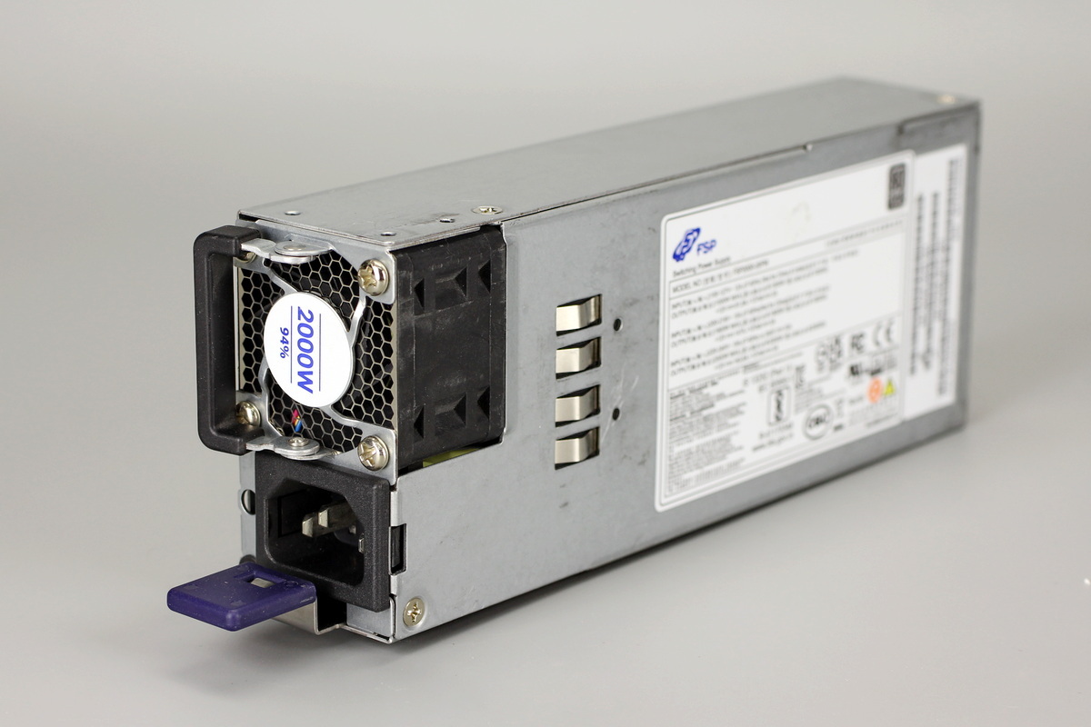
The FSP 2000W server PSU adopts a galvanized steel housing, with an info label pasted on the front.
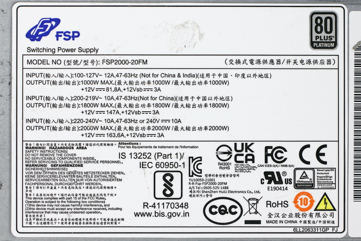
The power supply info label:
Model: FSP2000-20FM
AC Input: 100–127V~, 47–63Hz
DC Output: 1000W Max
+12V ⎓ 81.8A, +12Vsb ⎓ 3A
AC Input: 200–219V~, 47–63Hz
DC Output: 1800W Max
+12V ⎓ 147A, +12Vsb ⎓ 3A
AC Input: 220–240V~, 50/60Hz, 10A
DC Input: 240V ⎓ 10A
DC Output: 2000W Max
+12V ⎓ 163.6A, +12Vsb ⎓ 3A
FSP Group Inc. Made in China
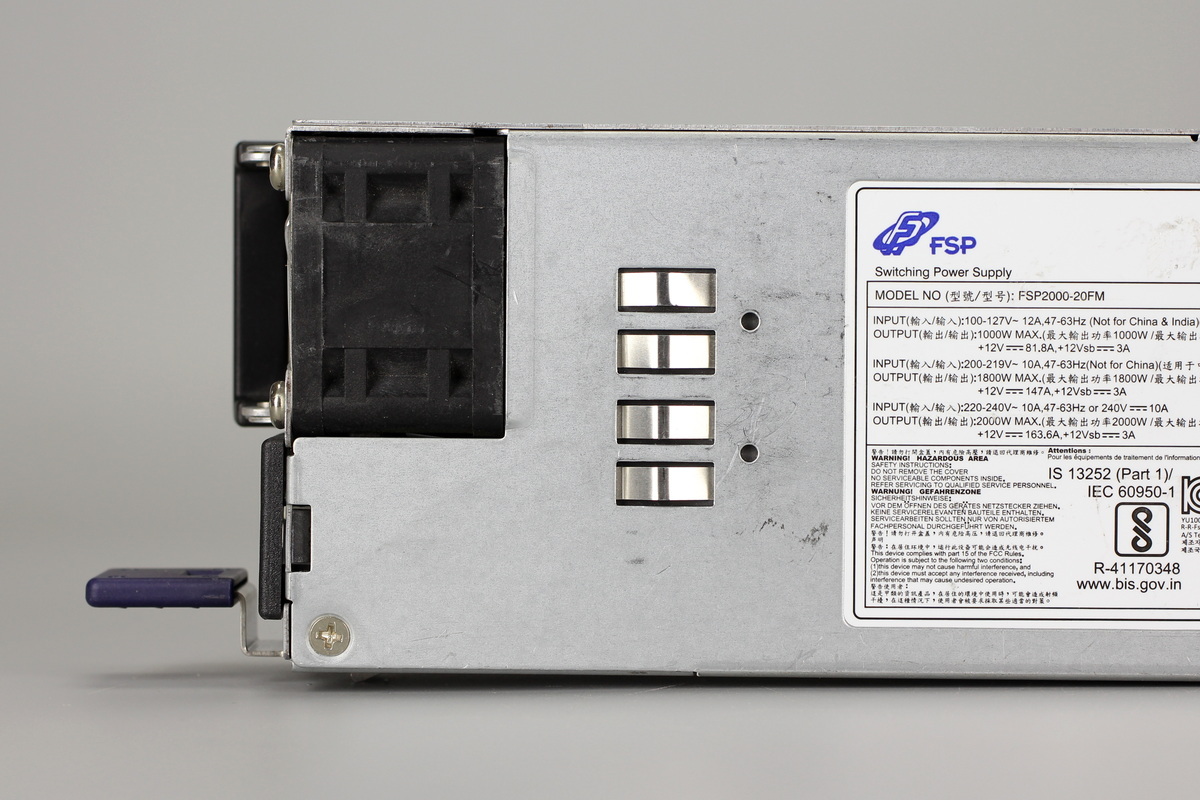
A cooling fan is installed at the input end, while a grounding spring contact is located on the front.
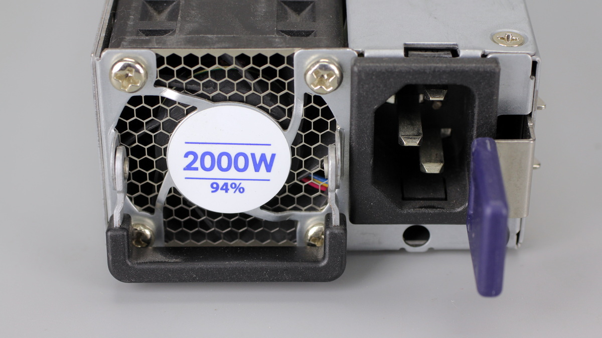
The input end features a cooling fan, an IEC power inlet, an installation handle, and an LED indicator.
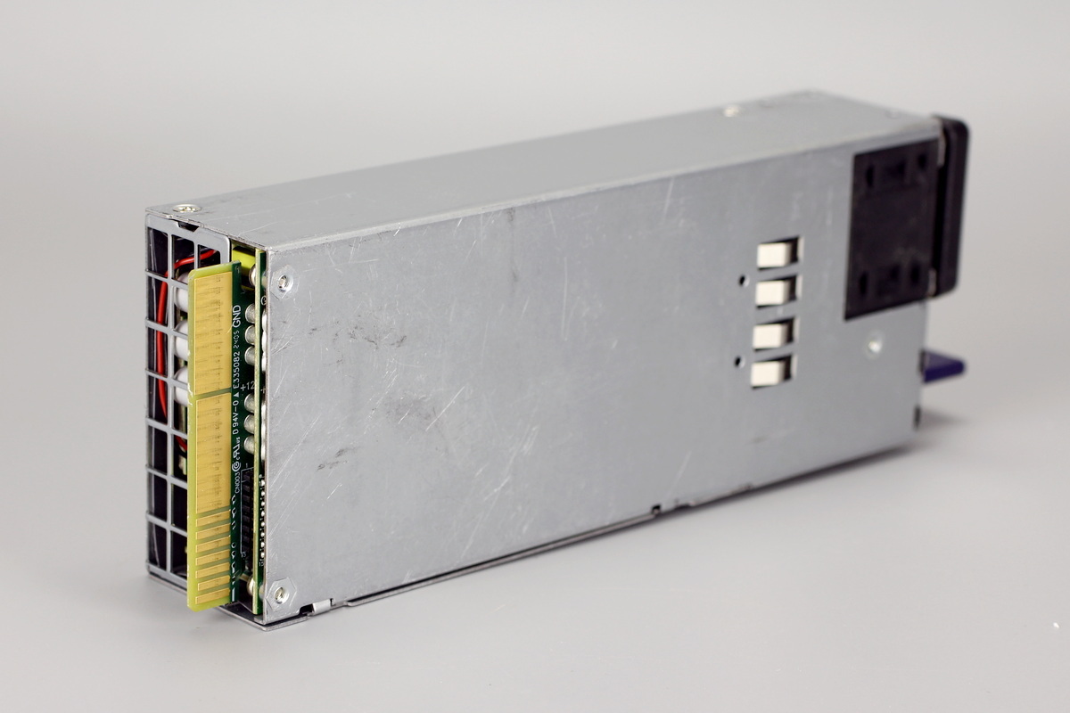
A grounding spring contact is located on the back of the housing.
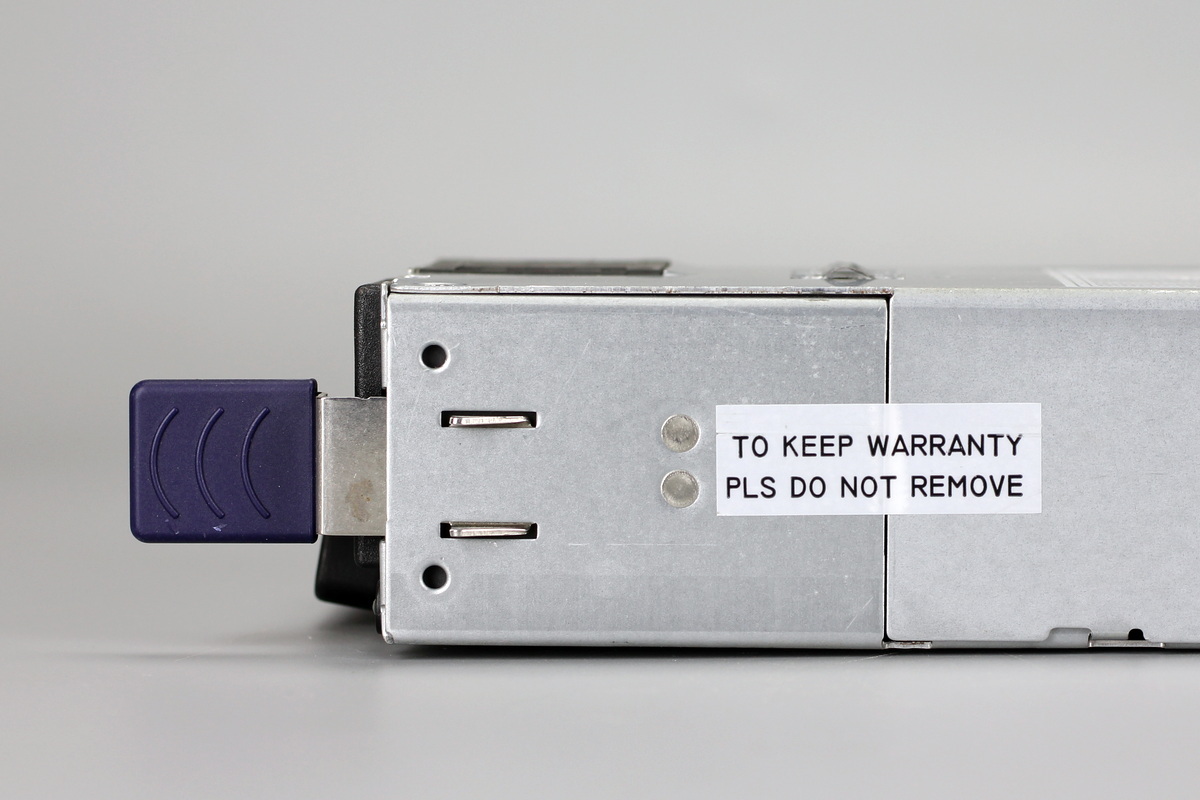
The locking latch fixed to the side.
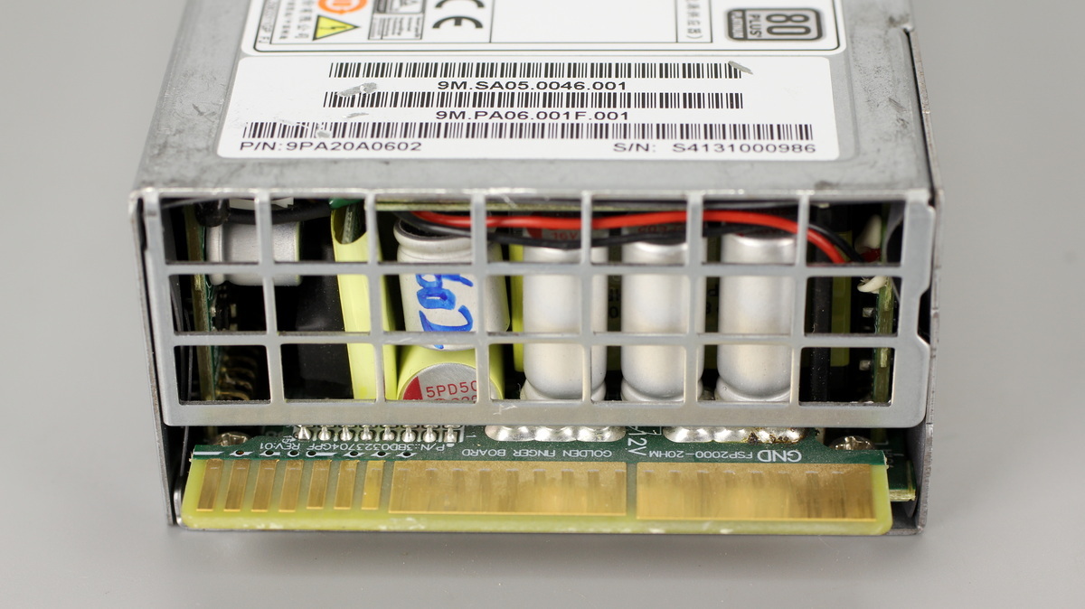
The output end features a ventilation grille and PCB edge contacts.
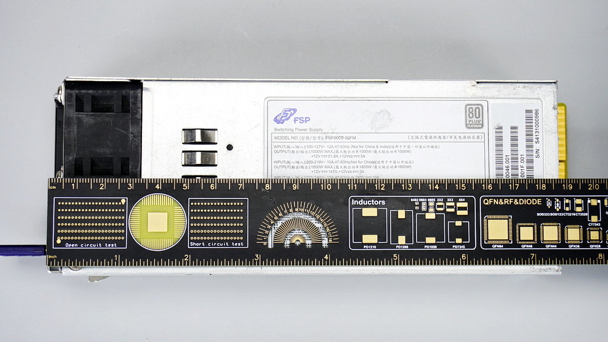
The length of the power supply is about 185mm (7.283 inches).
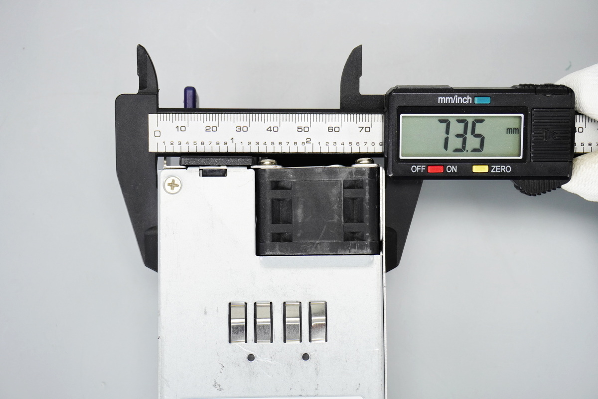
The width of the power supply is about 73.5mm (2.894 inches).
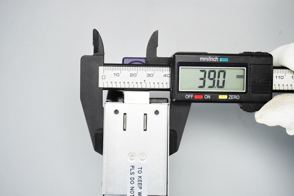
The thickness of the power supply is about 39mm (1.535 inches).
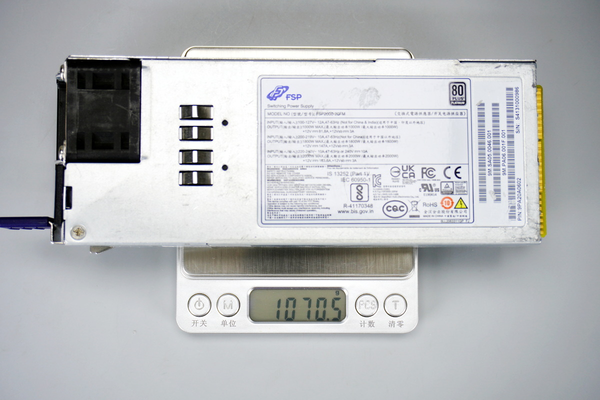
The weight is about 1070g (37.743 oz).
Teardown
With the exterior overview complete, we dive into the teardown of the FSP 2000W server PSU to see how it is built inside.
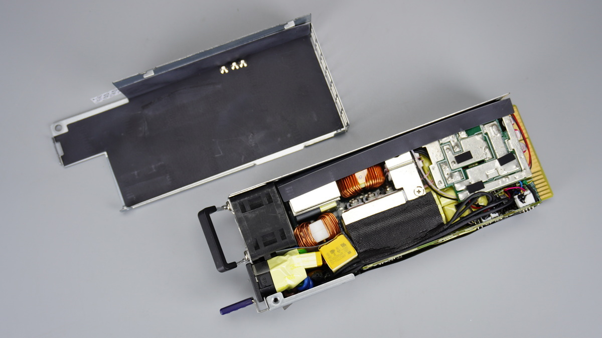
Removing the fixing screws and opening the housing reveals that a PCBA module is wrapped with a Mylar sheet for insulation.
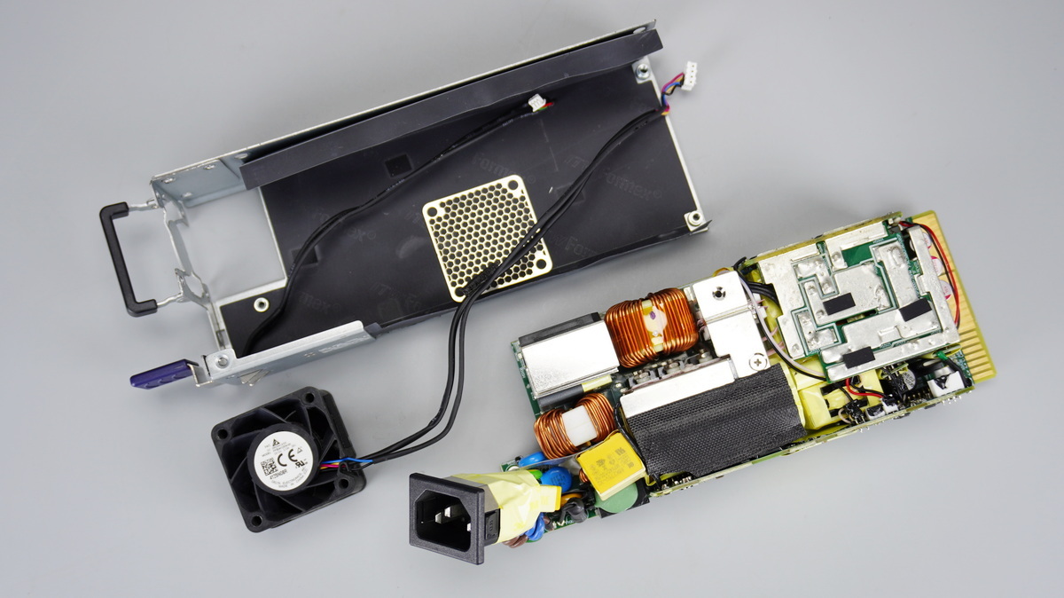
Remove the fixing screws and take out the PCBA module, and a Mylar sheet is also installed inside the housing for insulation.
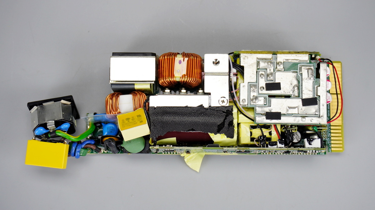
The front of the PCBA module shows that left side is the AC input end, equipped with a fuse, varistor, common-mode choke, safety X2 cap, relay, and thermistor, with a heat sink for the bridge rectifier located above. The PFC boost inductor is positioned on the right, while the heat sink below is used for the PFC switching MOSFETs and PFC rectifier MOSFETs.
High-voltage filter caps are located below, while the heat sink for the phase-shifted full-bridge switching MOSFETs is positioned at the upper right. To the right of the heat sink is the transformer, with a synchronous rectifier PCB above it. The filter inductor and filter caps are located on the right. Below are the standby power transformer, filter caps, and control PCB.
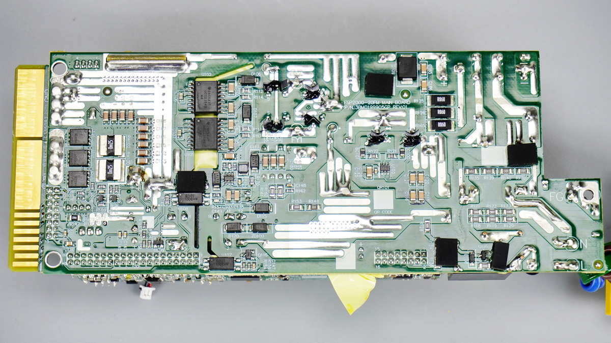
The back features current-sense resistors, isolated drivers, optocouplers, and output control MOSFETs.
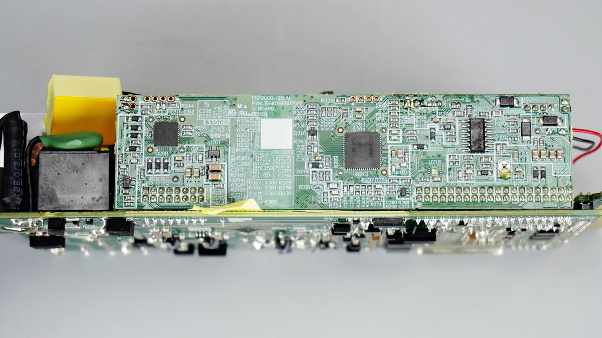
The side features a relay, thermistor, and control PCB.
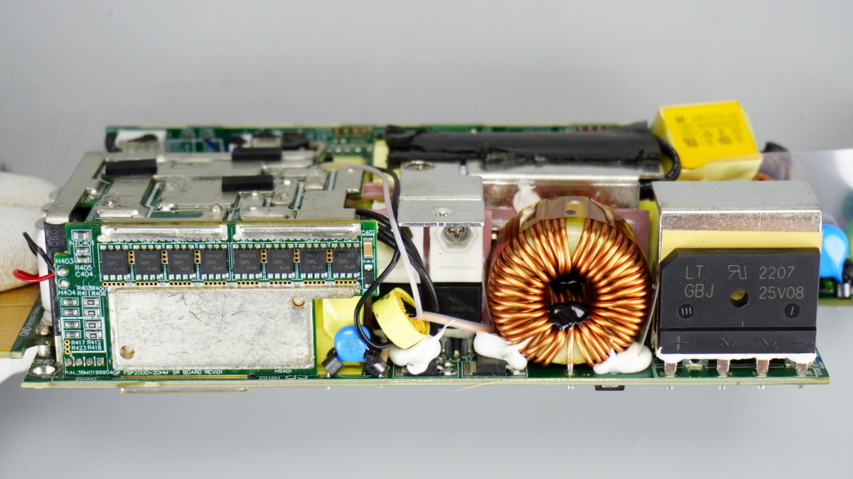
The other side features the bridge rectifier, PFC boost inductor, phase-shifted full-bridge switching MOSFETs, current transformer, and synchronous rectifier PCB.
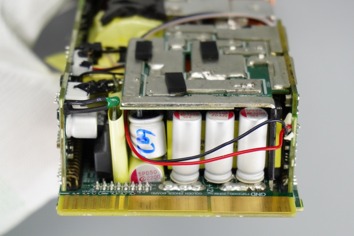
The output end houses solid-state filter caps, rectifier MOSFETs with heat-shrink tubing for insulation, while the vertical PCB and filter caps are wrapped with tape for insulation.
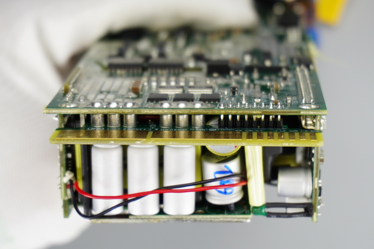
The PCBA module and PCB edge-connector are connected by soldered copper posts.
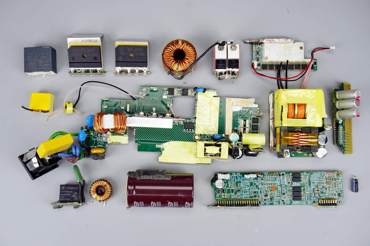
Desolder and remove the filter inductor and safety X2 cap, then cut the PCB to remove the bridge rectifier and other components for further teardown.
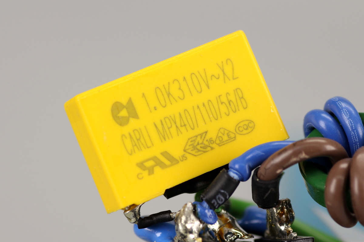
The safety X2 cap comes from CARLI and is rated at 1μF.
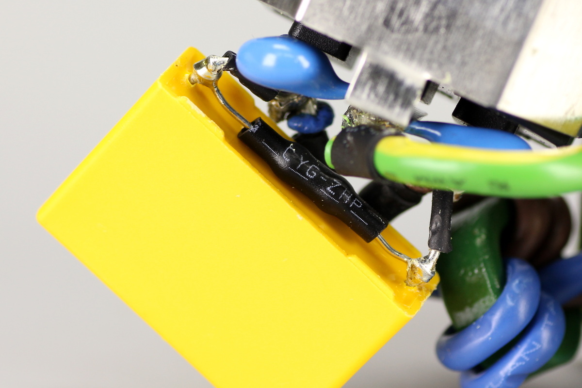
The X-cap discharge resistor is covered with heat-shrink tubing for insulation.
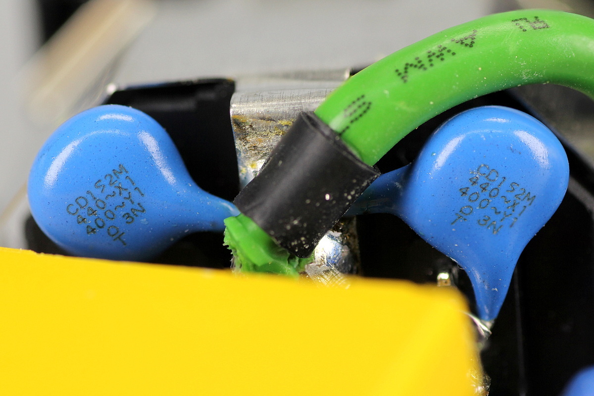
The Y-caps come from TDK, model CD152M.
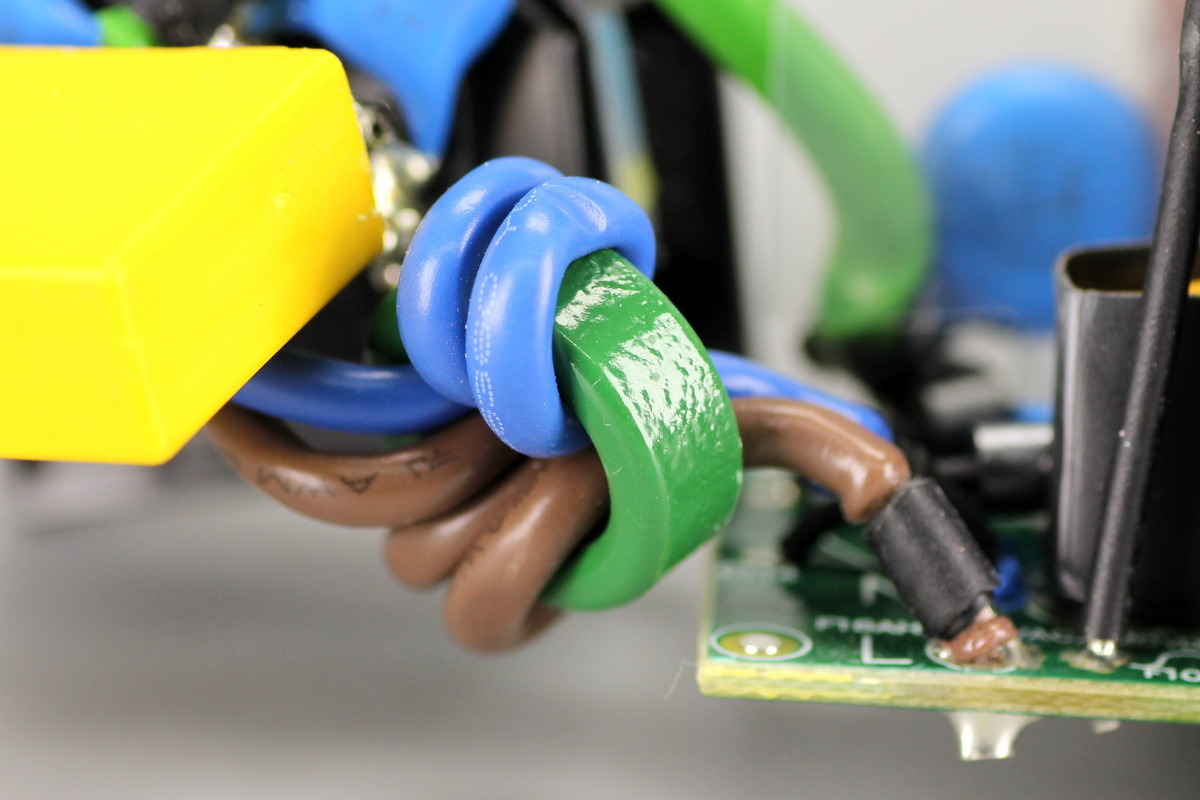
The power wires pass through a ferrite core to suppress high-frequency interference.
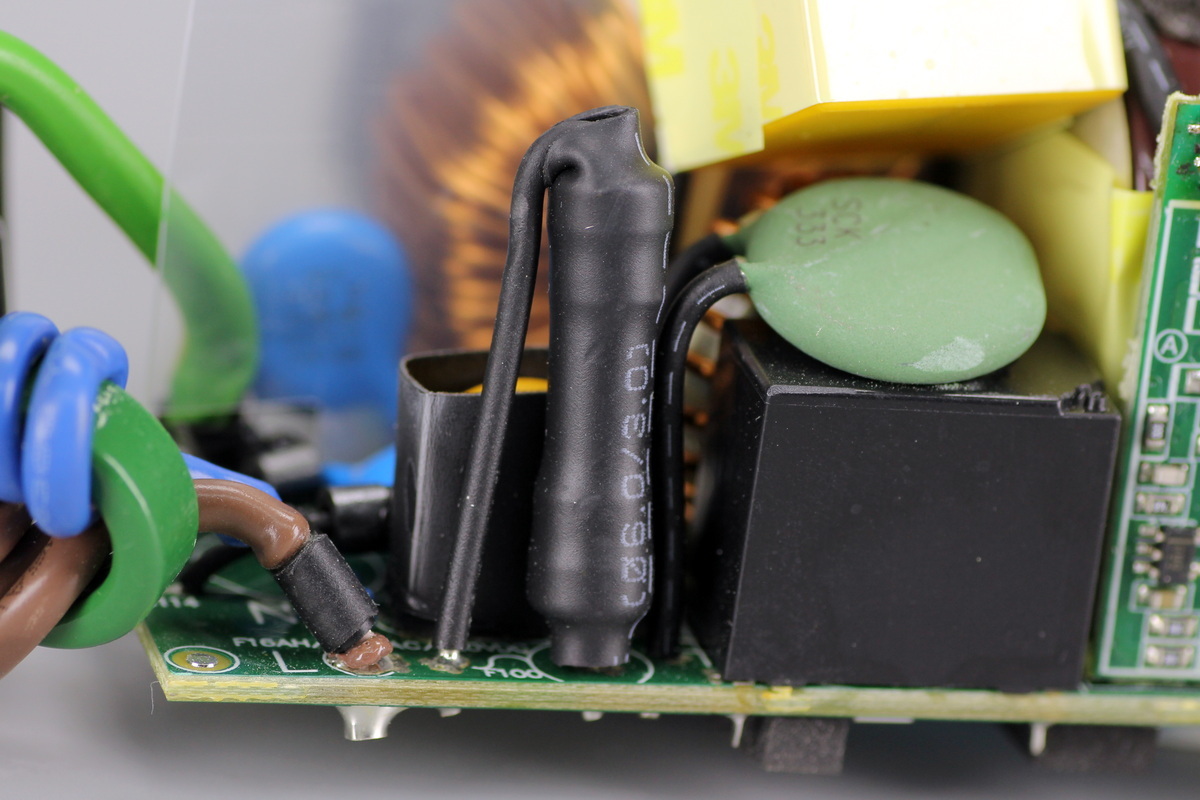
The fuse is covered with heat-shrink tubing for insulation.
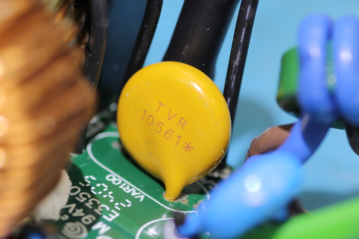
The varistor is marked TVR10561 and is used to absorb overvoltage surges.
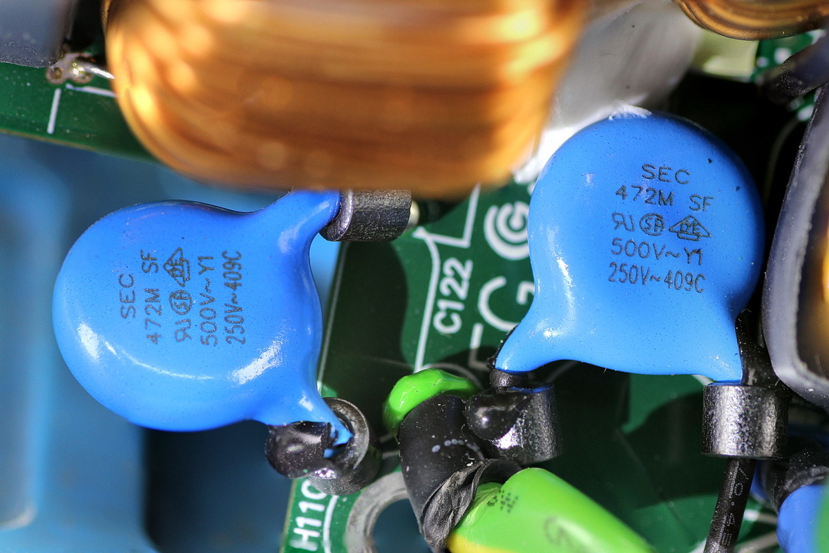
The Y-caps come from SEC, model 472M.
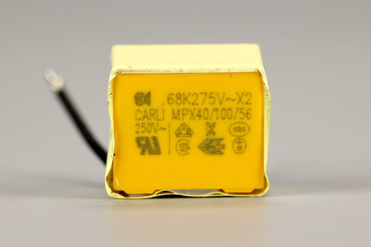
The safety X2 cap comes from CARLI and is rated at 0.68μF.
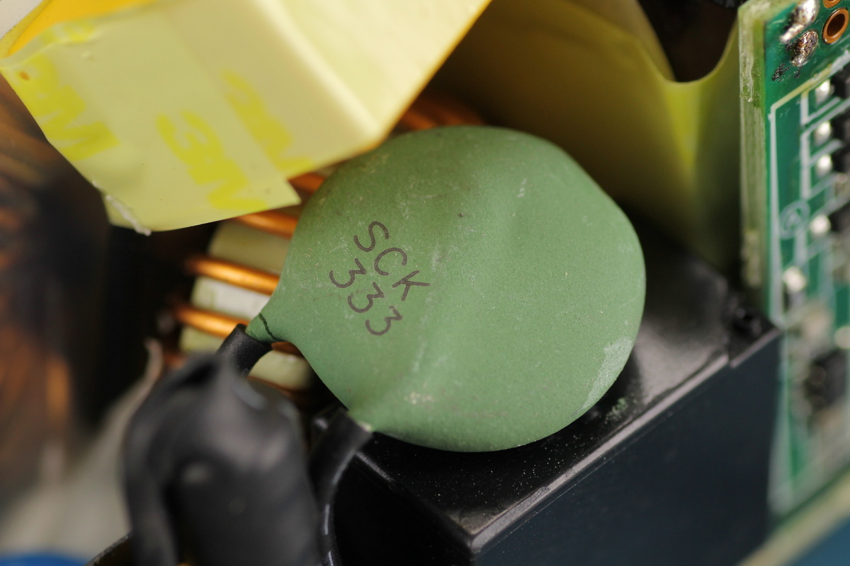
The thermistor is marked SCK 333.
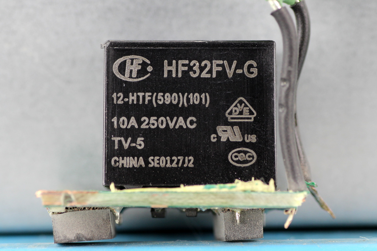
The relay comes from Hongfa, model HF32FV-G/12-HTF, which is an ultra-miniature power relay with one normally open contact, a 10A contact switching capacity, and a 12V coil voltage.
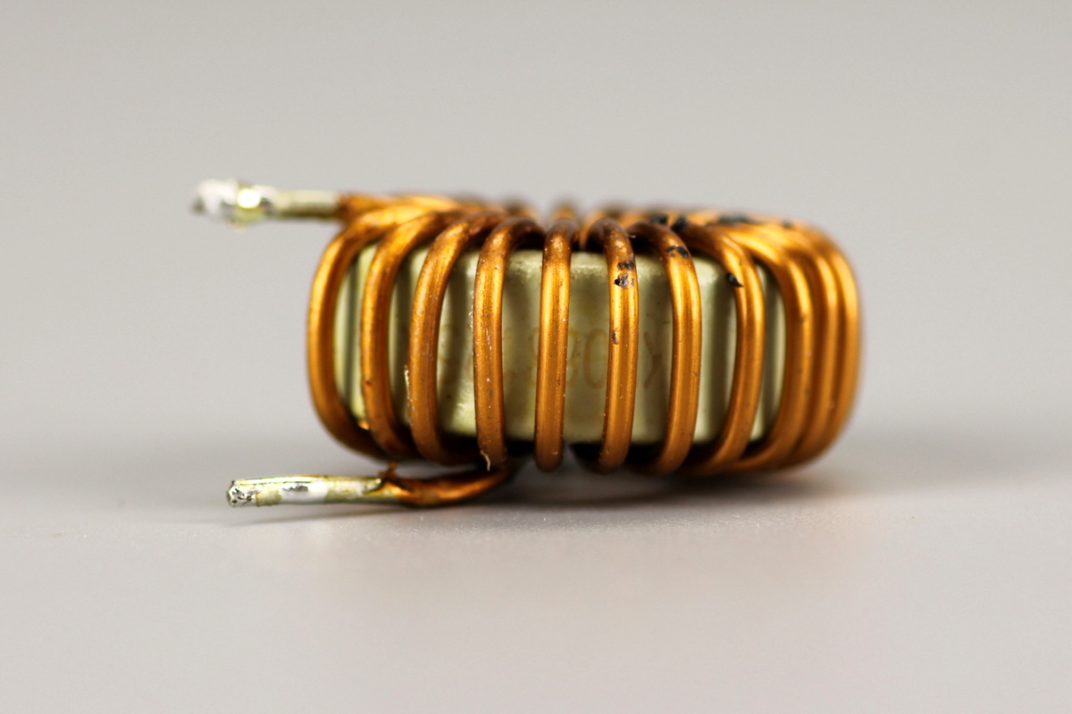
The filter choke is wound with enameled wire.
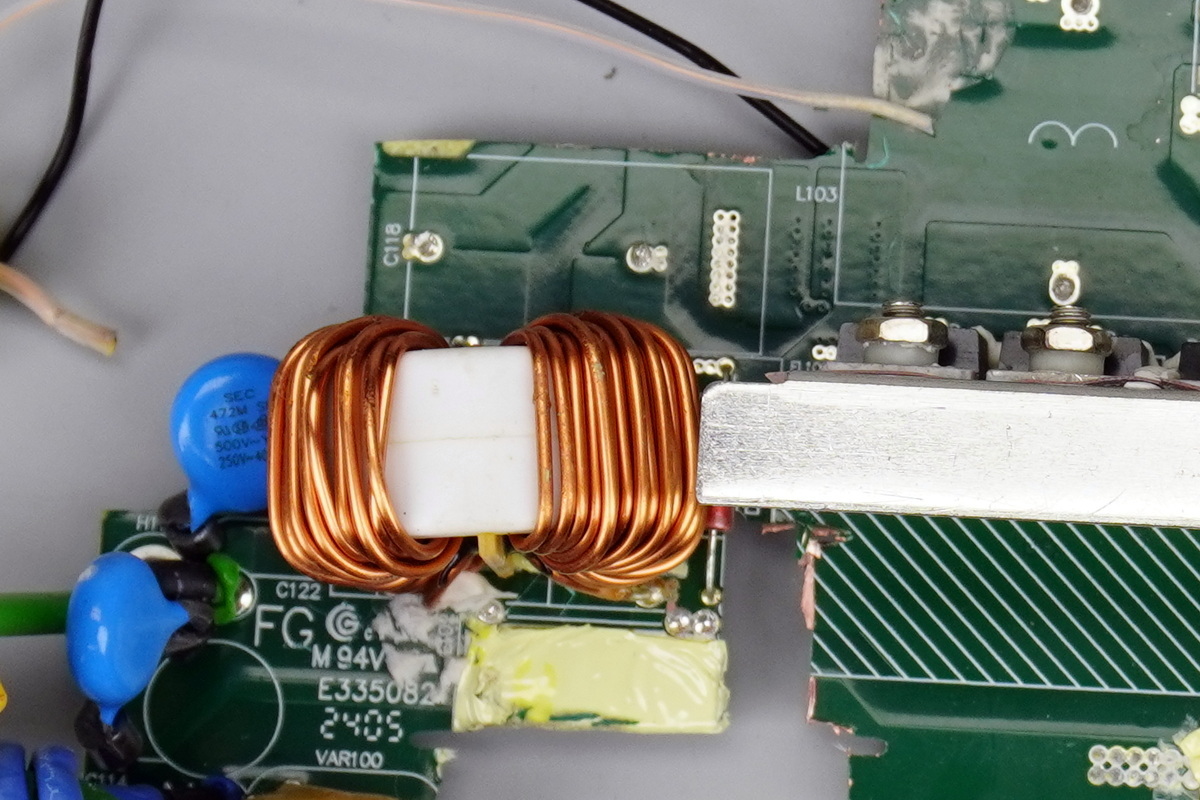
The common-mode choke is wound with enameled wire.
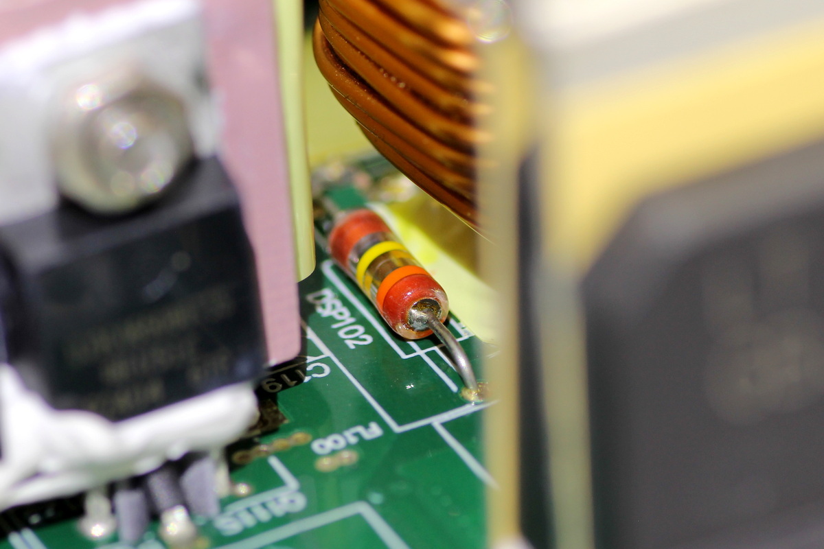
A gas discharge tube is located beside the common-mode choke.
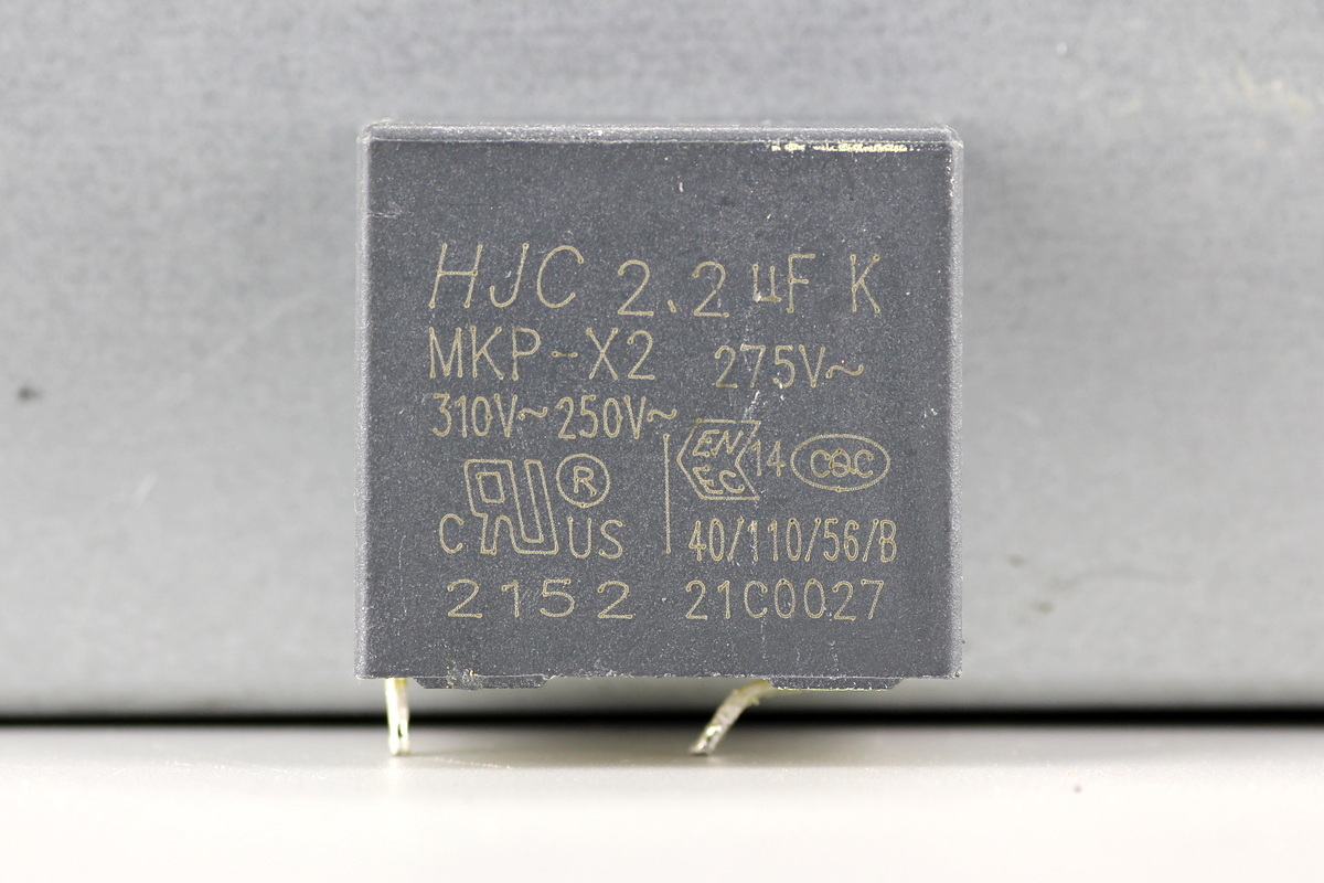
The safetyX2 cap comes from HJC and is rated at 2.2μF.
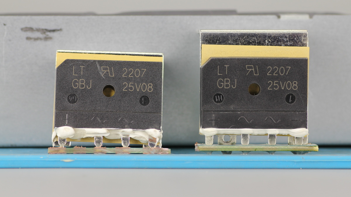
The bridge rectifier comes from DIODES, model GBJ25V08, which is a low-forward-voltage bridge rectifier rated at 800V 25A and comes in a GBJ package. Two are used in parallel.
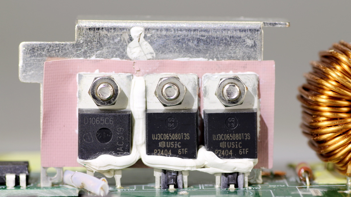
The heat sink carries the PFC switching MOSFETs and a PFC rectifier MOSFET.
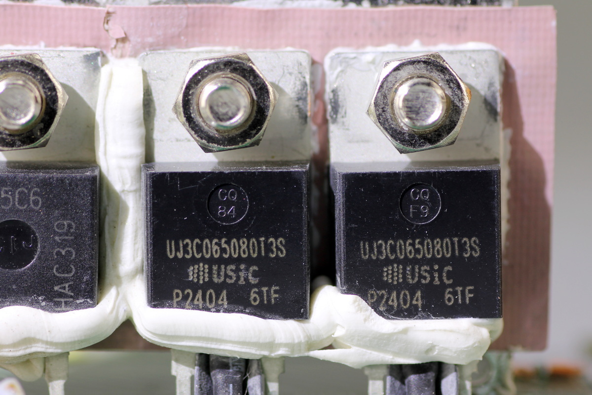
The PFC switching MOSFET comes from onsemi, model UJ3C065080T3S, which is a cascode SiC junction field-effect transistor rated at 650V with an on-resistance of 80mΩ and comes in a TO-220 package.
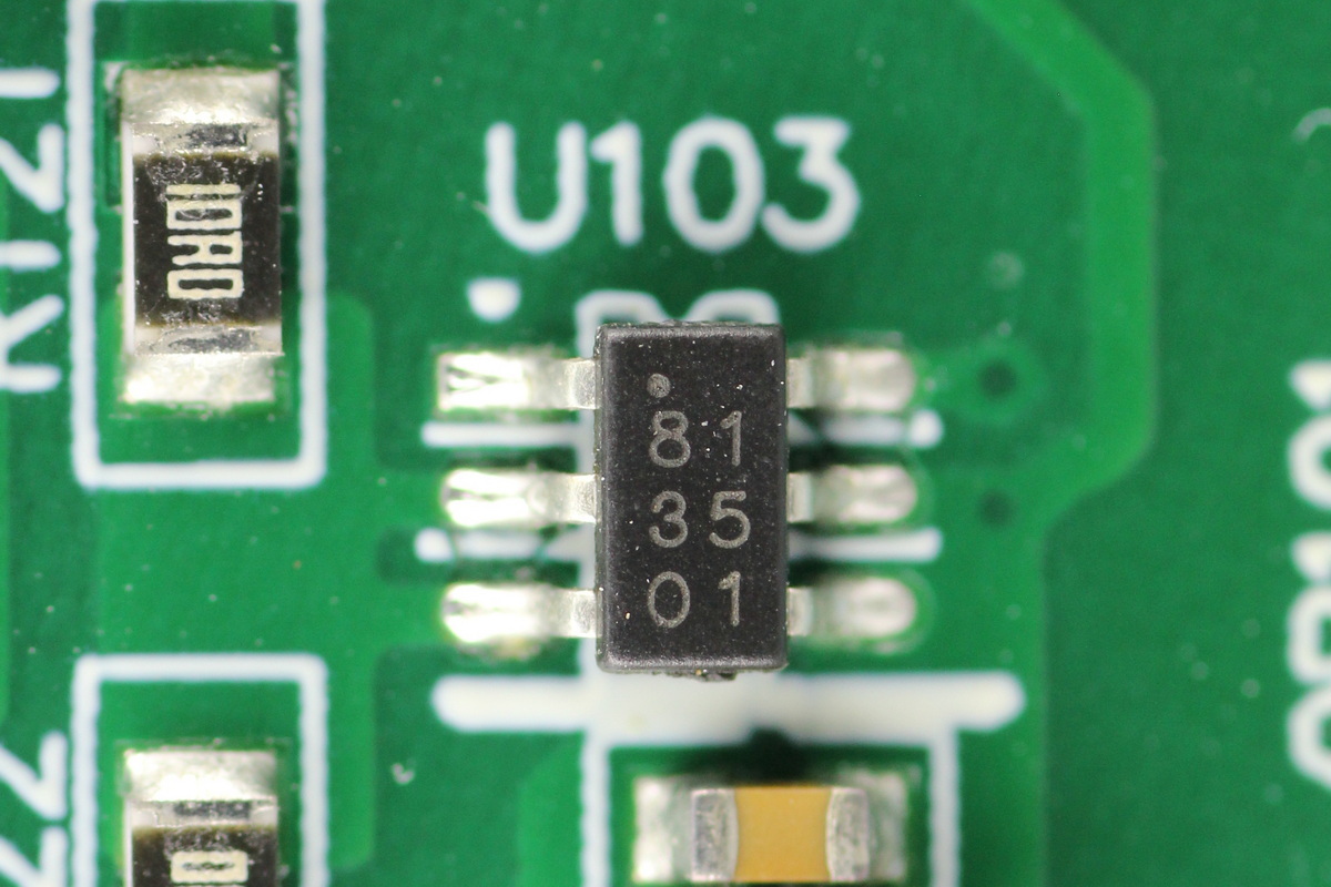
The driver comes from Infineon, marked 81, model 1EDN8511B, which is a single-channel low-side gate driver supporting 4A source current and 8A sink current, and comes in a SOT23-6 package.
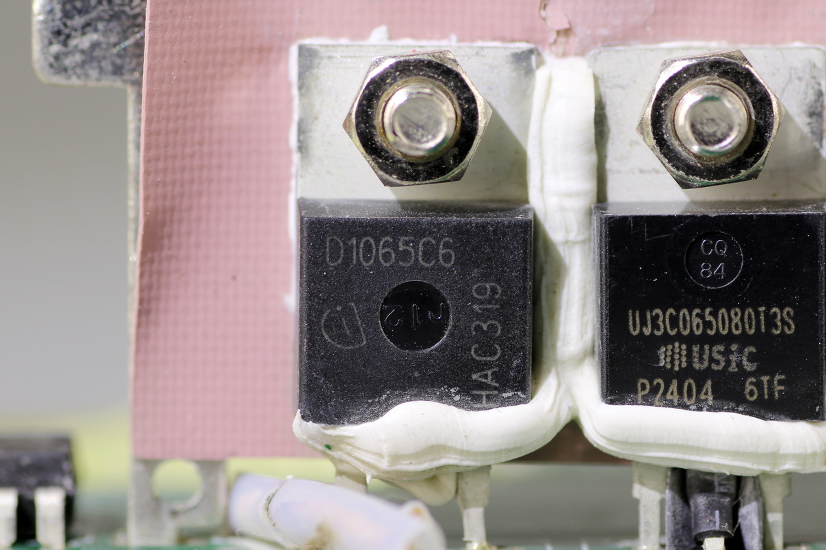
The PFC rectifier MOSFET comes from Infineon, marked D1065C6, model IDH10G65C6, which is a sixth-generation SiC Schottky diode rated at 650V 10A and comes in a TO220-2 package.
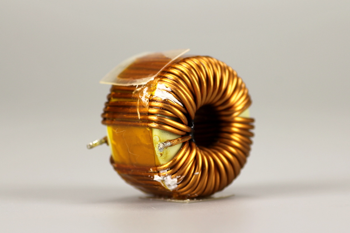
The PFC boost choke is wound with enameled wire around a magnetic ring core.
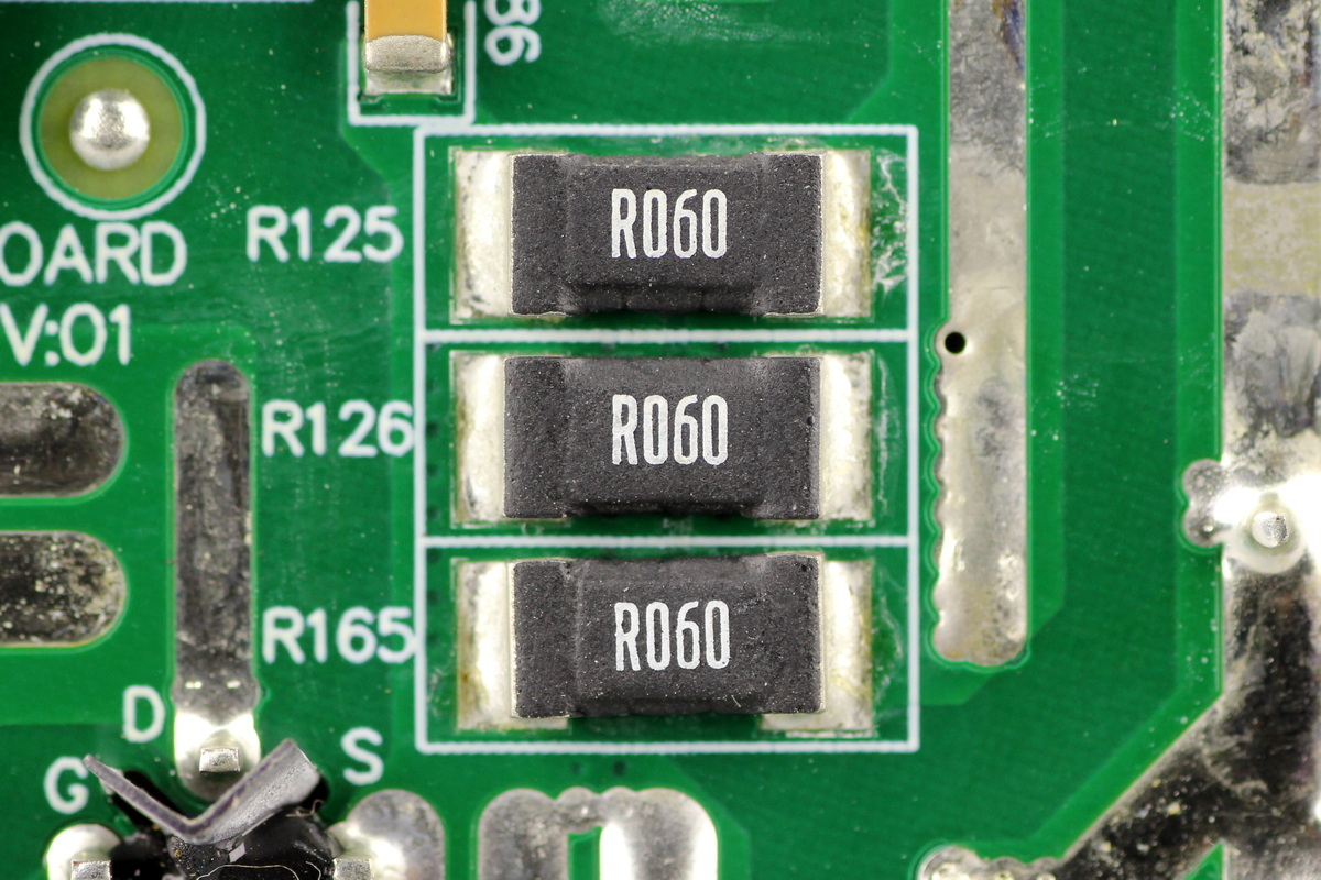
Three 60mΩ resistors are connected in parallel to sense the current through the PFC switching MOSFET.
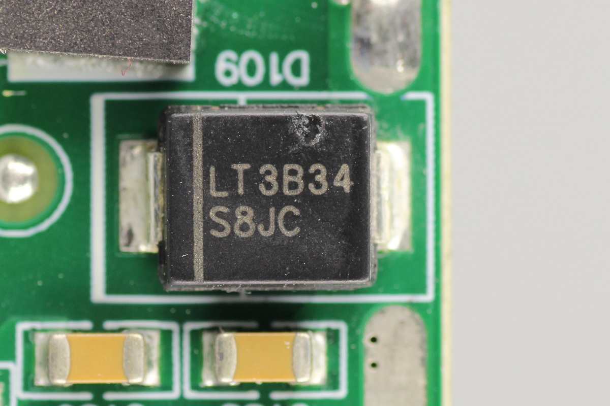
The bypass diode comes from DIODES, model S8JC, which is rated at 600V 8A and comes in an SMC package.
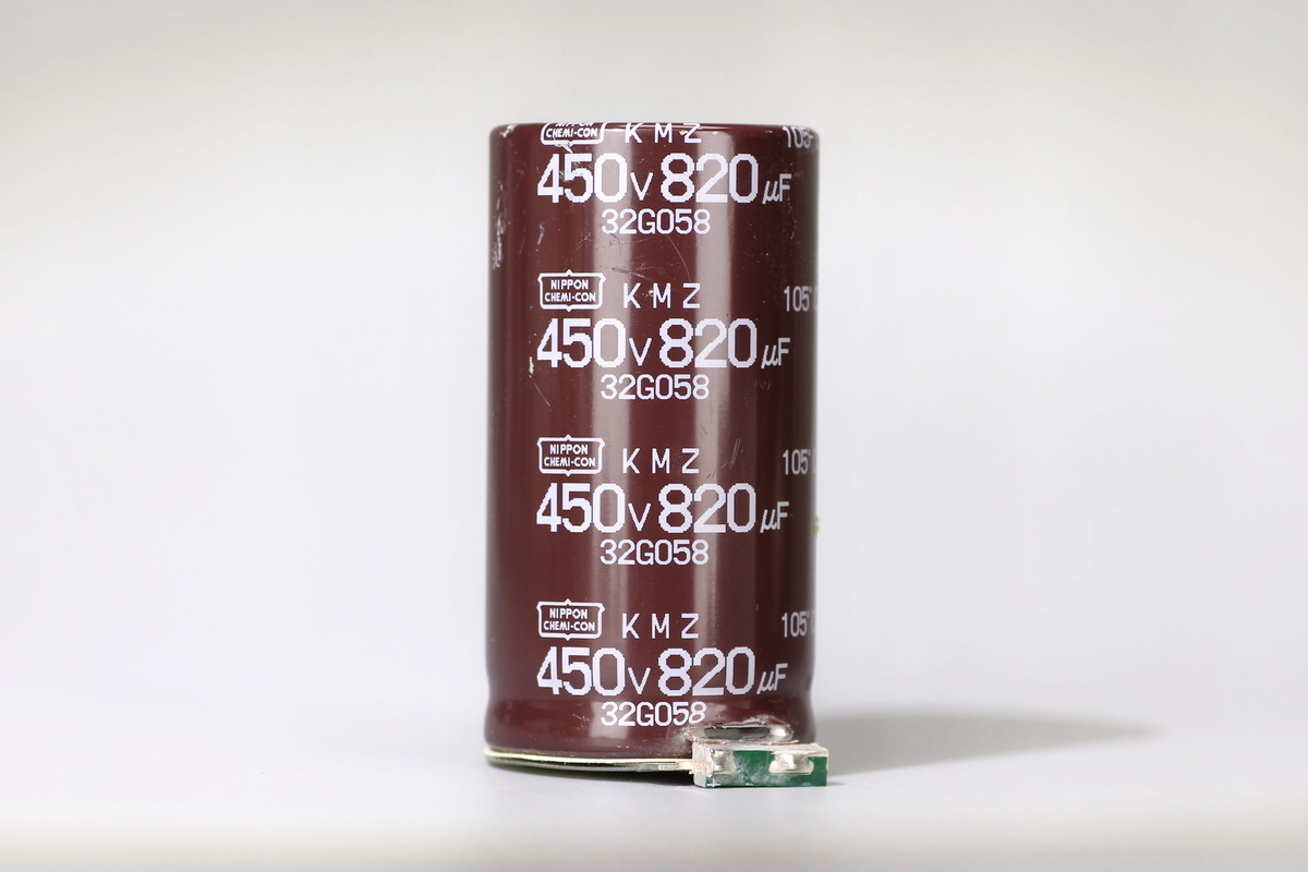
The high-voltage filter cap comes from NCC and belongs to the KMZ series of electrolytic caps, spec 450V 820μF.
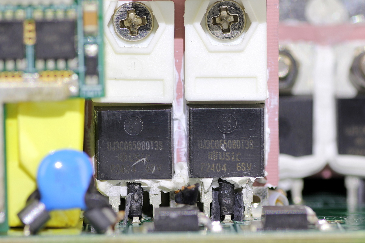
The phase-shifted full-bridge switching MOSFETs come from onsemi, model UJ3C065080T3S, the same model as the PFC switching MOSFET.
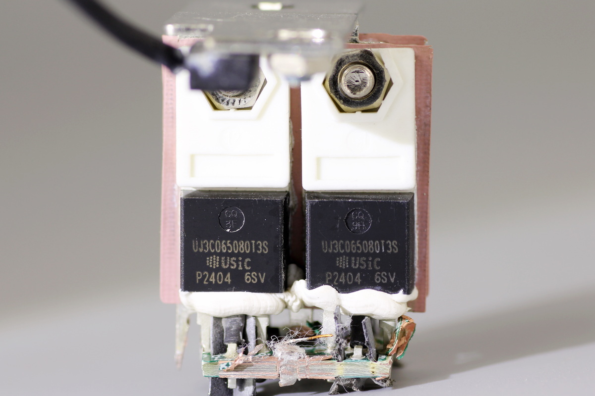
The two switching MOSFETs on the other side of the heat sink share the same model.
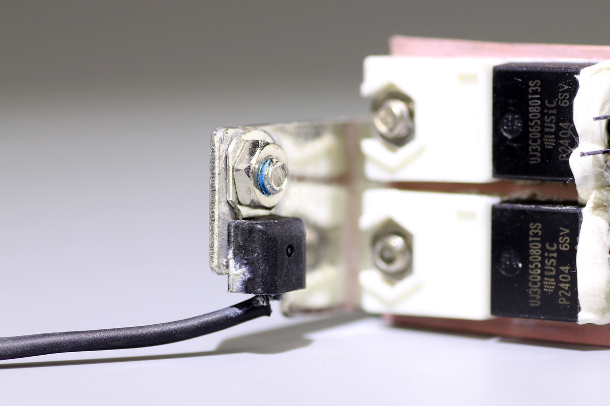
A thermistor is fixed to the heat sink for temperature monitoring.
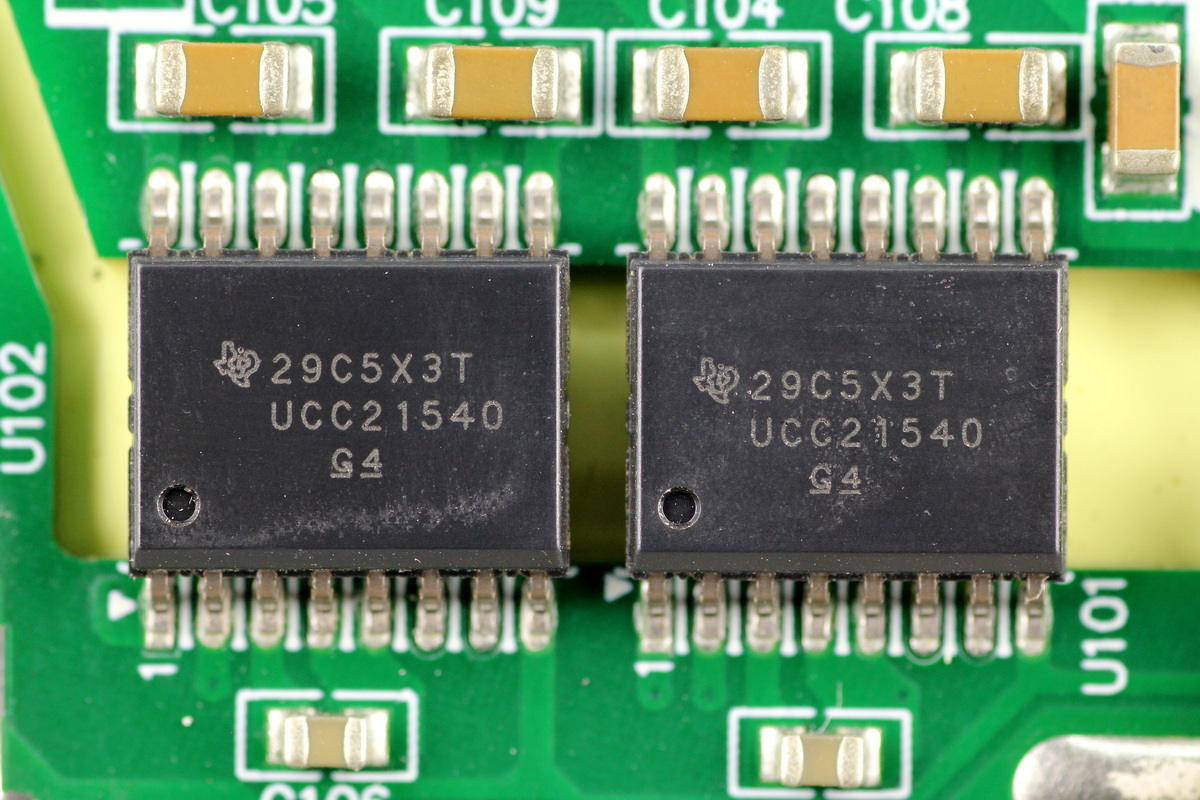
The driver comes from TI, model UCC21540, which is an enhanced isolated dual-channel gate driver with 4A/6A current capability, disable functionality, and programmable dead time. It supports GaN, IBGT, and silicon MOS applications and comes in an SOICDW16 package.
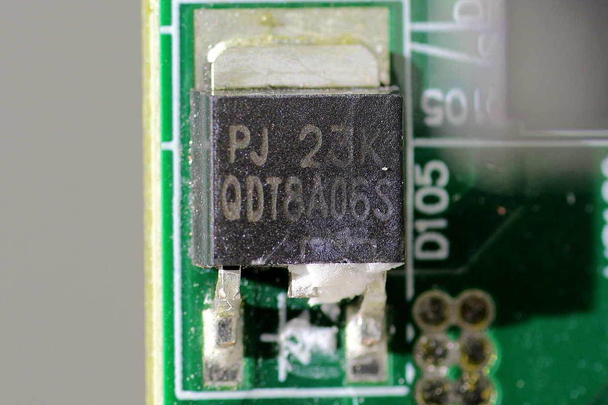
The diode comes from PANJIT, model QDT8A06S, which is an ultrafast recovery diode rated at 600V 8A and comes in a TO-252 package.
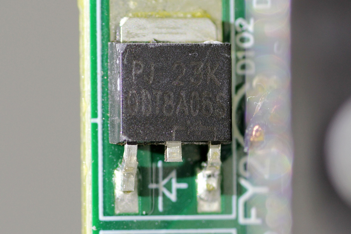
Another one shares the same model.
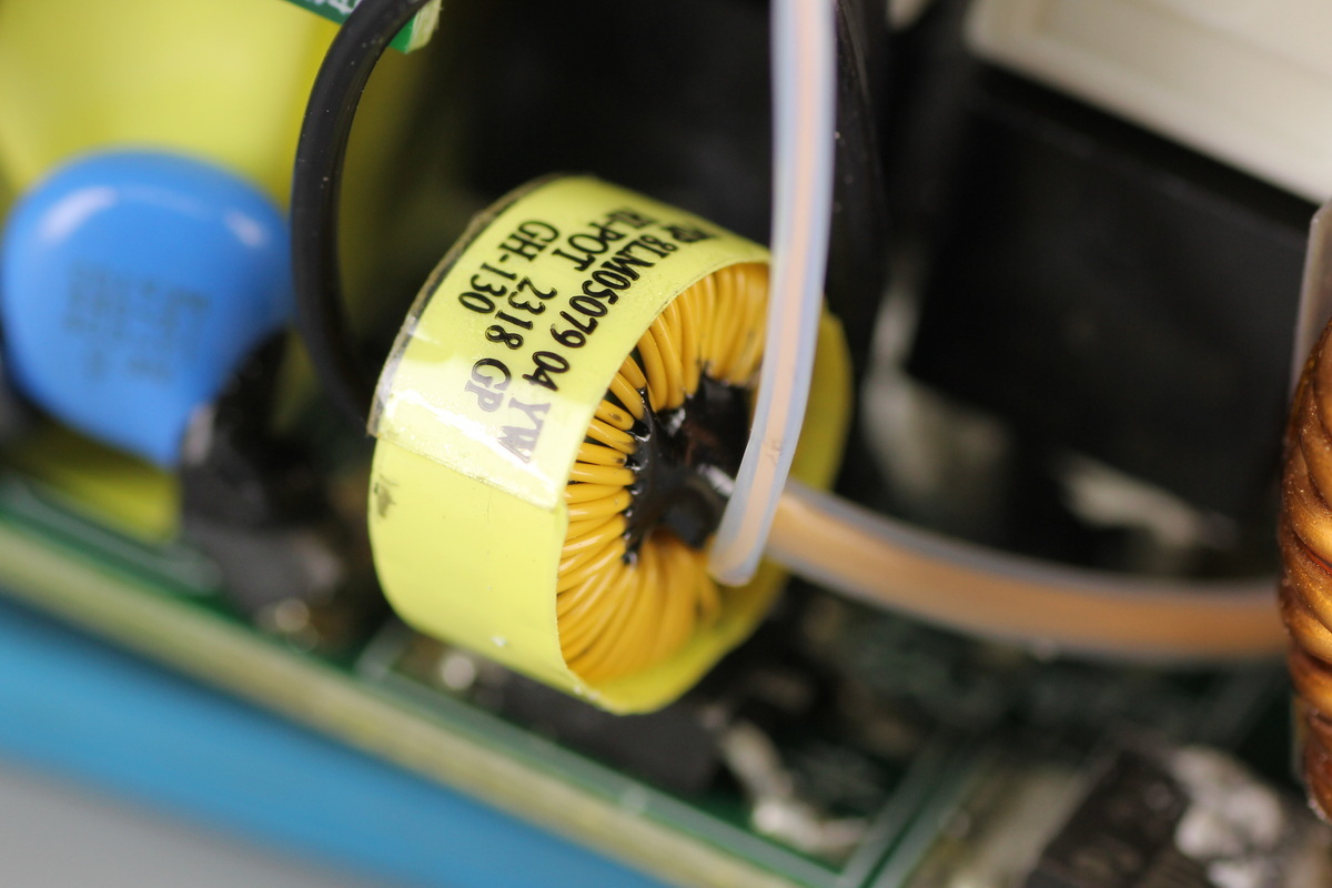
The current transformer used to detect the transformer primary current.
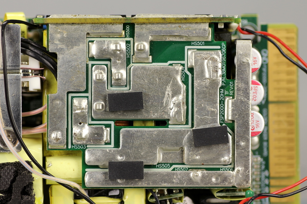
The transformer, resonant inductor, and synchronous rectifier PCB are connected by soldered copper bars.
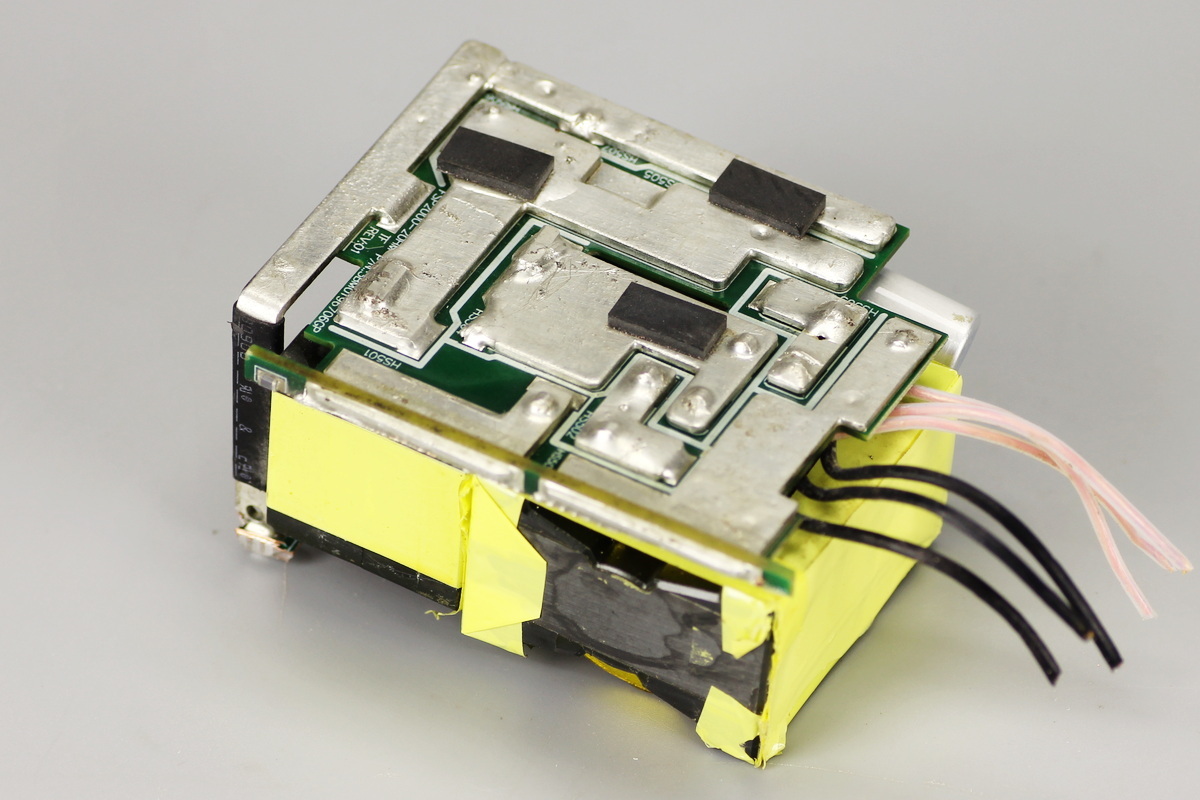
On the other side, a copper bar also connects to the synchronous rectifier PCB.
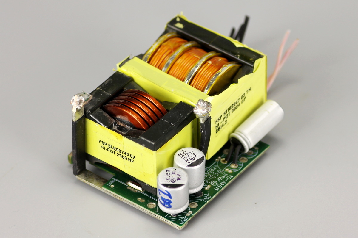
A PCB is soldered to the bottom of the transformer and resonant inductor, with filter caps mounted on it.
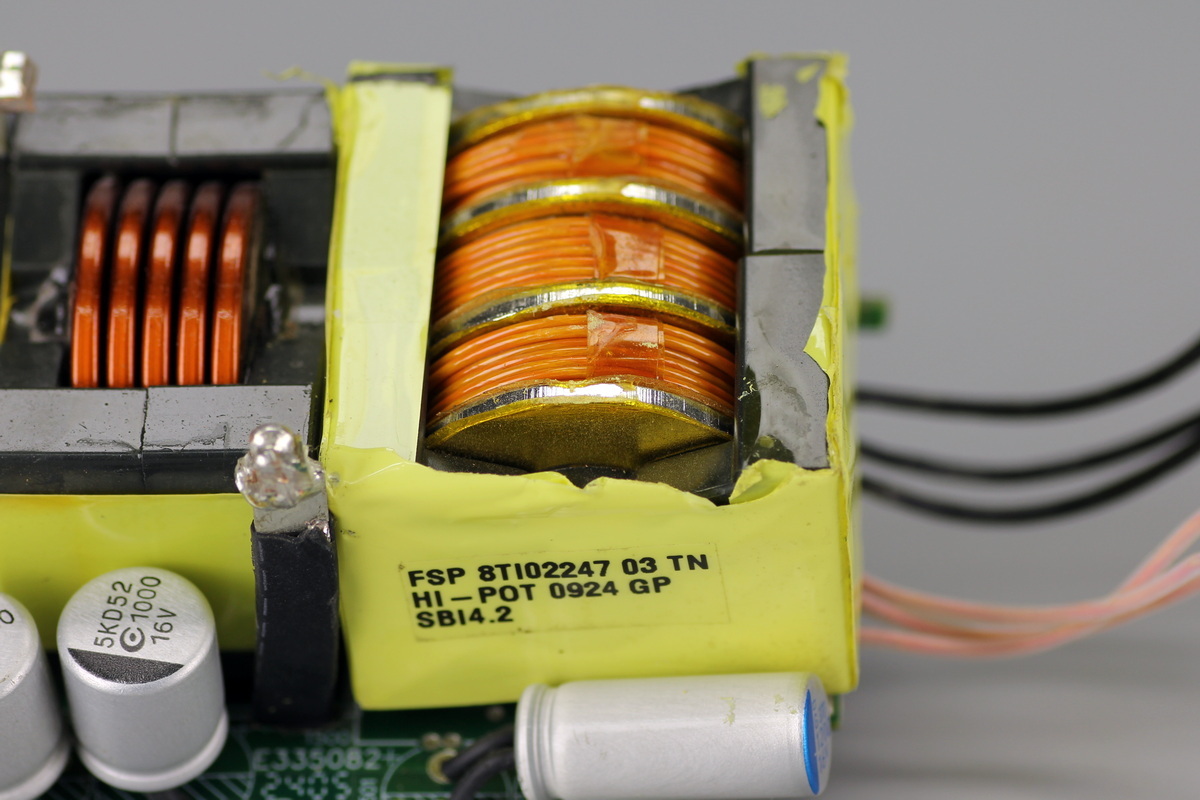
The transformer primary winding uses insulated wire, while the secondary side uses soldered copper sheets.
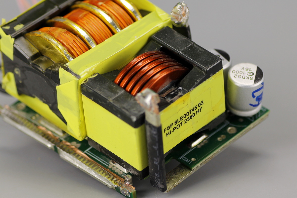
The resonant inductor is wound with flat copper wire.
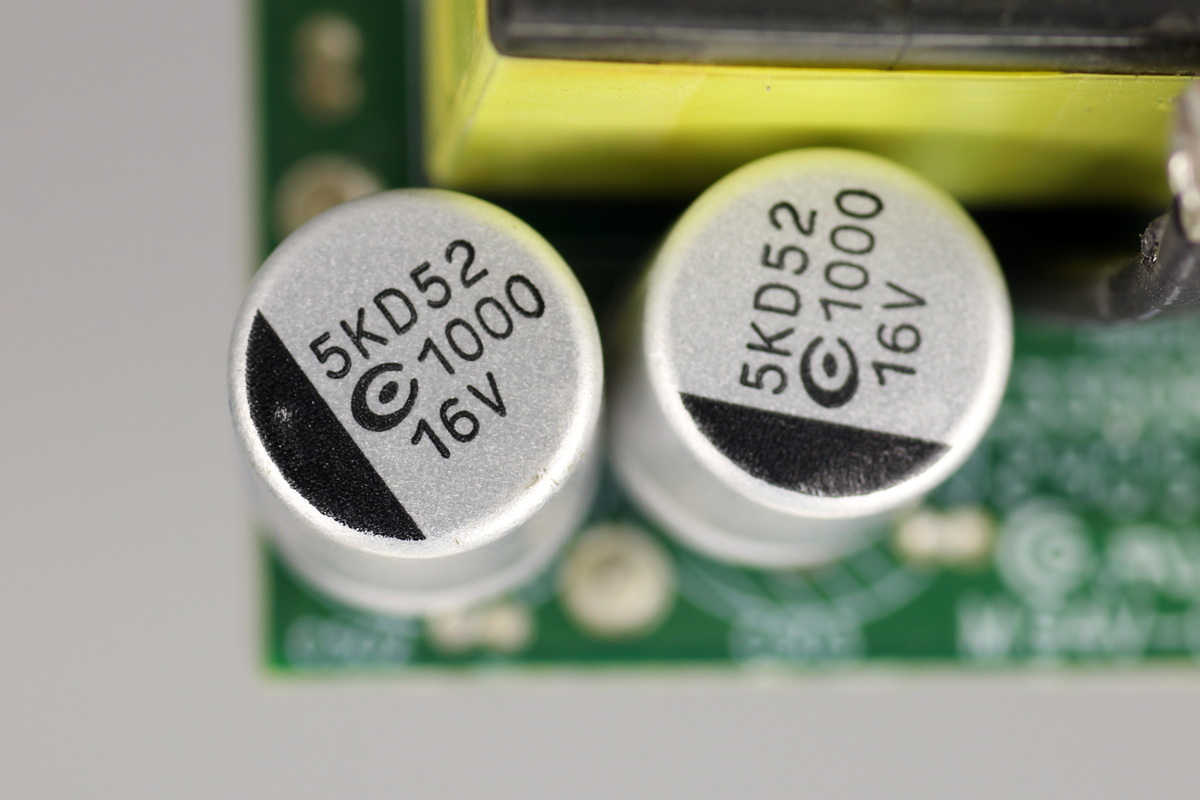
Two filter caps come from APAQ and are rated at 1000μF 16V.
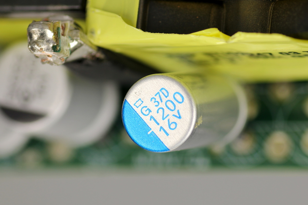
The filter cap comes from NCC and is rated at 1200μF 16V.

A synchronous rectifier PCB is soldered to the side of the transformer, which carries the synchronous rectifier MOSFETs and an NTC thermistor.
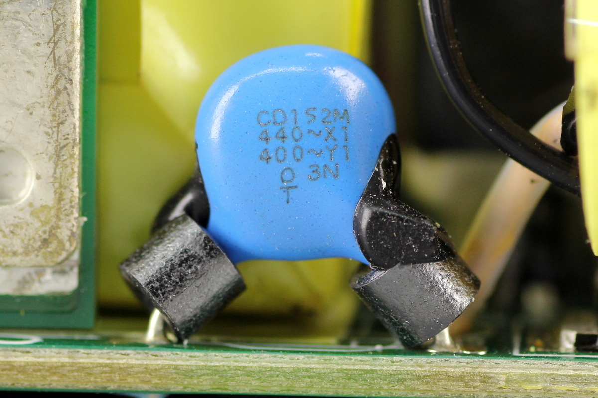
A Y-cap is soldered at the lower-right corner of the PCB, which comes from TDK, model CD152M.
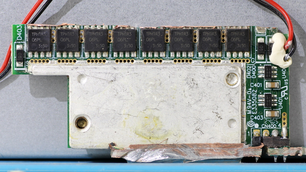
The other side of the PCB carries the synchronous rectifier MOSFETs and drivers.
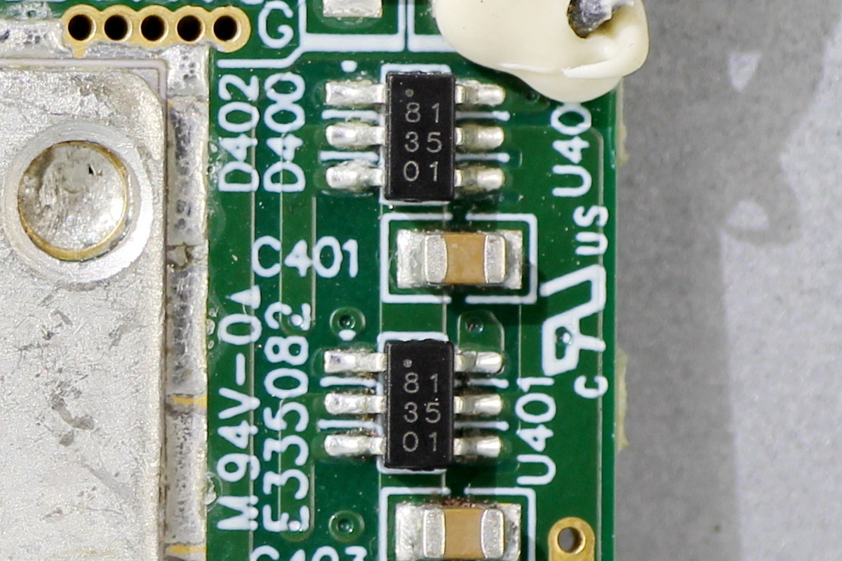
The driver is the Infineon 1EDN8511B.
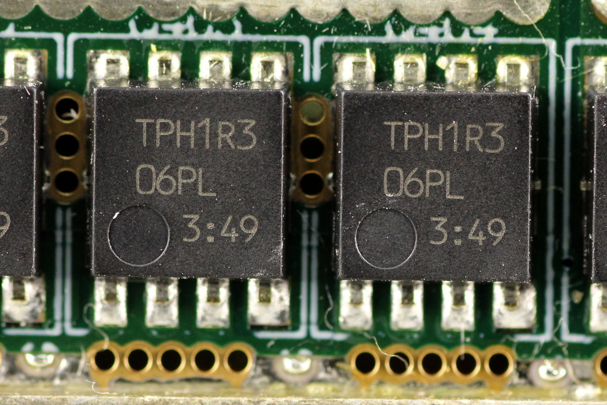
The synchronous rectifier MOSFETs come from TOSHIBA, model TPH1R306PL, NMOS, 60V and 1mΩ, and use the SOP Advance package. A total of 16 are used.
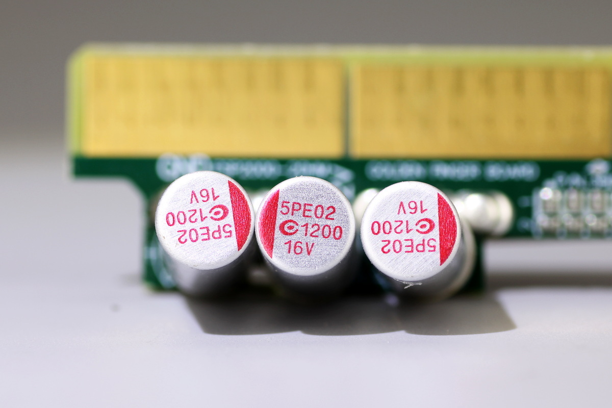
The output filter caps come from APAQ, spec 1200μF 16V.
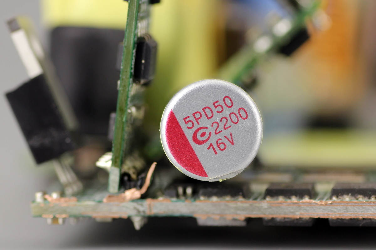
The filter cap is rated at 2200μF 16V.
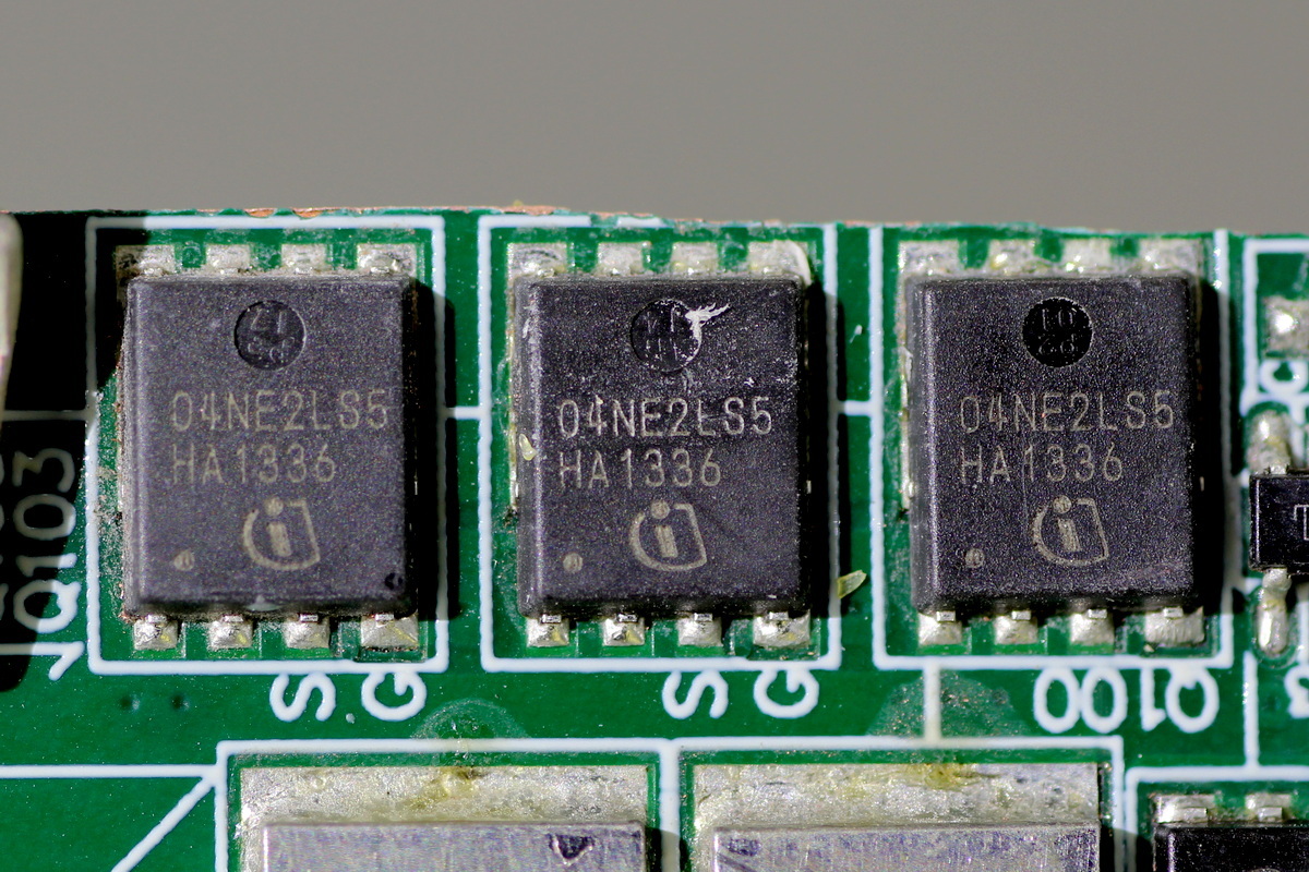
The output control MOSFETs come from Infineon, model BSC004NE2LS5, NMOS, 25V and 0.45mΩ, and in a TDSON-8 package.
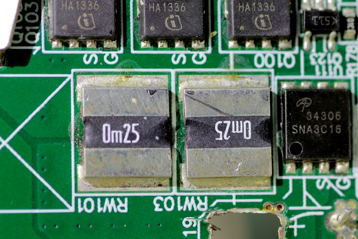
The current-sense resistors are rated at 0.25mΩ.
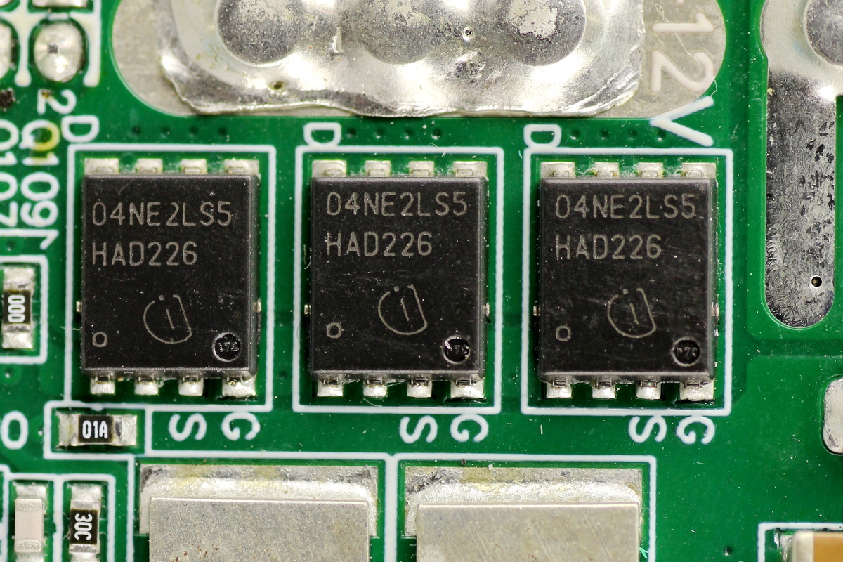
Three output control MOSFETs of the same model are located on the other side.
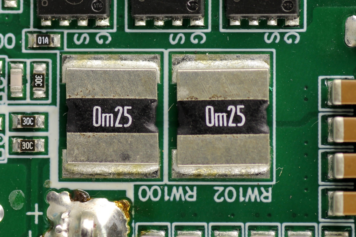
The current-sense resistors are rated at 0.25mΩ.
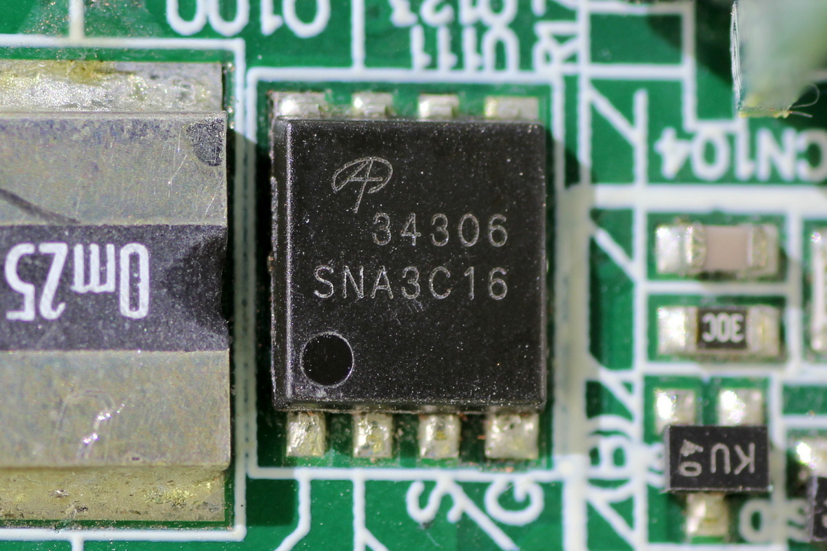
The output control MOSFET comes from AOS, model AONS34306, which is an NMOS device in a DFN5×6 package.
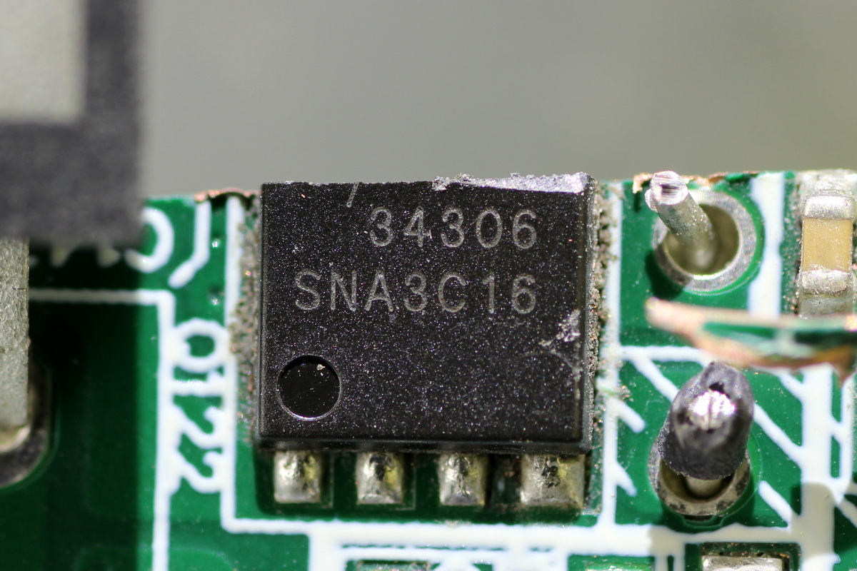
The other output control MOSFET is the same model.
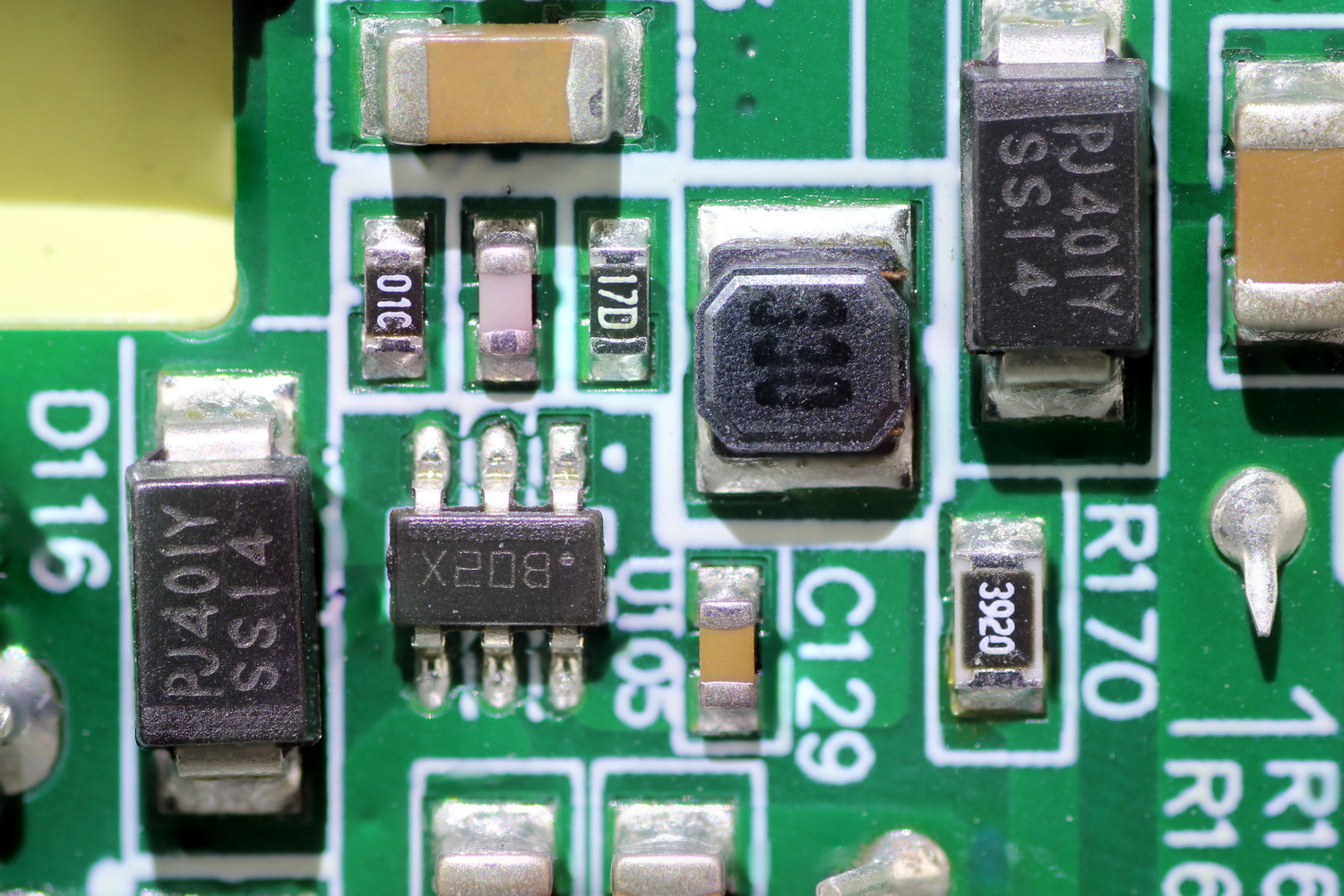
The buck converter comes from TI, marked B02X, model LMR14006, which supports a 4–40V input voltage range and delivers up to 600mA output current. It also features OCP and OTP and comes in a TSOT-6L package.
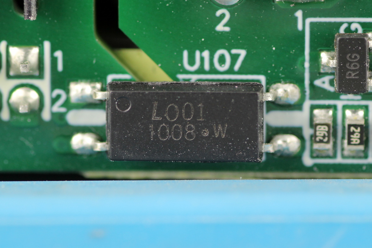
The optocoupler comes from LITEON, model LTV1008.
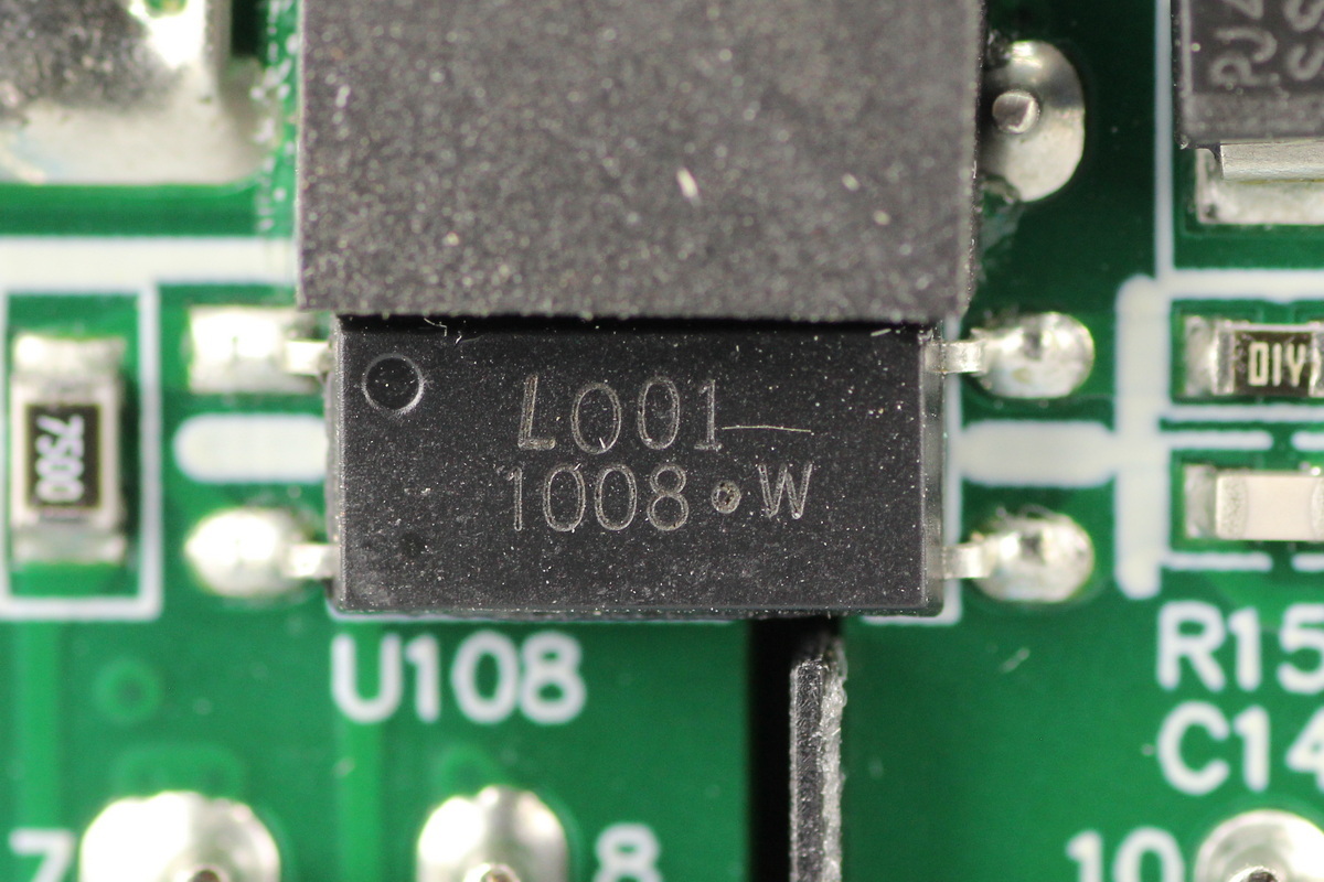
Another one shares the same model.
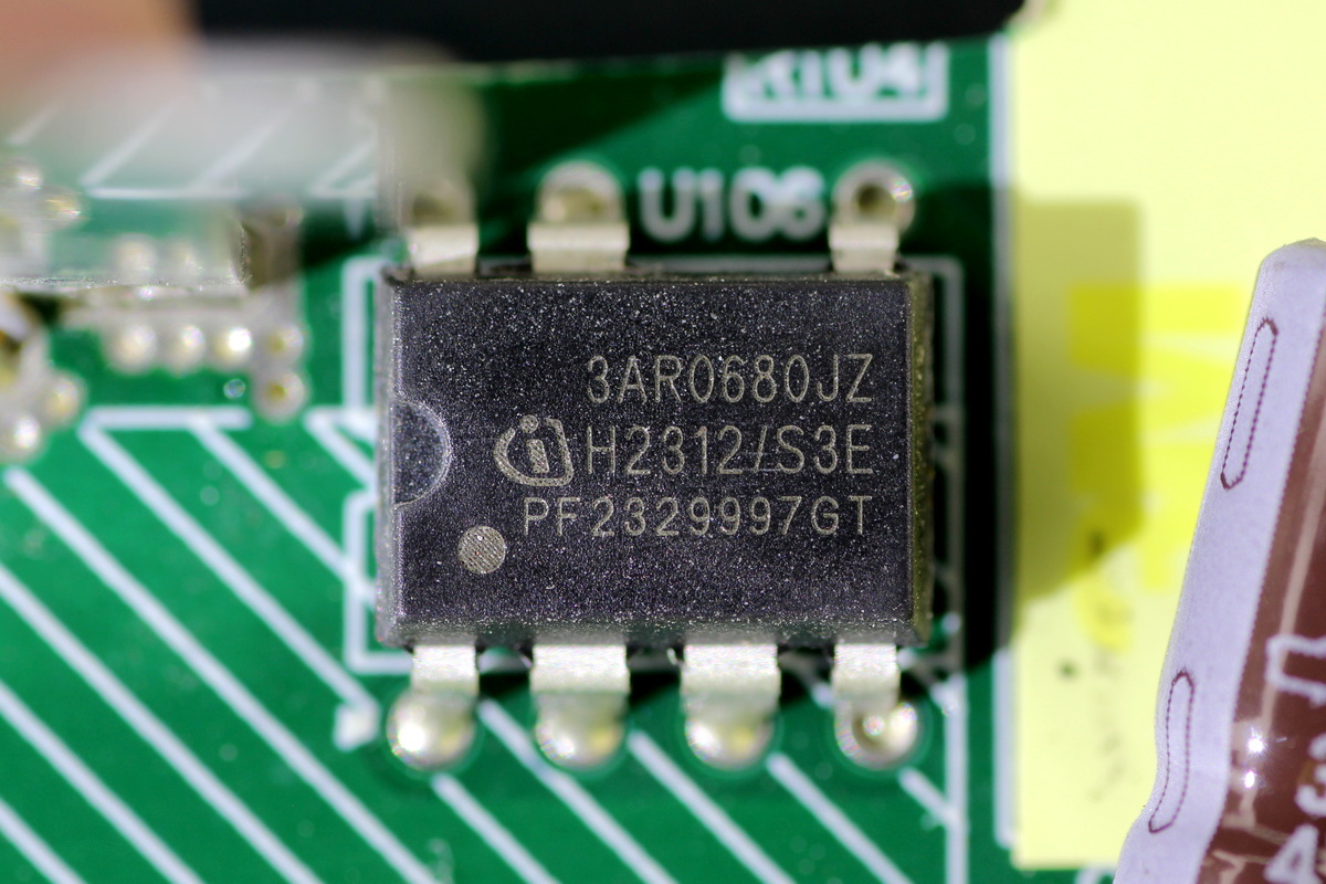
The standby power IC comes from Infineon, model ICE3AR0680JZ, which is a CoolSET™-F3R flyback AC-DC controller with an integrated 800V CoolMOS. It supports a 100kHz switching frequency and Active Burst Mode for low standby power consumption, and comes in a DIP-7 package.
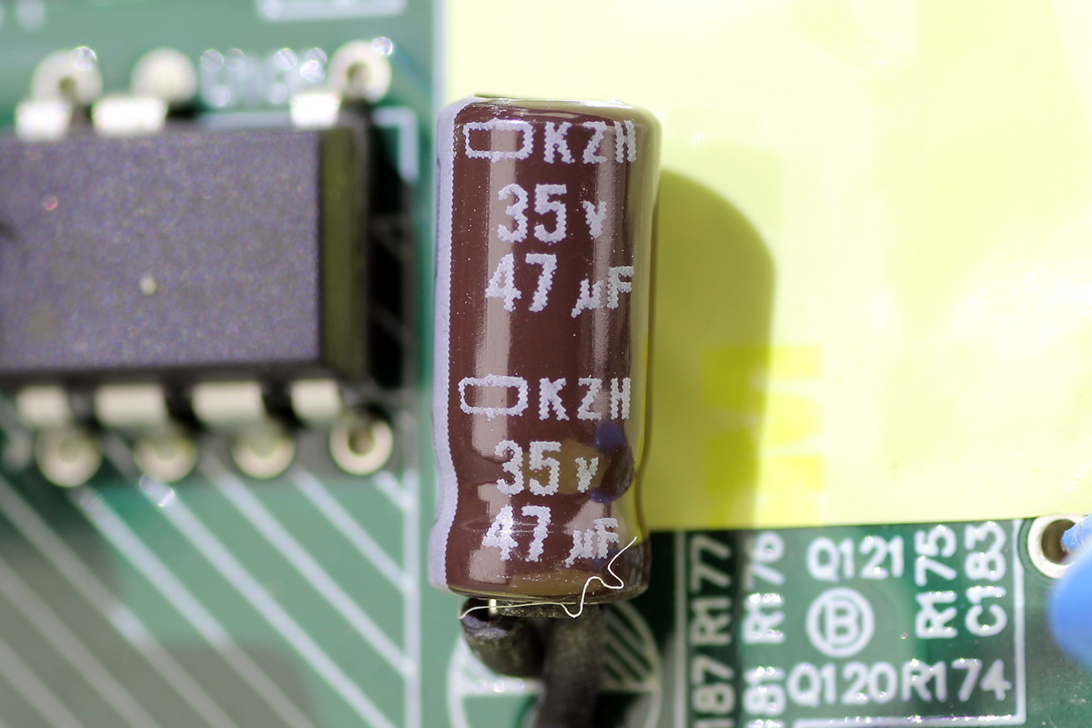
The filter cap supplying power to the master control chip comes from NCC and is rated at 35V 47μF.
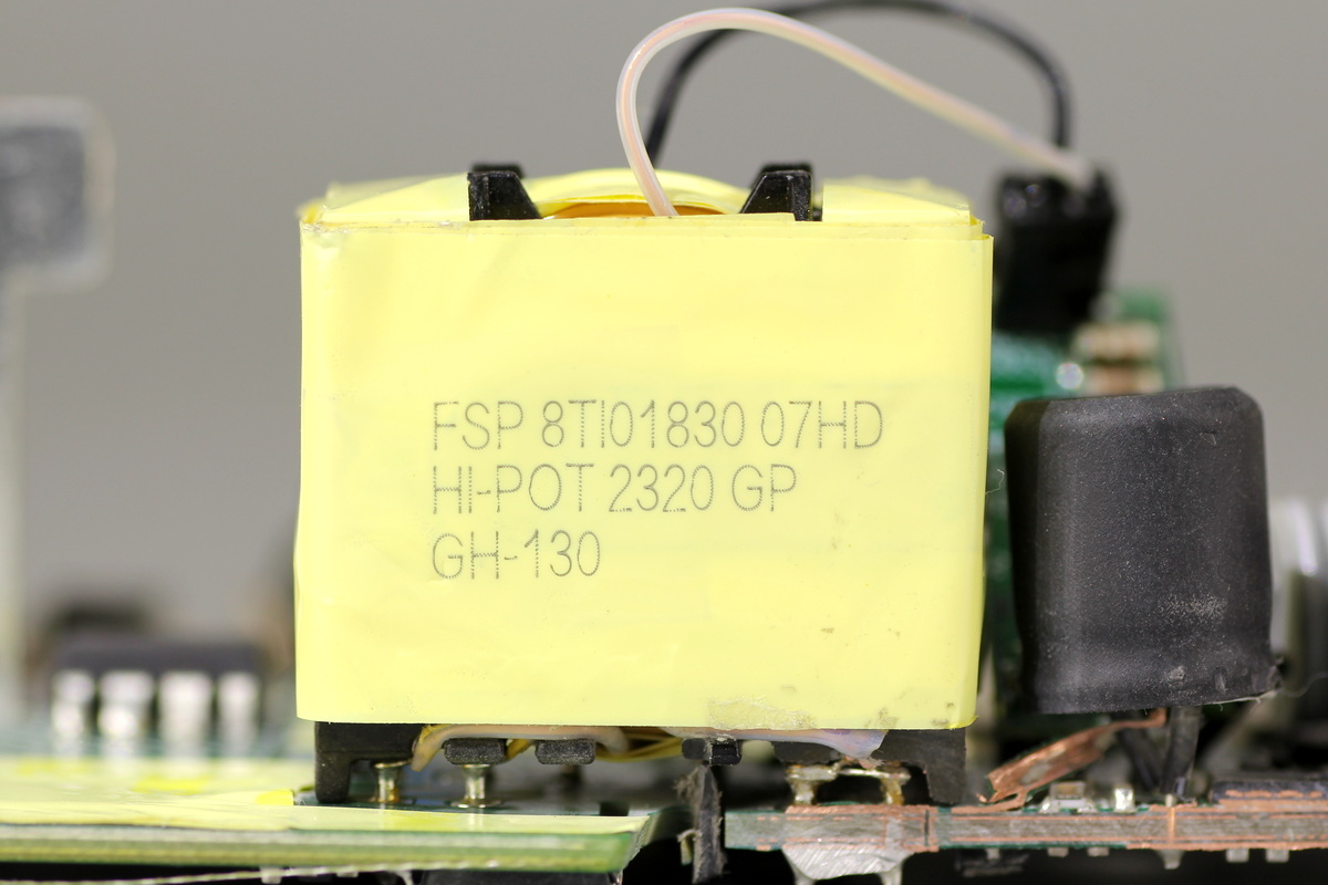
The transformer is tightly wrapped with insulating tape.
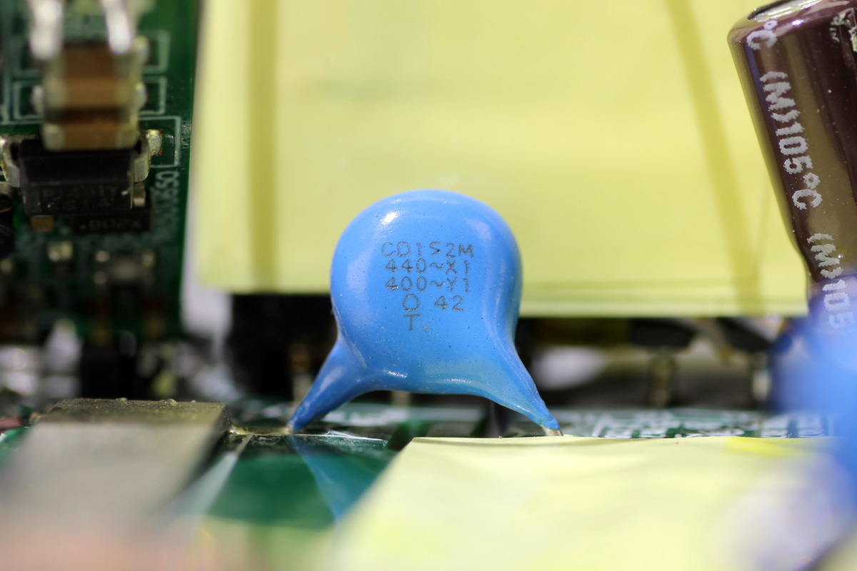
The blue Y-cap is marked CD152M.
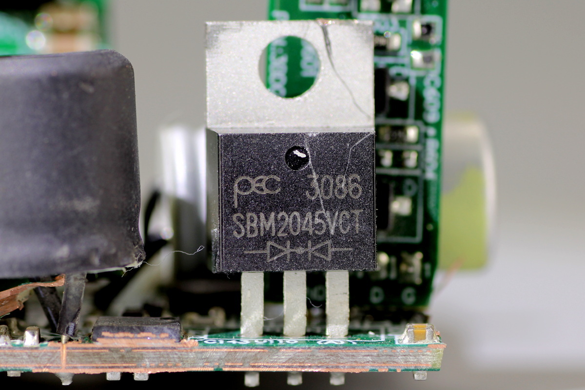
The rectifier diode comes from PANJIT, model SBM2045VCT, which is an ultra-low-forward-voltage Schottky diode rated at 45V 20A and comes in a TO-220AB package.
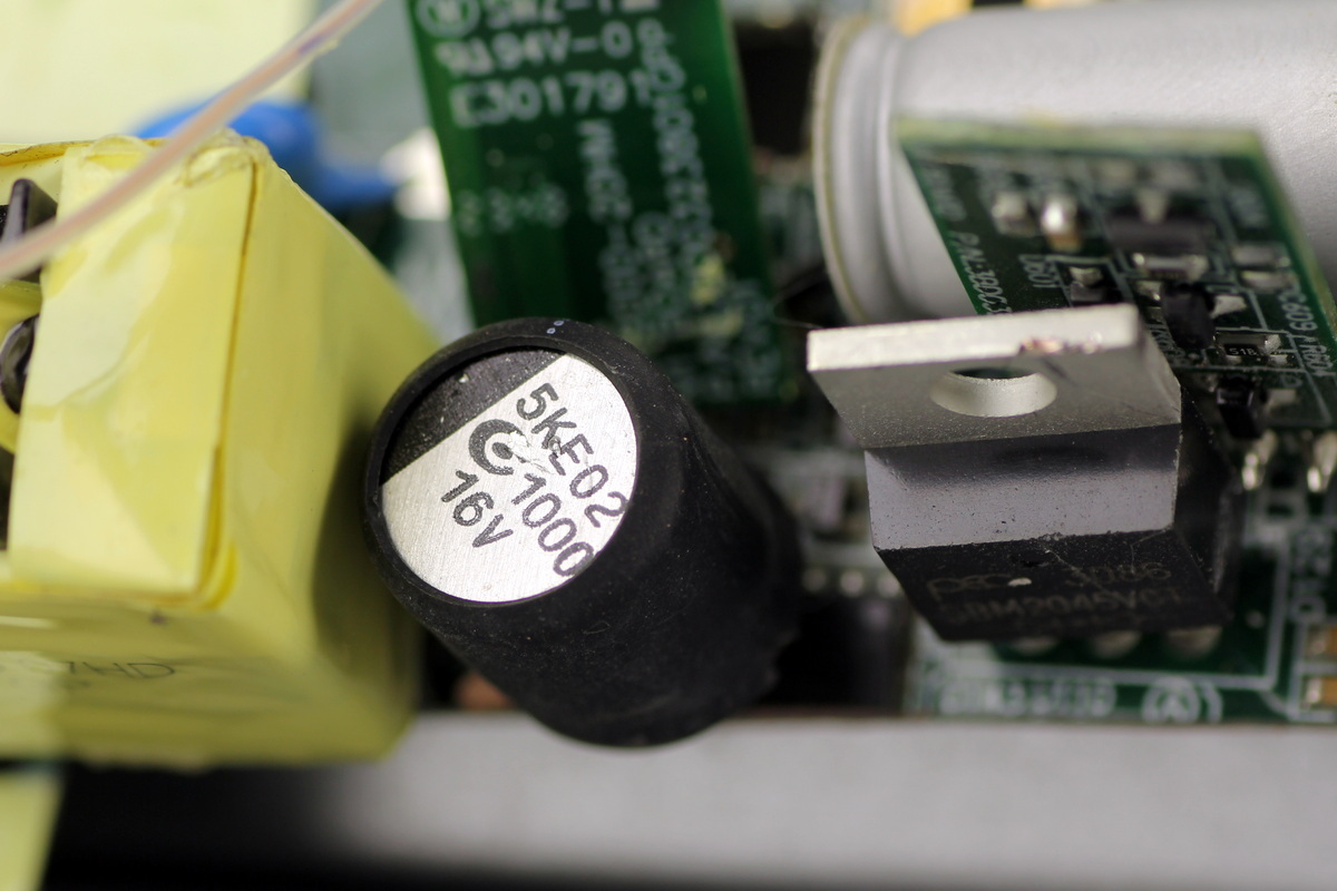
The filter cap comes from APAQ and is rated at 1000μF 16V.
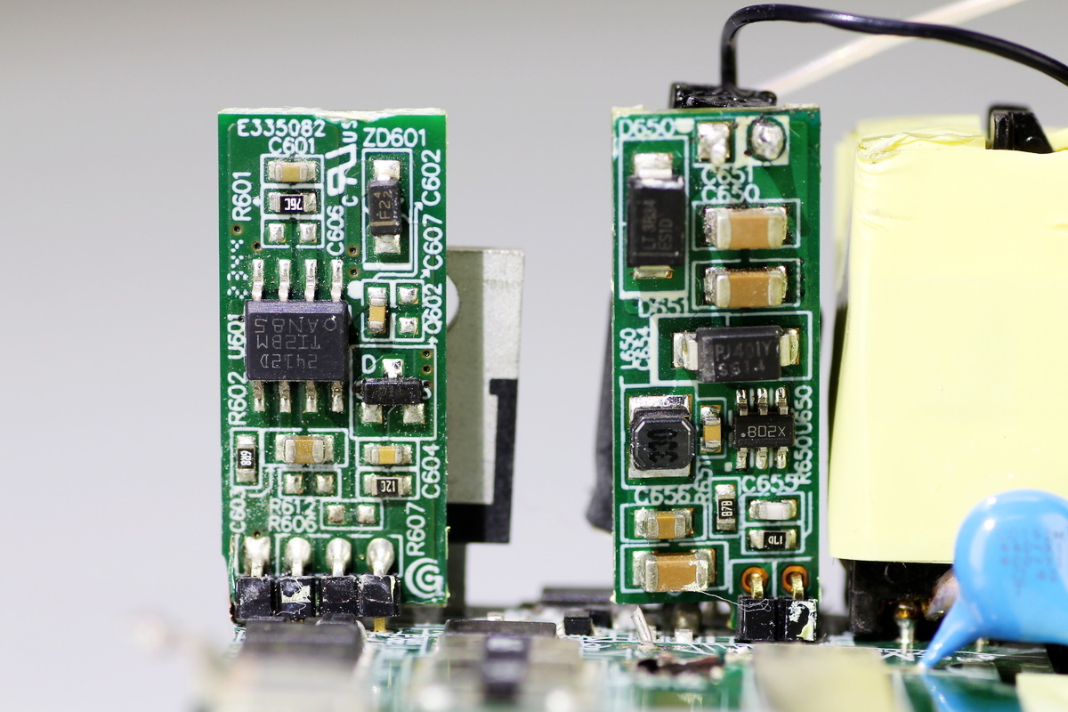
Two PCBs are soldered behind the rectifier diode and filter caps.
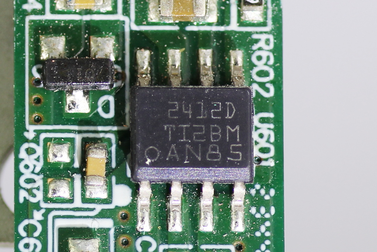
The ideal diode controller comes from TI, model TPS2412, which is used to control ORing diodes, supports a 3–16.5V operating voltage range, integrates a charge pump, and comes in an SOIC8 package.
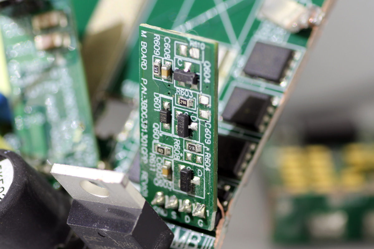
The back side of the PCB.
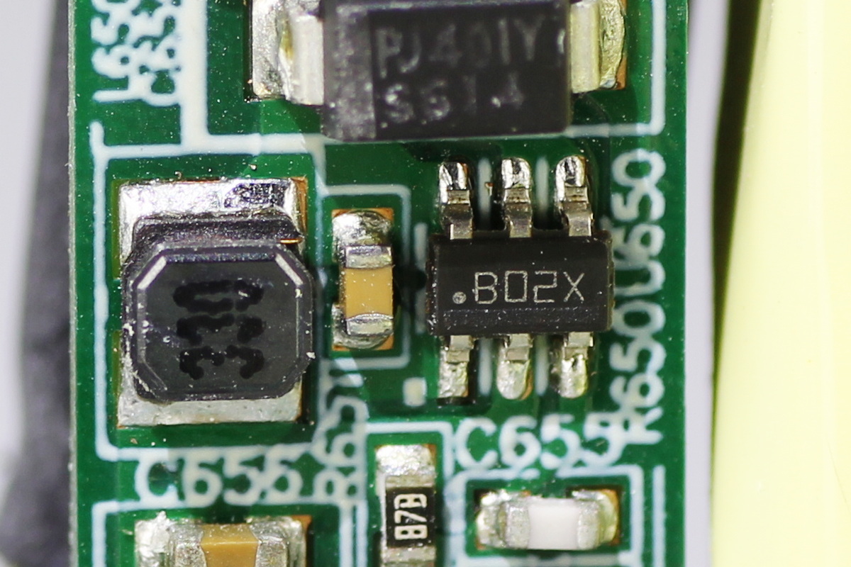
The other PCB features a TI LMR14006 buck converter.
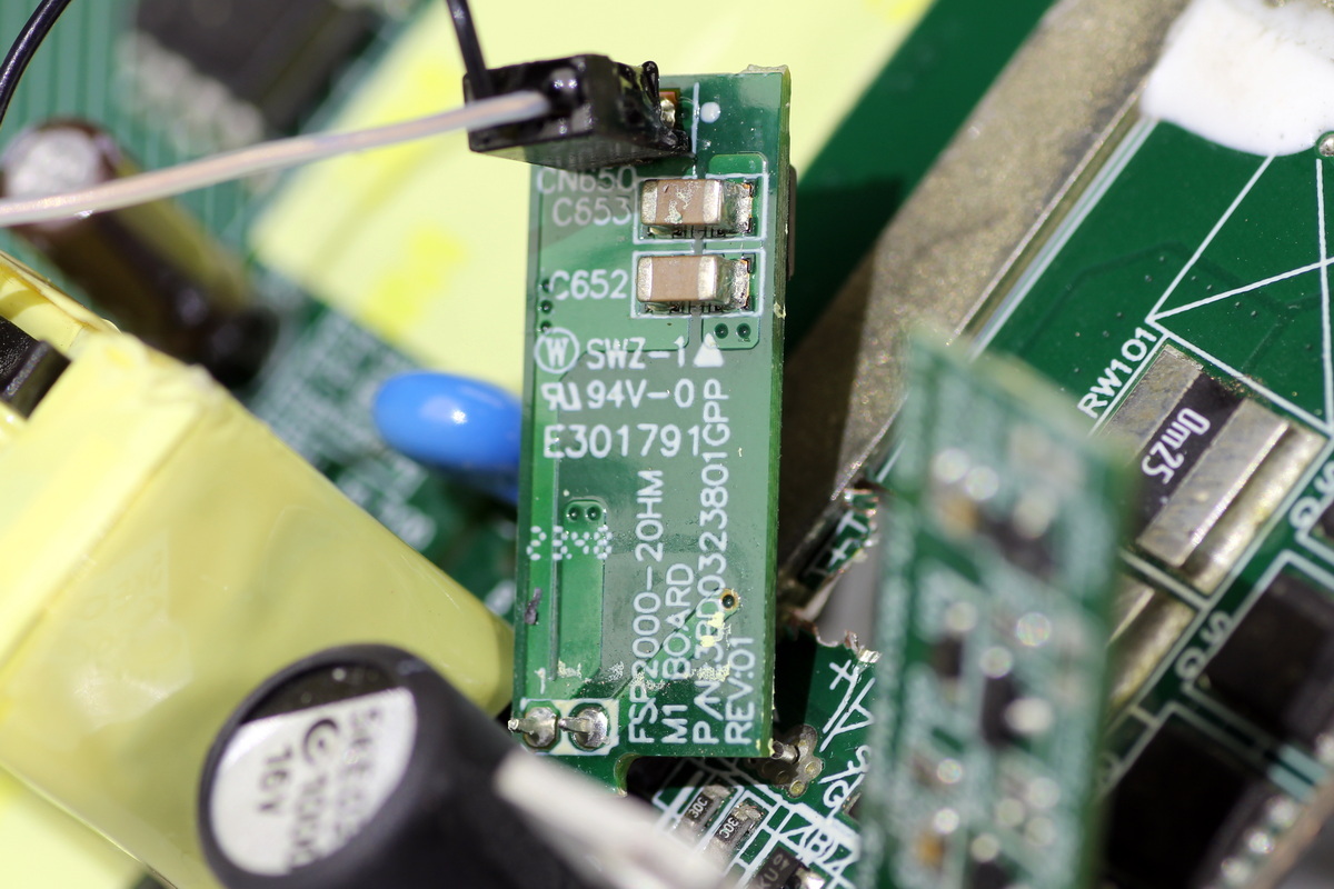
Filter caps are located on the back of the PCB.
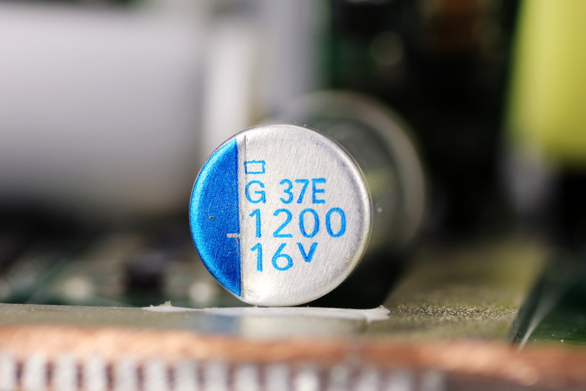
The filter cap comes from NCC and is rated at 1200μF 16V.

The outer side of the control PCB features the PFC controller, phase-shifted full-bridge controller, and operational amplifier.
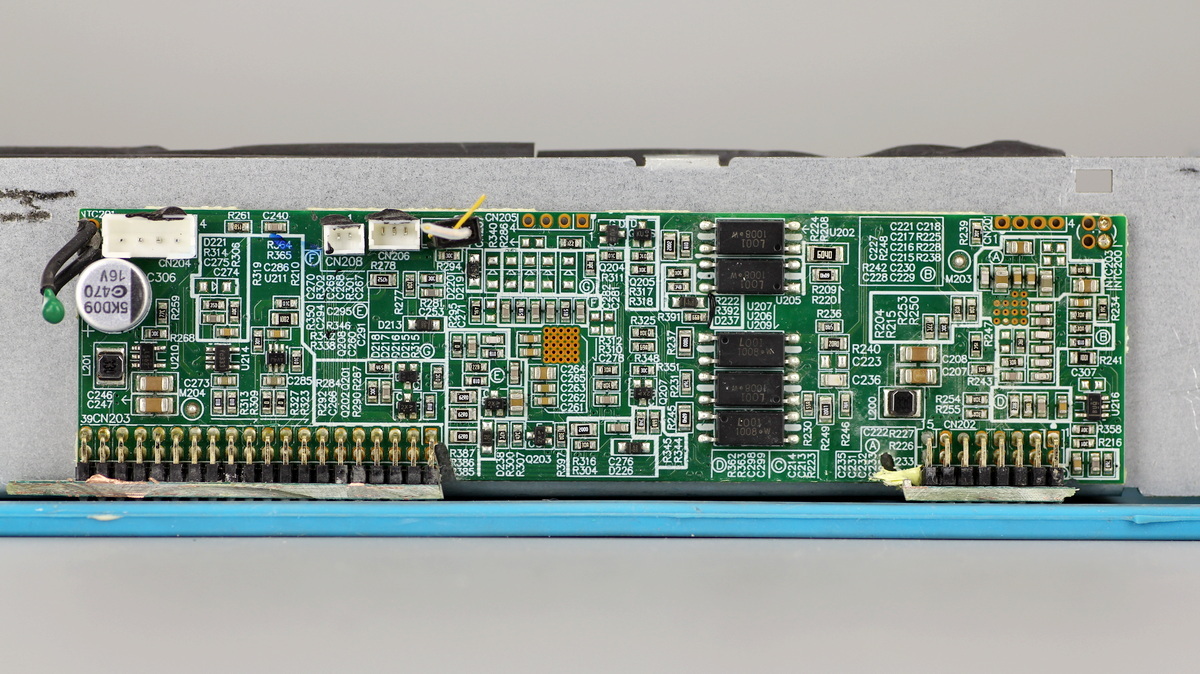
The other side of the PCB features feedback optocouplers, a buck converter, operational amplifier, and filter caps.
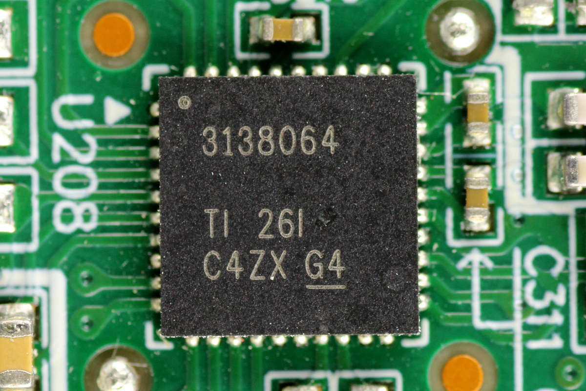
The PFC controller is from TI, model UCD3138064, which is a digital power controller integrating 64kB of Flash memory and supporting SPI and I2C interfaces. It supports phase-shifted full-bridge, single-phase and interleaved PFC, bridgeless PFC, hard-switched full-bridge and half-bridge, half-bridge LLC, and full-bridge LLC applications. It comes in a VQFN40 package.
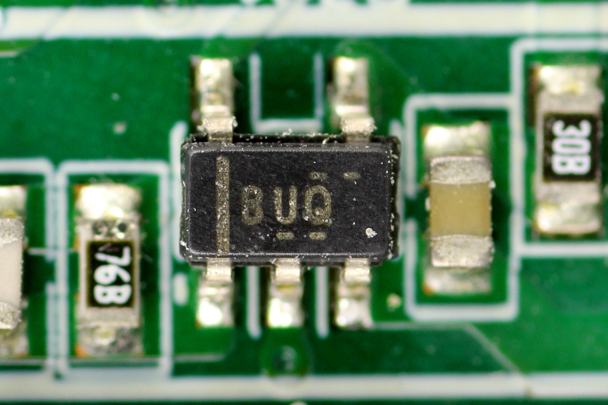
The operational amplifier comes from TI, marked BUQ, model OPA376, which is a precision, low-quiescent-current operational amplifier supporting rail-to-rail input and output, and comes in a SOT-23 package.
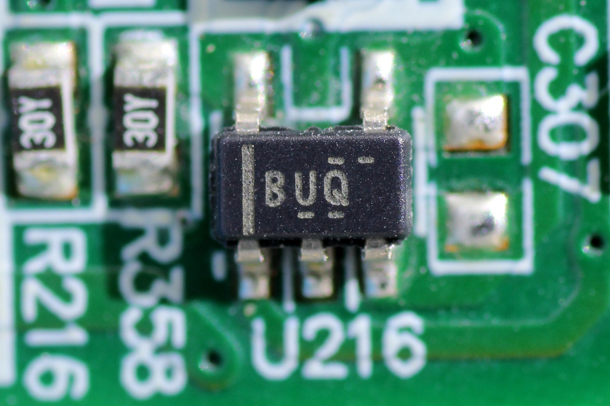
Another one shares the same model.
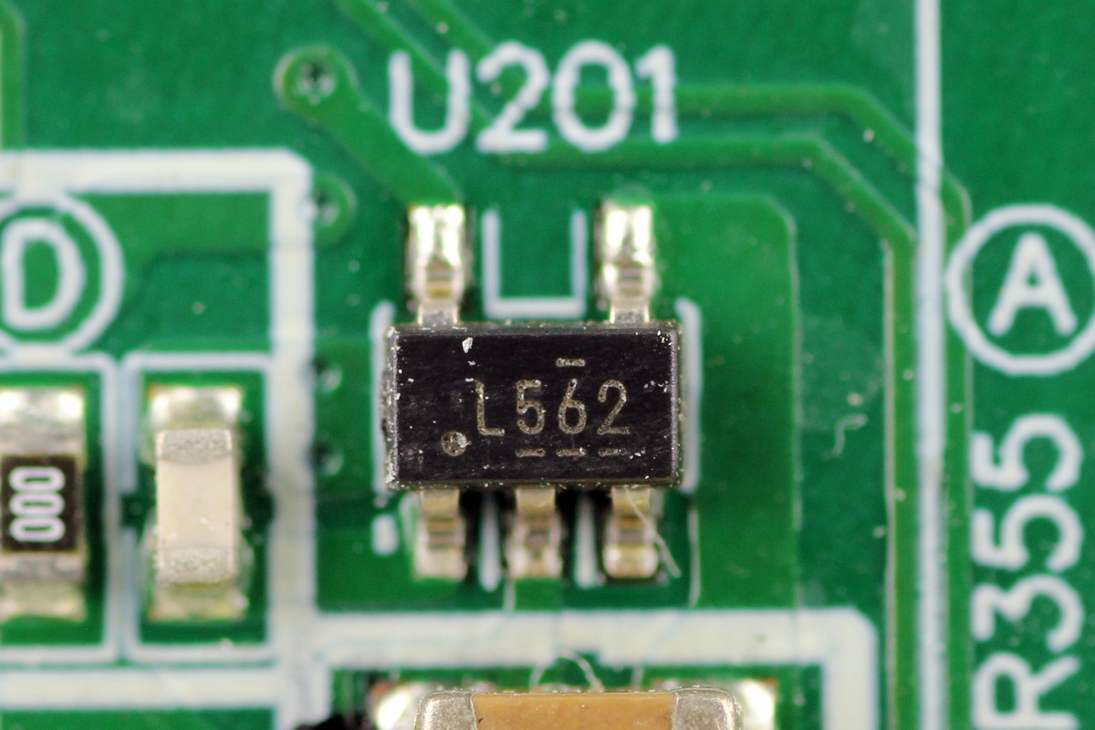
The synchronous buck converter comes from TI, marked L562, model TPS560200, which supports up to 17V input voltage and 500mA output current, integrates the switching MOSFETs, and comes in an SOT-23 package.
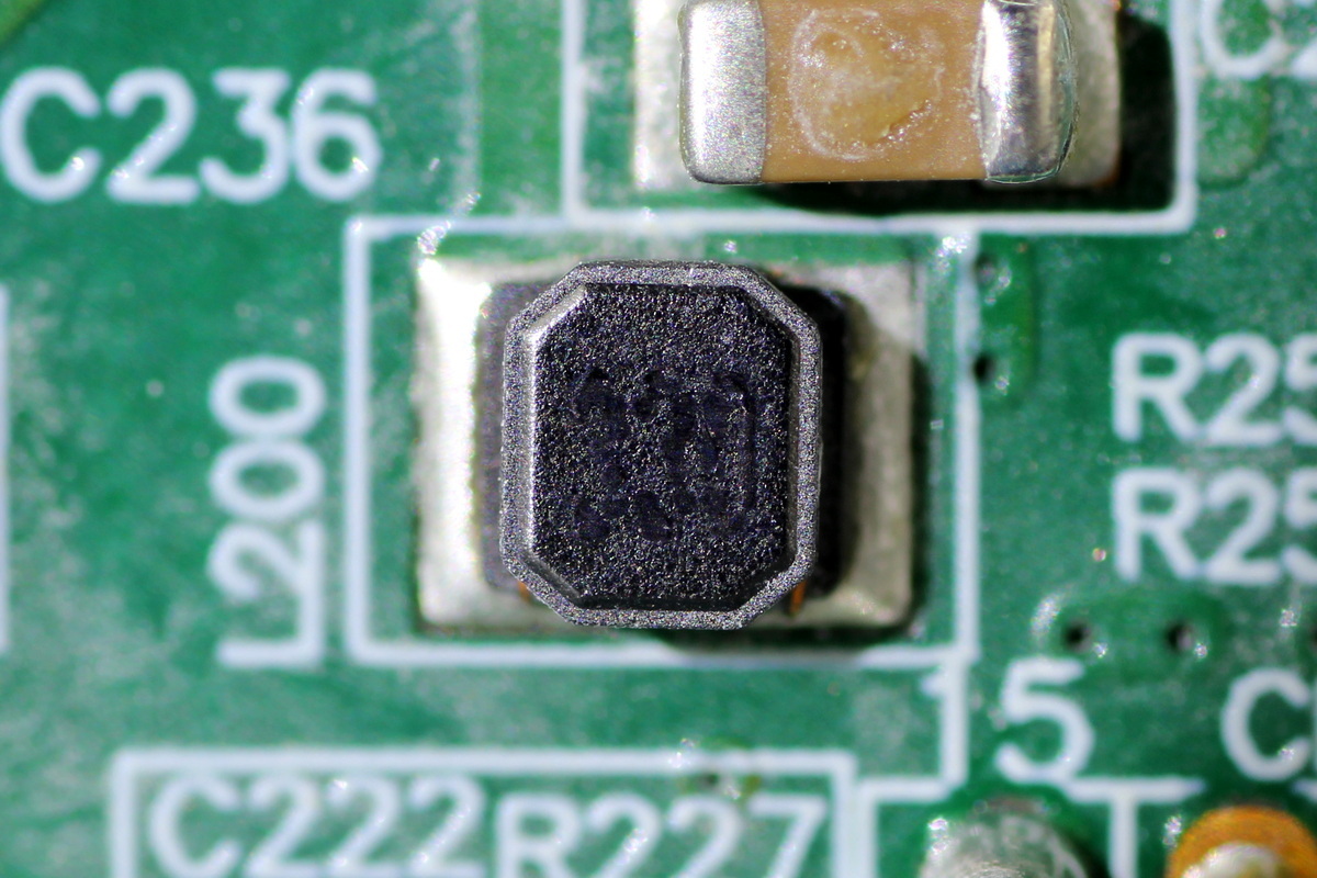
The 33μH buck inductor.
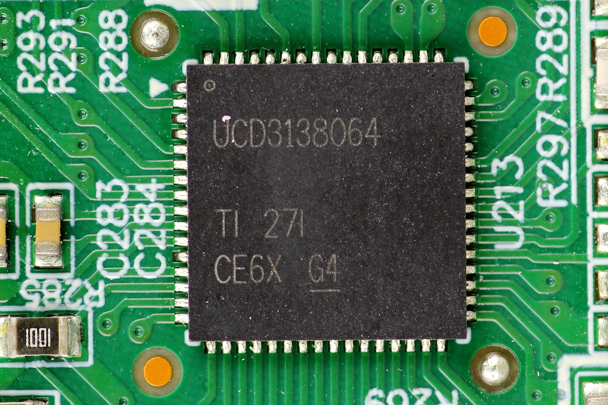
The phase-shifted full-bridge controller comes from TI, model UCD3138064. It is the same model as the PFC controller and comes in a VQFN64 package.
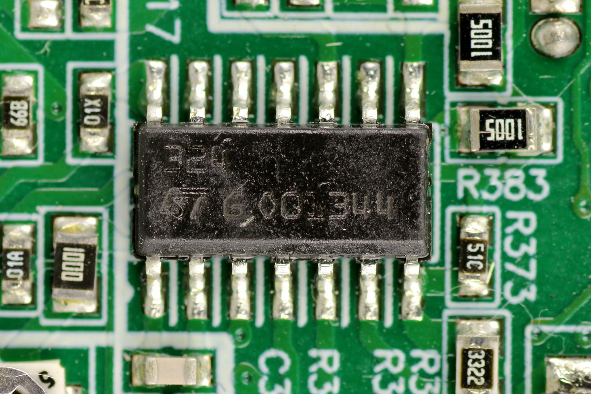
The operational amplifier comes from ST, model LM324, which is a low-power quad operational amplifier with low input bias current, supports a 3–30V supply voltage range, and comes in an SO-14 package.
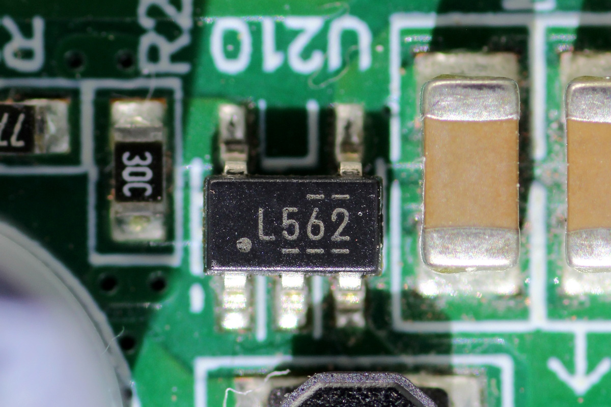
The synchronous buck converter is the TI TPS560200.
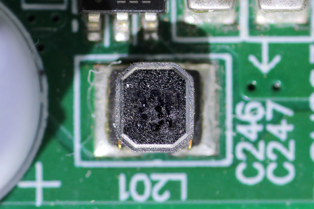
The 33μH buck inductor.
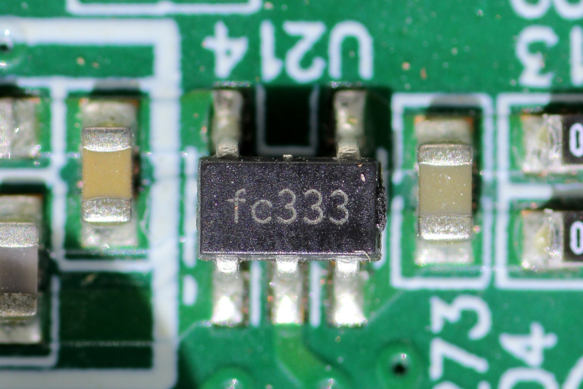
The chip, marked FC333.
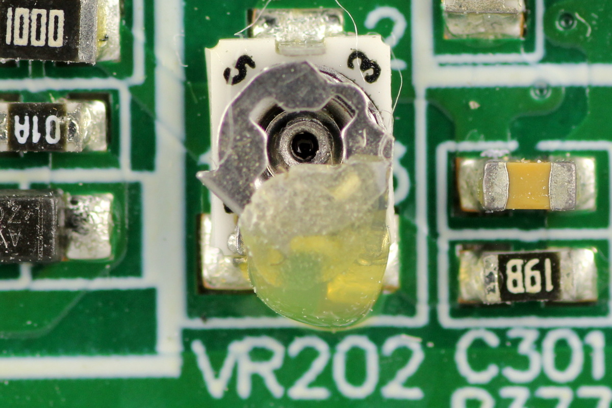
The adjustable resistor is secured with potting compound.
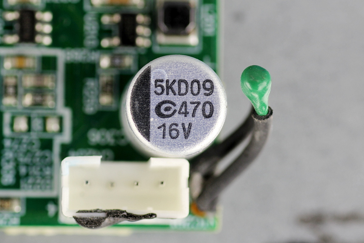
The filter cap comes from APAQ and is rated at 470μF 16V.
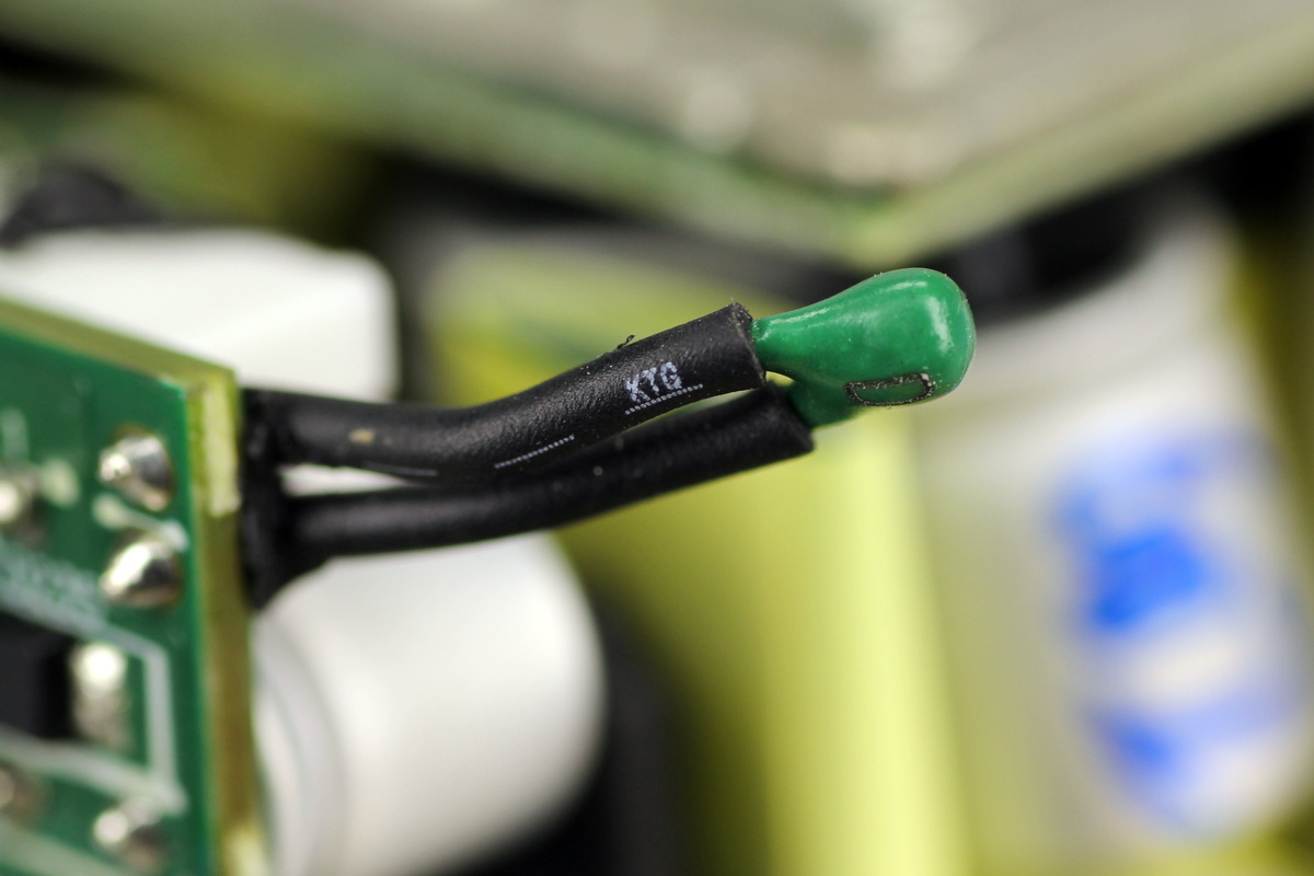
The thermistor leads are covered with heat-shrink tubing for insulation.
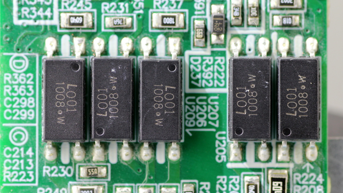
The LITEON LTV1008 optocoupler is used for isolated communication.
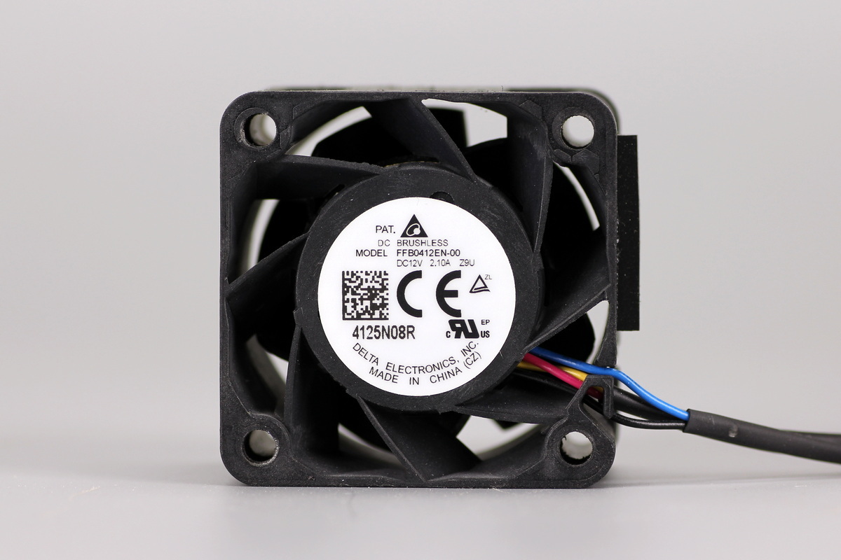
The cooling fan comes from Delta, model FFB0412EN-00, which is rated at 12V 2.1A, made in China, and features stationary guide vanes.
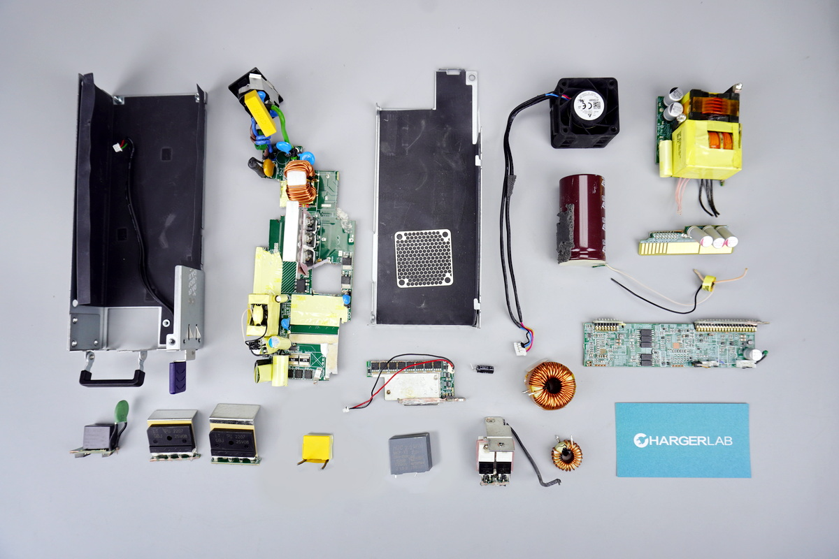
Well, those are all components of the FSP 2000W 80 PLUS Platinum CRPS Power Supply (FSP2000-20FM).
Summary of ChargerLAB
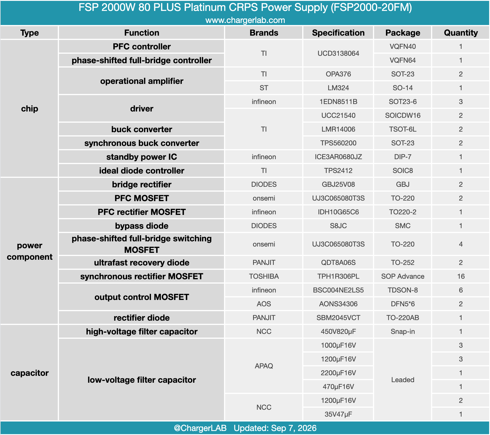
FSP’s FSP2000-20FM server power supply supports universal 100–127V / 200–240V AC inputs alongside 240V DC input compatibility. Delivering a massive 2000W rated power with 80 PLUS Platinum efficiency, it outputs a primary 12V rail at 163.6A and a 12Vsb 3A standby rail. Thermal management is handled by an internal cooling fan pulling air from the rear connector side and exhausting toward the AC inlet.
ChargerLAB's teardown reveals an advanced Active PFC + PSFB + SR topology. Core digital control is managed by two TI UCD3138064 controllers dedicated separately to PFC and PSFB loops. Power conversion relies on onsemi UJ3C065080T3S SiC JFETs for both PFC and bridge MOSFETs, paired with an Infineon IDH10G65C6 SiC diode and TOSHIBA TPH1R306PL SR MOSFETs.
Gate driving is executed via Infineon 1EDN8511B and TI UCC21540 isolated drivers, while standby power relies on an Infineon ICE3AR0680JZ controller. Bulk high-voltage filtering is anchored by NCC electrolytic caps, complemented by APAQ and NCC output caps, showcasing exceptional industrial-grade engineering throughout.
Related Articles:
1. Teardown of the LITEON 3000W Power Supply Unit (PS-2322-HADU-LF)
2. Top 5 AI Power Supply Companies in the First Half of 2026
3. Teardown of the Huntkey AX850P 850W ATX 3.1 80 PLUS Platinum GaN Power Supply