

Introduction
This teardown showcases the Megmeet 1600W SiC CRPS Server Power Supply (Model: MEG-CRPS1600AIP). Designed for versatile deployment, it accommodates 100–120V and 200–240V AC inputs alongside 240V DC input. The unit delivers a main 12V rail pumping out 133A, backed by an auxiliary standby rail outputting 12V at 2.5A.
Built to the industry-standard 185mm CRPS form factor, the topology relies on a PFC stage combined with a half-bridge LLC and synchronous rectification architecture, achieving Platinum-grade conversion efficiency. ChargerLAB now presents a full, hands-on teardown to inspect the internal engineering and component craftsmanship of Megmeet's SiC server power supply.
Product Appearance
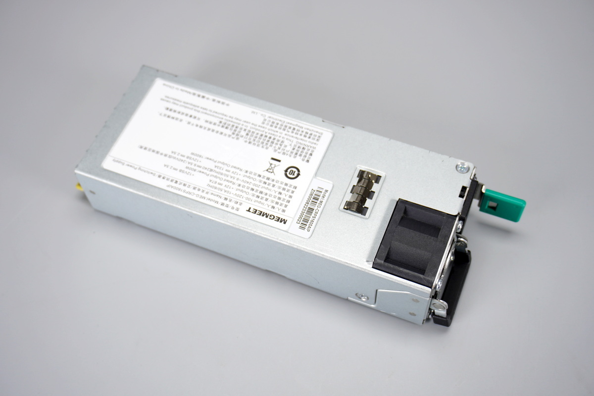
The Megmeet 1600W SiC server power supply features a galvanized steel enclosure.
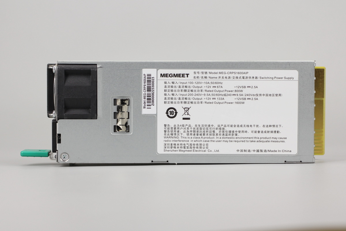
The front of the enclosure features a grounding spring contact and an info label.
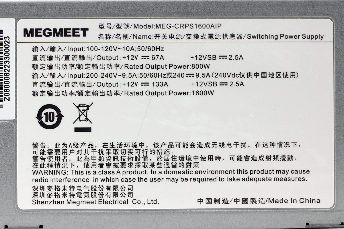
The power supply label:
Model: MEG-CRPS1600AIP
Input: 100-120V~ 10A; 50/60Hz
DC Output: +12V ⎓ 67A, +12VSB ⎓ 2.5A
Input: 200-240V~ 9.5A; 50/60Hz or 240V ⎓ 9.5A
DC Output: +12V ⎓ 133A, +12VSB ⎓ 2.5A
Rated Output Power: 1600W
Shenzhen Megmeet Electrical Co., Ltd.
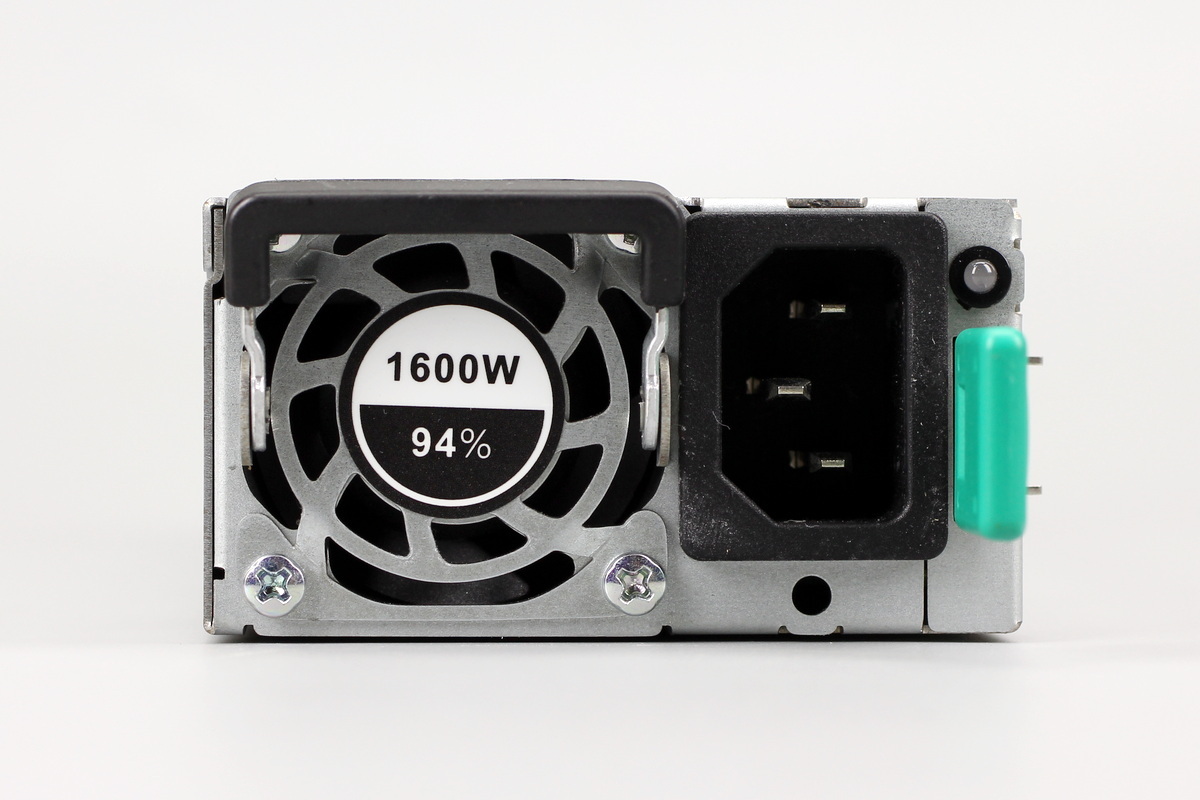
The input end houses a cooling fan, an IEC power inlet, and an LED indicator. A sticker indicates a rated power of 1600W and a conversion efficiency of 94%.
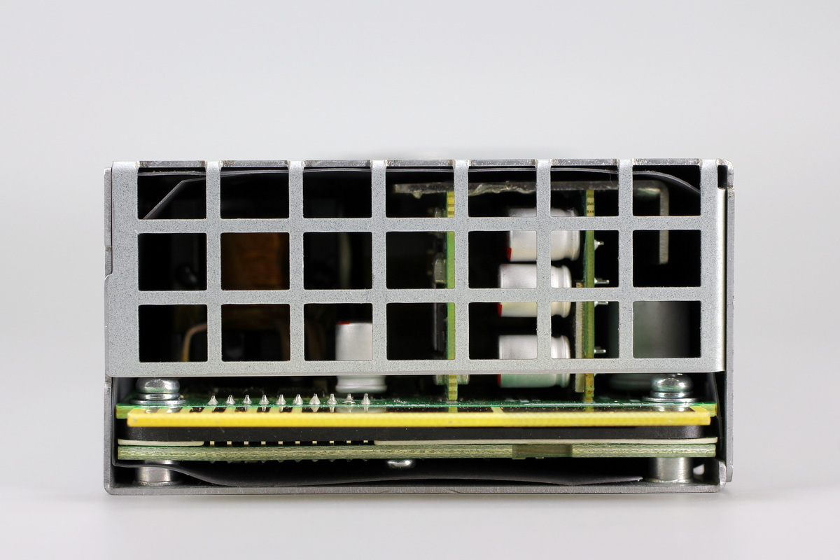
The output end features a ventilation grille and a PCB with gold-finger contacts.
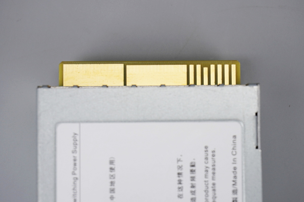
The gold-finger contacts.
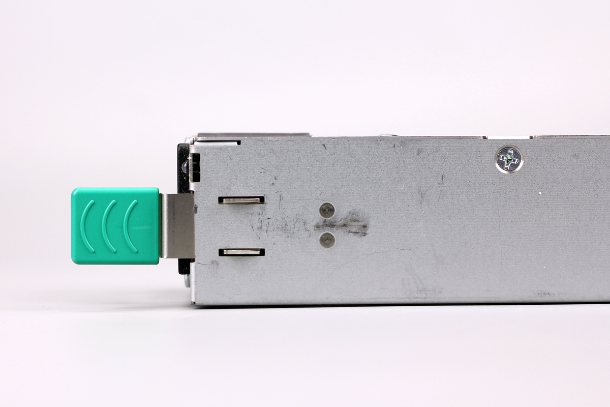
A locking handle is located on the side of the enclosure.
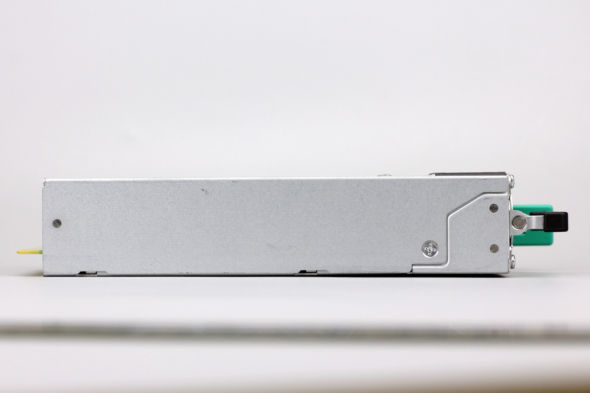
The enclosure is secured with screws.
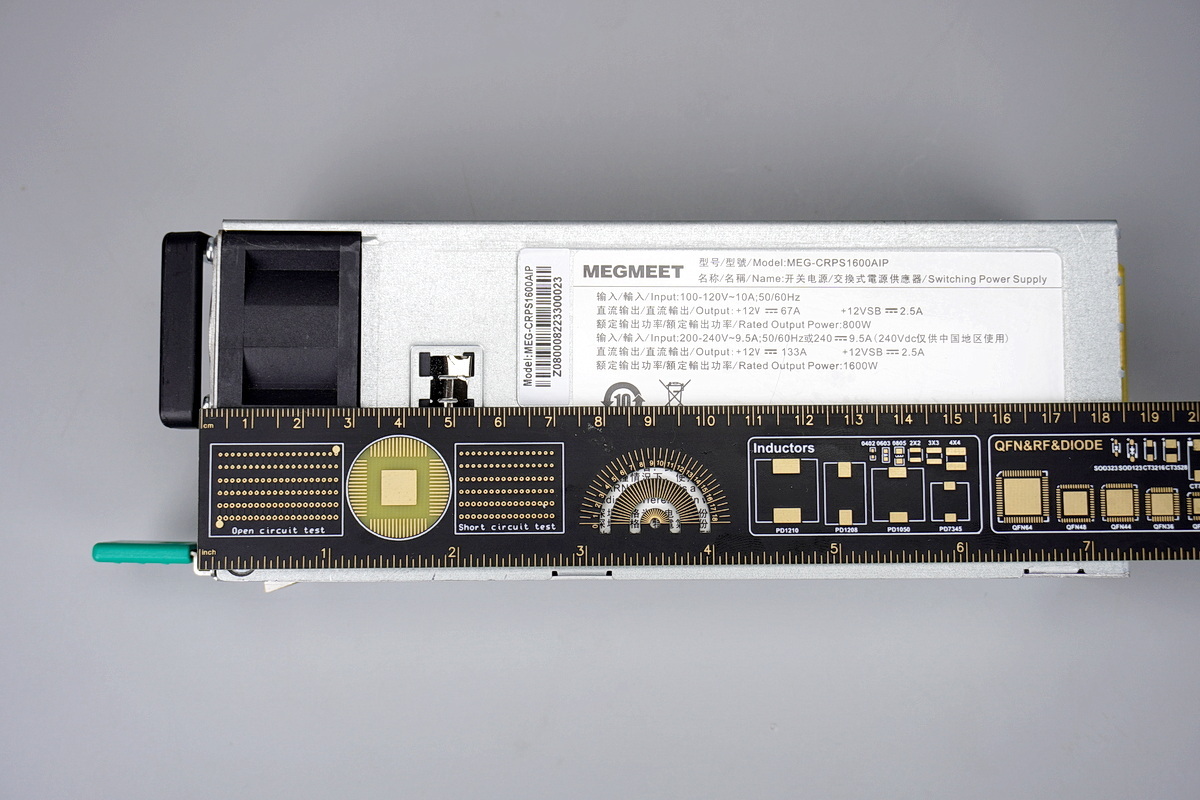
The length of the power supply is about 185mm (7.283 inches).
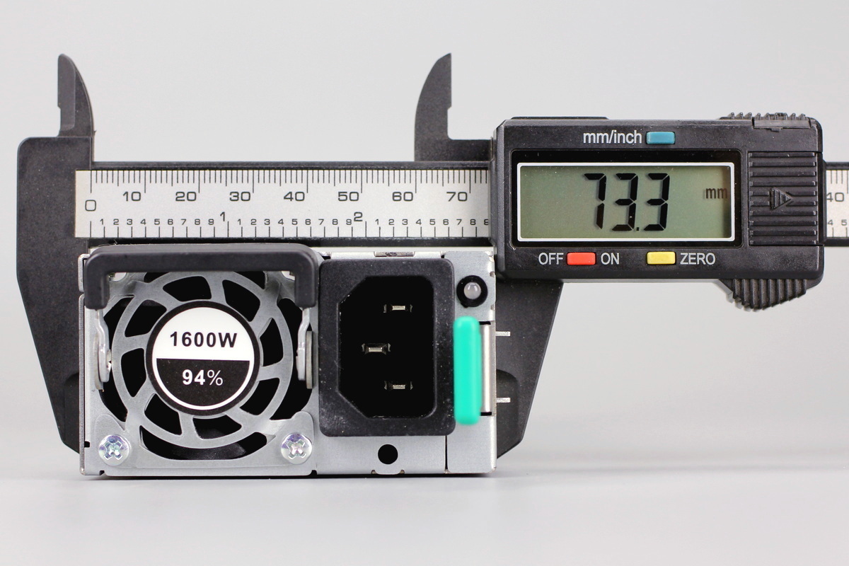
The width of the power supply is about 73.3mm (2.886 inches).
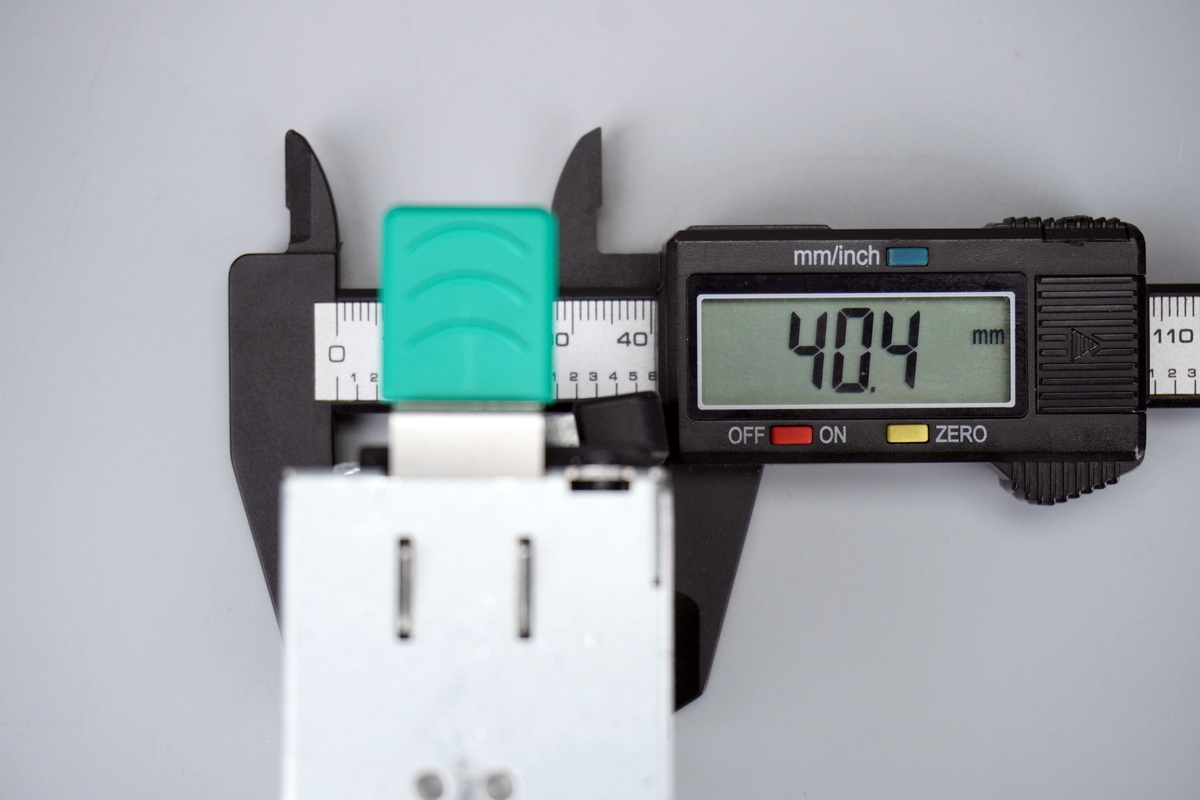
The thickness of the power supply is about 40.4mm (1.591 inches).
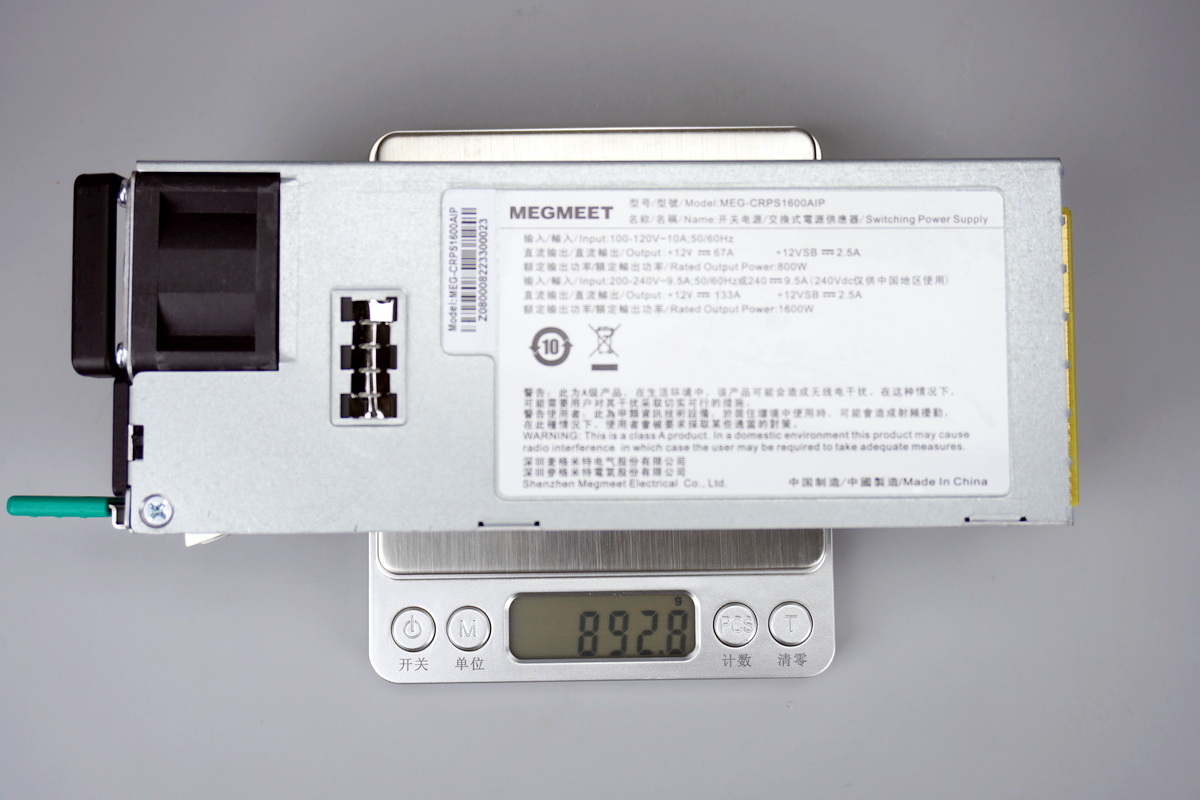
The weight is about 893g (31.500 oz).
Teardown
After examining the exterior of the Megmeet server power supply, we’ll move on to the teardown to see its internal design and components.
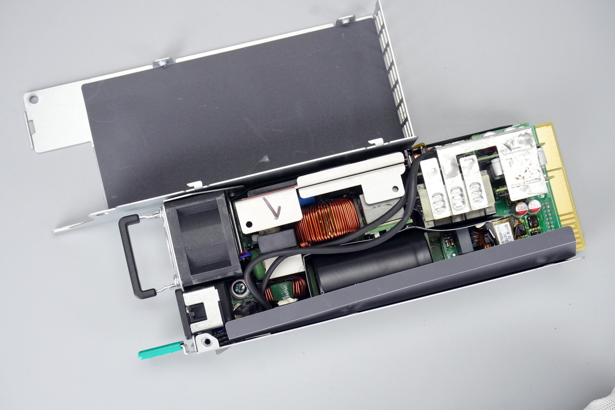
Removing the screws and opening the enclosure shows that a Mylar insulation sheet is attached to the inside of the enclosure.
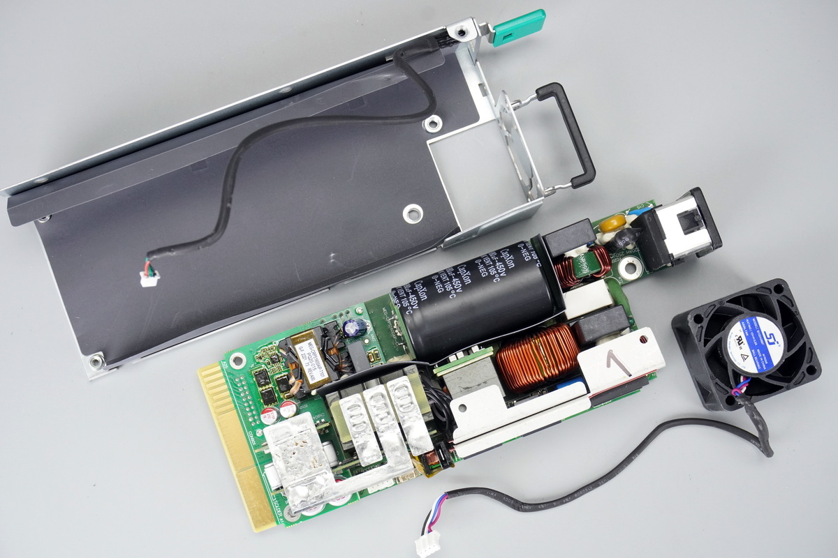
Removing the screws and taking out the PCBA module shows that the Mylar insulation sheet is also installed inside the enclosure for insulation.
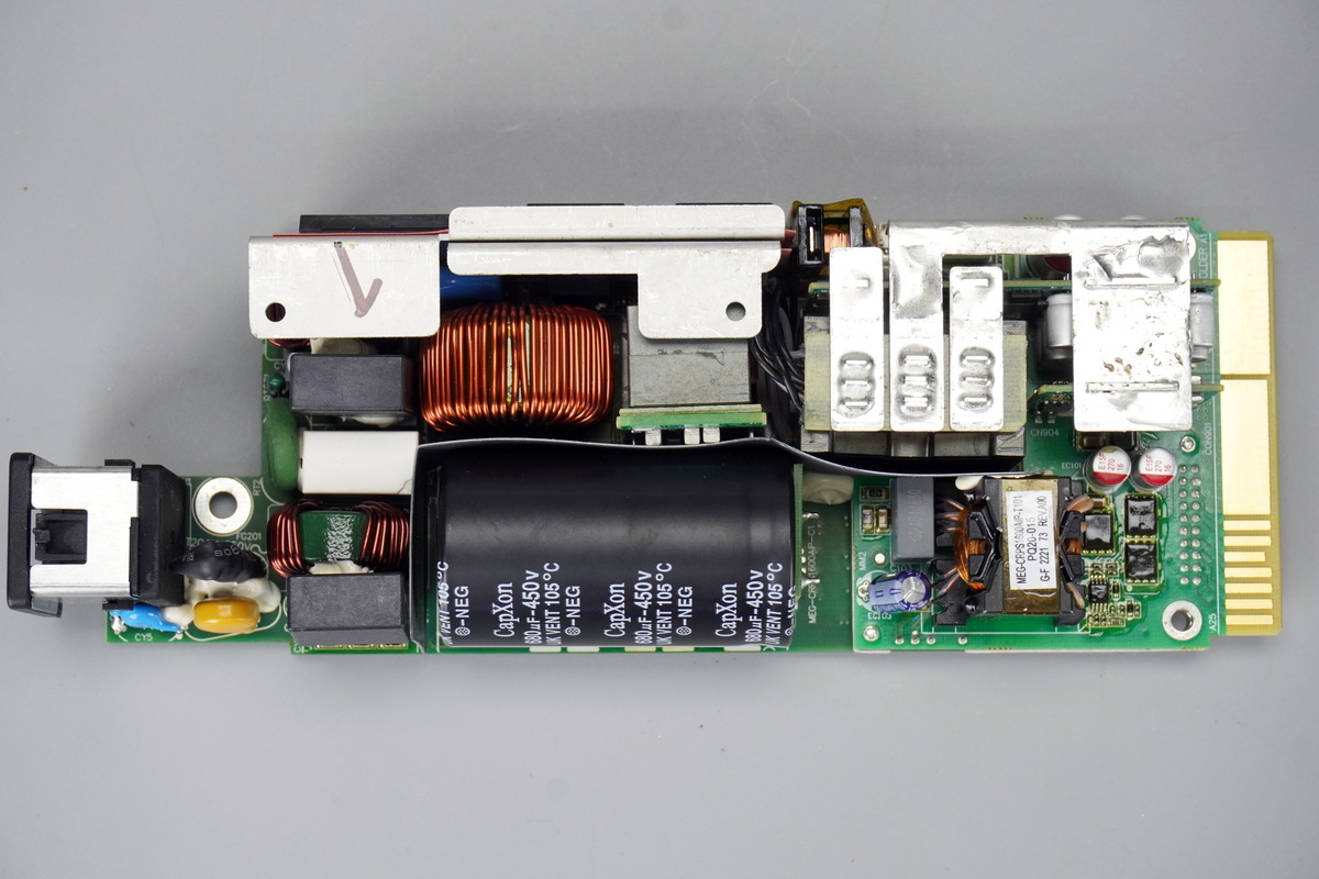
The front of the PCBA module: at the lower left are the power inlet, Y-cap, fuse, varistor, safety X2 cap, and common-mode choke. Above them are the relay, thermistor, and bridge rectifier. The heatsink in the center secures the PFC MOSFET, PFC rectifier, and LLC MOSFETs. Below are the PFC boost choke, resonant inductor, and resonant cap. High-voltage filter caps are located at the bottom, with a Mylar sheet providing insulation.
On the right are the current transformer, LLC transformer, synchronous rectification PCB, and output control PCB. The lower-right section contains the standby power transformer, VBUS MOSFETs, and filter caps. Copper busbars soldered to the transformer connect to the synchronous rectification PCB and output control PCB.
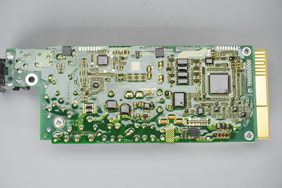
The back of the PCBA module is protected with conformal coating.
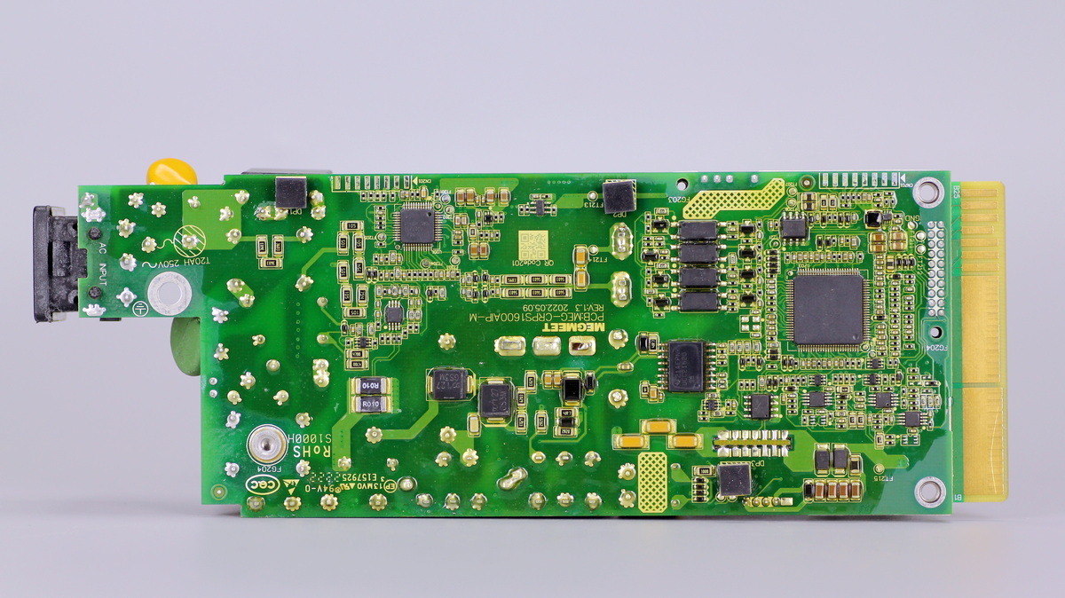
After removing the conformal coating, the PFC controller, operational amplifier, LLC controller, isolated gate driver, memory, and optocoupler can be seen on the back of the PCBA.
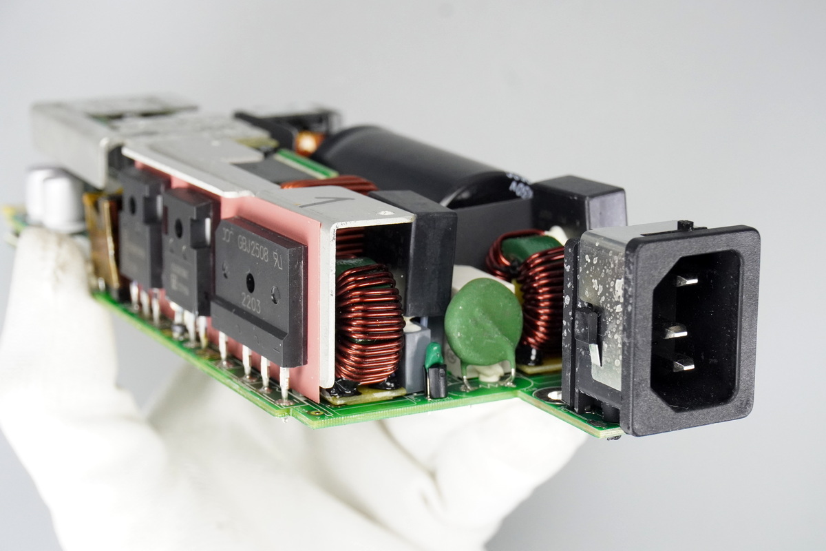
The input end contains a common-mode choke, relay, thermistor, and bridge rectifier.
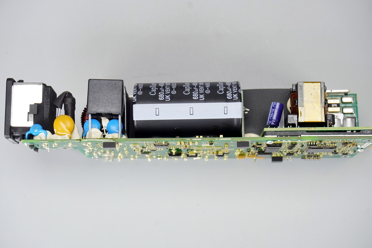
The side contains safety X2 caps, a varistor, high-voltage filter caps, and the standby power transformer.
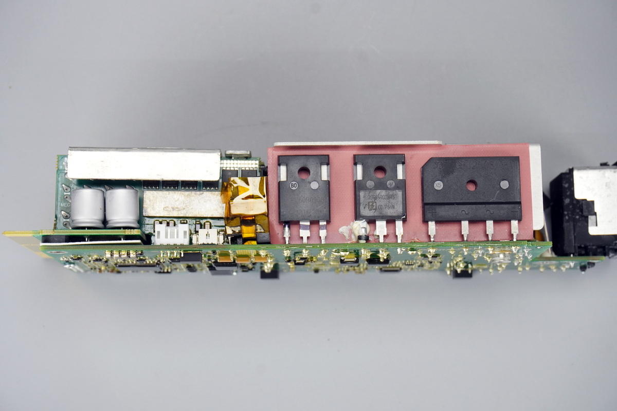
A heatsink on the side of the PCBA secures the bridge rectifier, PFC MOSFET, and LLC MOSFETs. The synchronous rectification PCB and filter caps are located on the left.
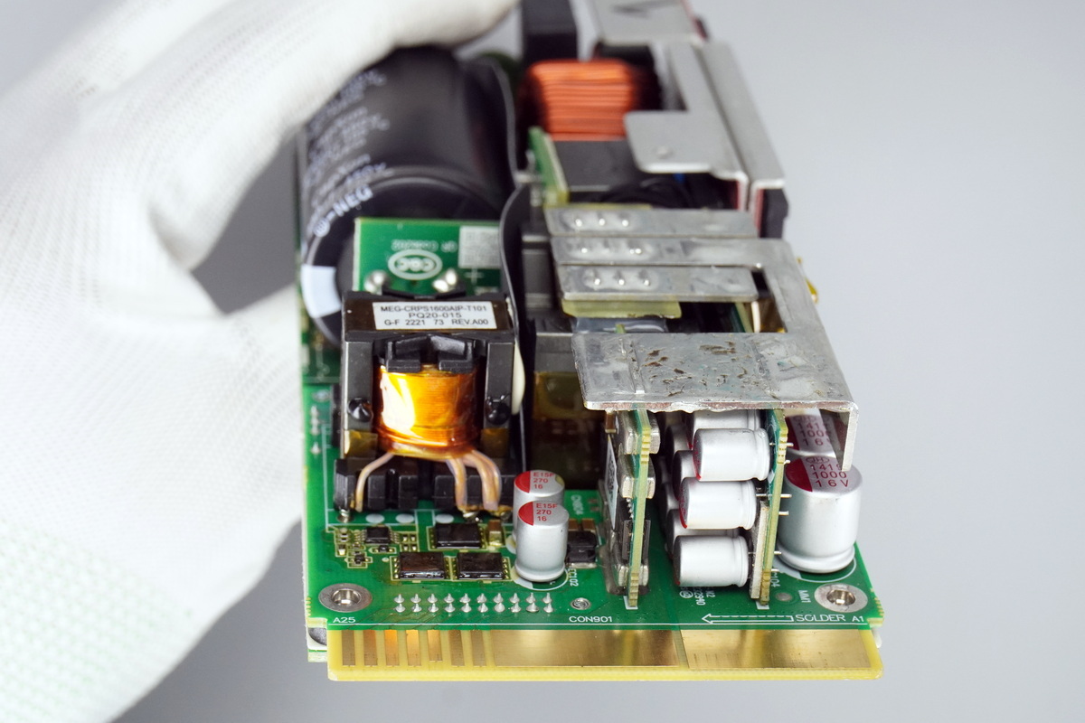
The output end contains switching MOSFETs, filter caps, an ORing PCB, and a synchronous rectification PCB.
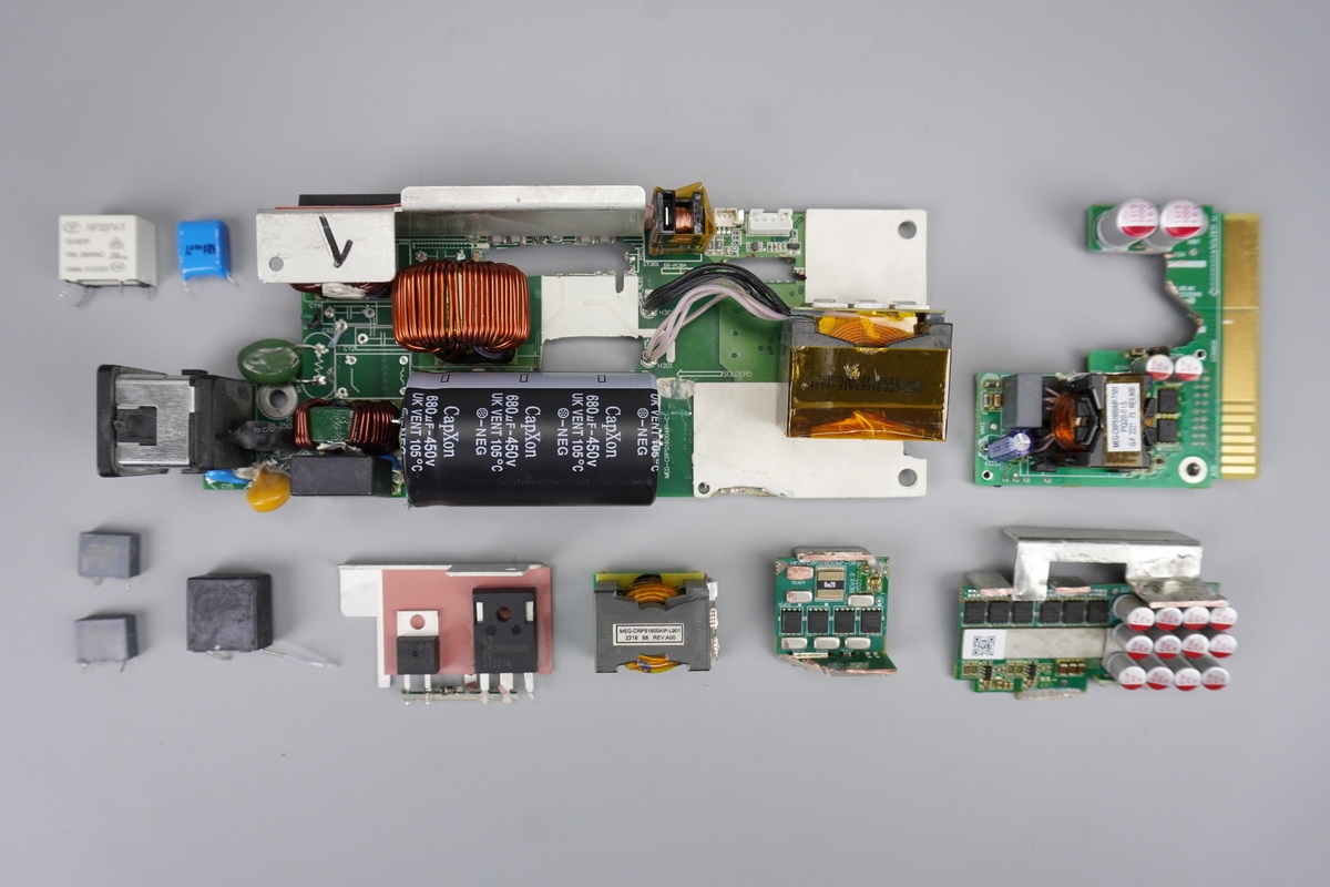
Desolder and remove the film filter cap, then cut the PCB to remove the heatsink, transformer, and PCBA module for further teardown.
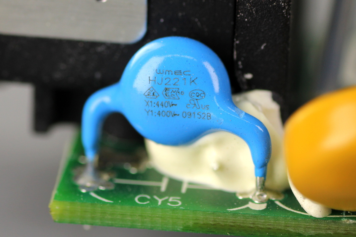
The Y-cap is from WMEC, model HJ221K.
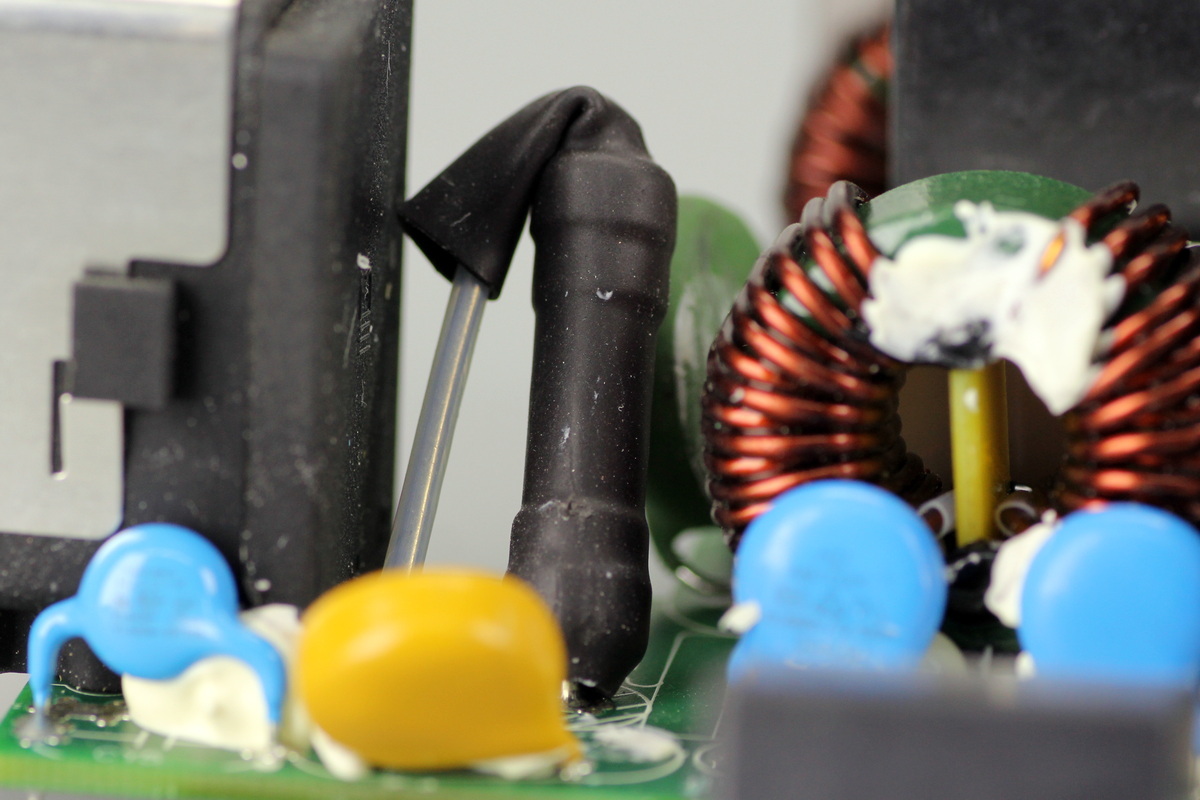
The fuse is insulated with heat-shrink tubing.
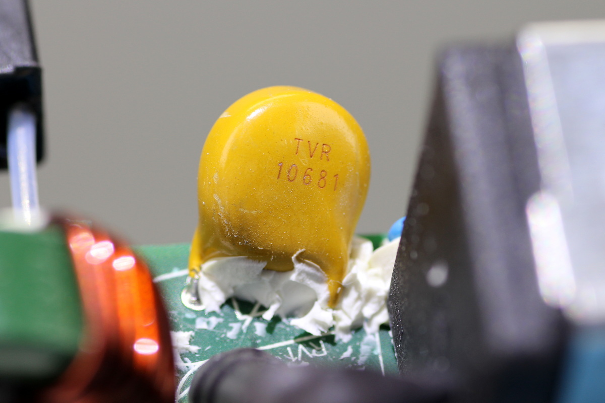
The varistor model is TVR10681 and is used to absorb overvoltage surges.
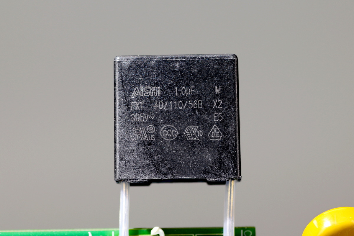
The safety X2 cap is from AiSHi and has a capacitance of 1μF.
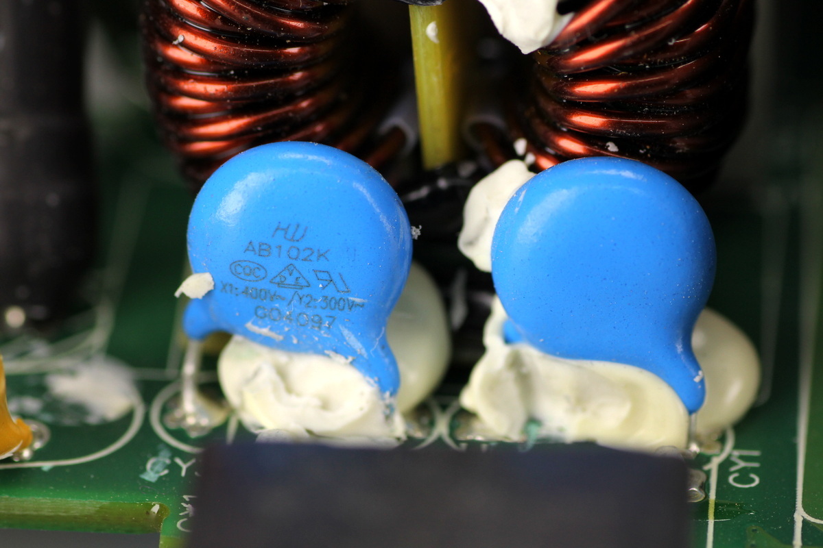
The blue Y-cap has the part number AB102K.
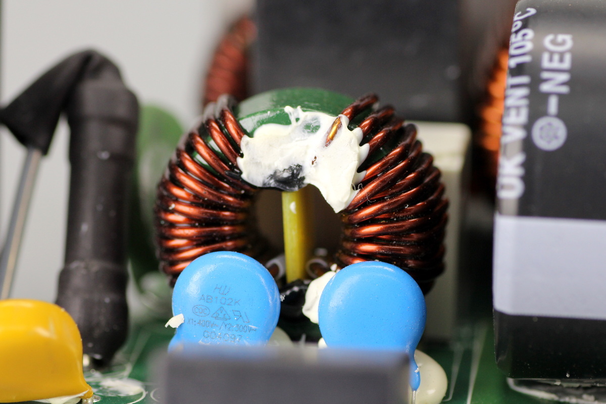
The common-mode choke is wound with enameled wire, with a phenolic insulating board underneath.
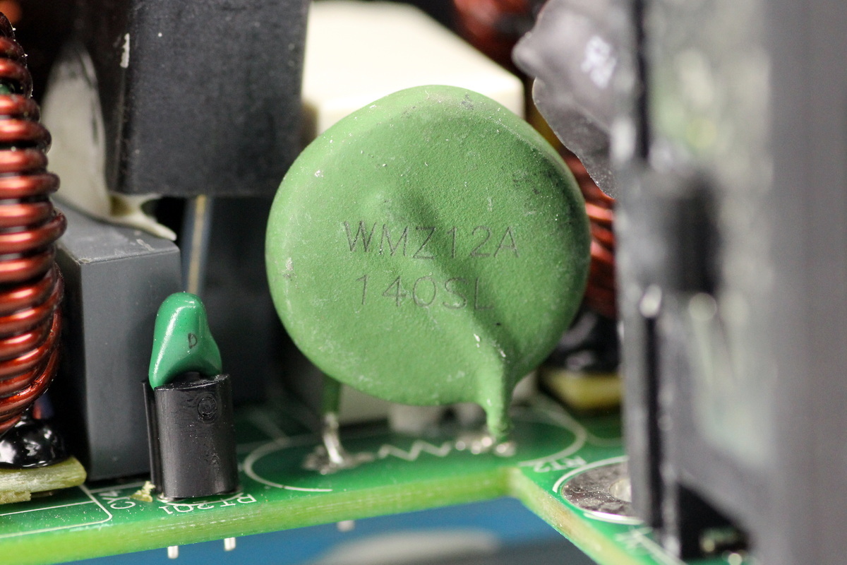
The thermistor, model WMZ12A 140SL.
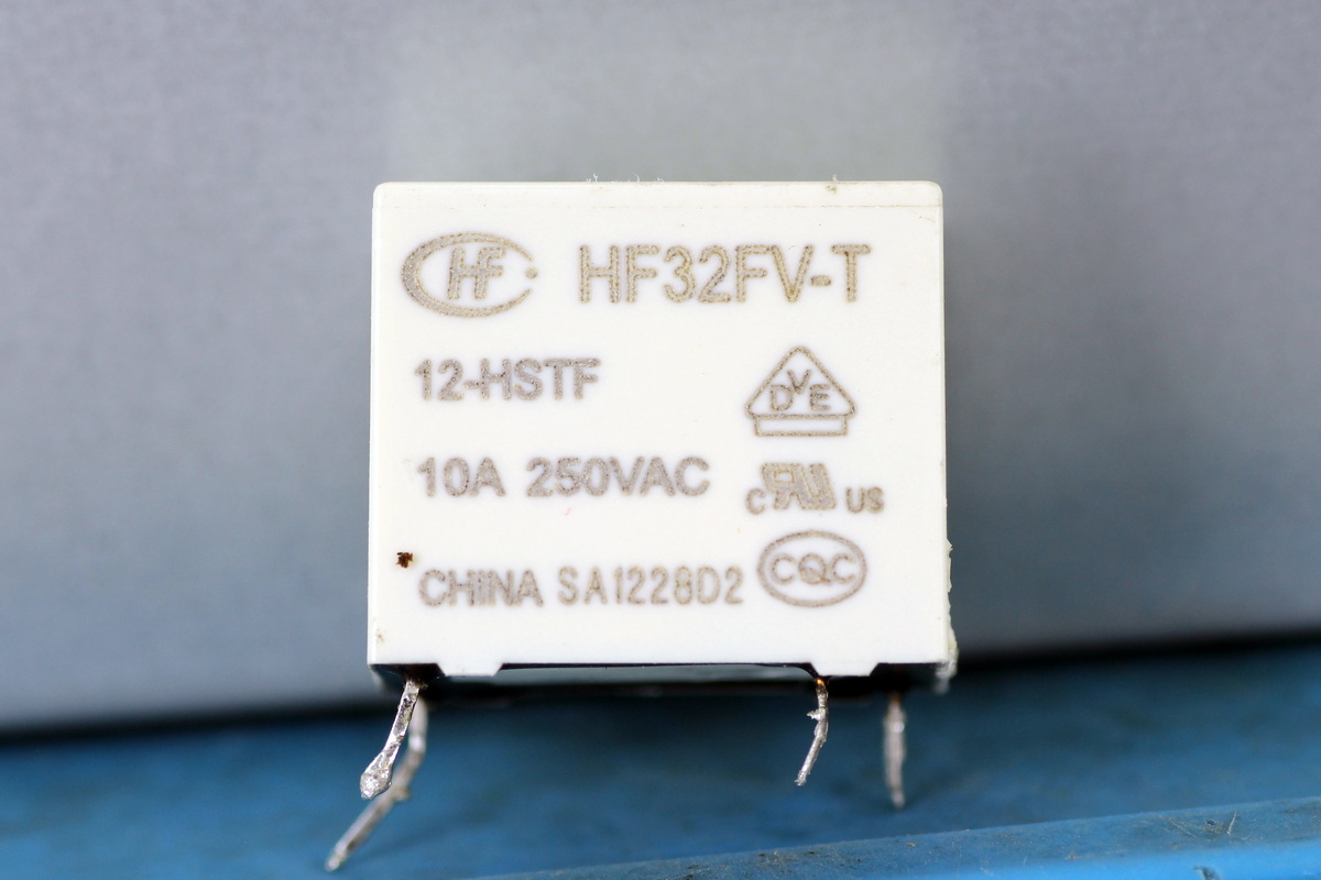
The relay is from HONGFA, model HF32FV-T/12HSTF, which is an ultra-miniature power relay with one normally open contact, a contact rating of 10A, and a coil voltage of 12V.
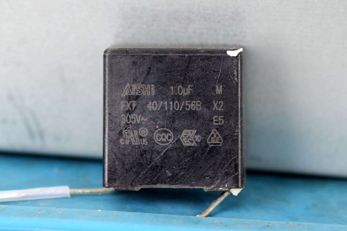
The safety X2 cap has a capacitance of 1μF.
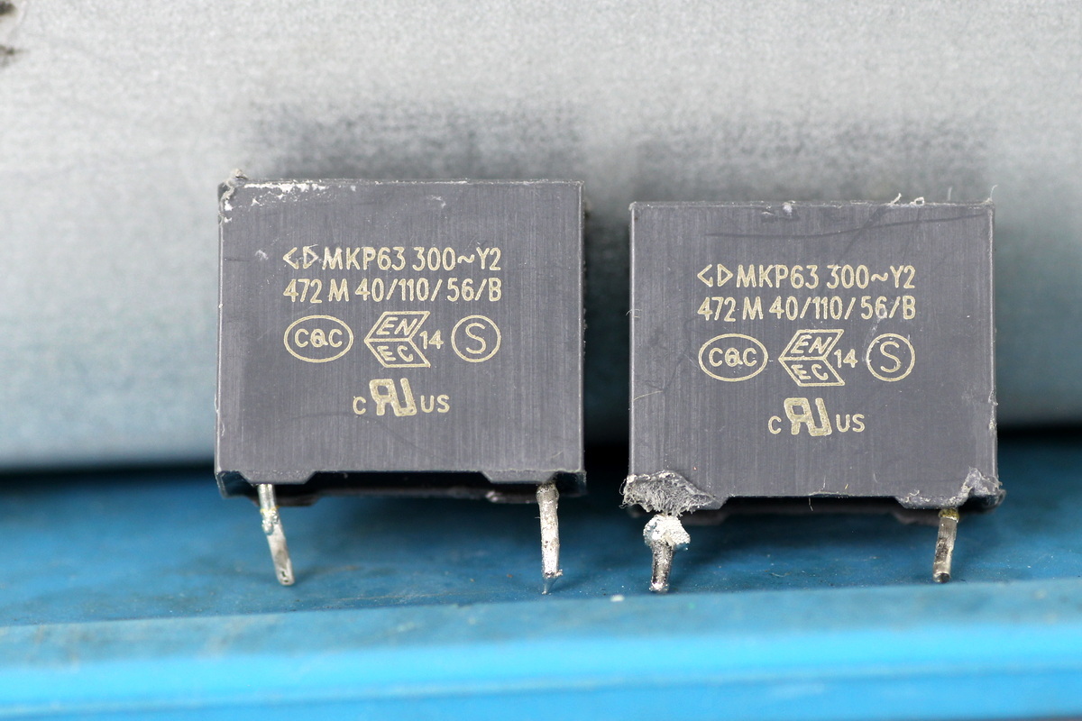
The film Y-cap is from Faratronic and is rated 472M.
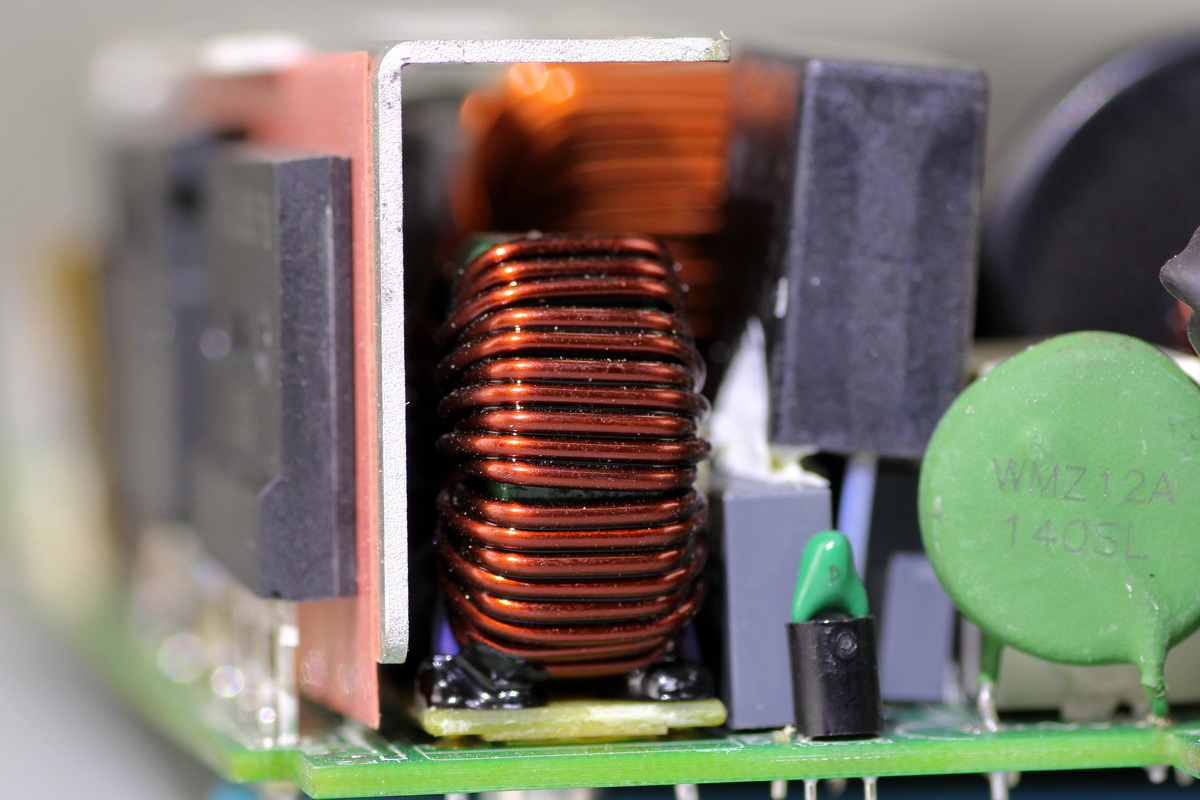
The common-mode choke is wound with enameled wire, with a phenolic insulating board underneath.
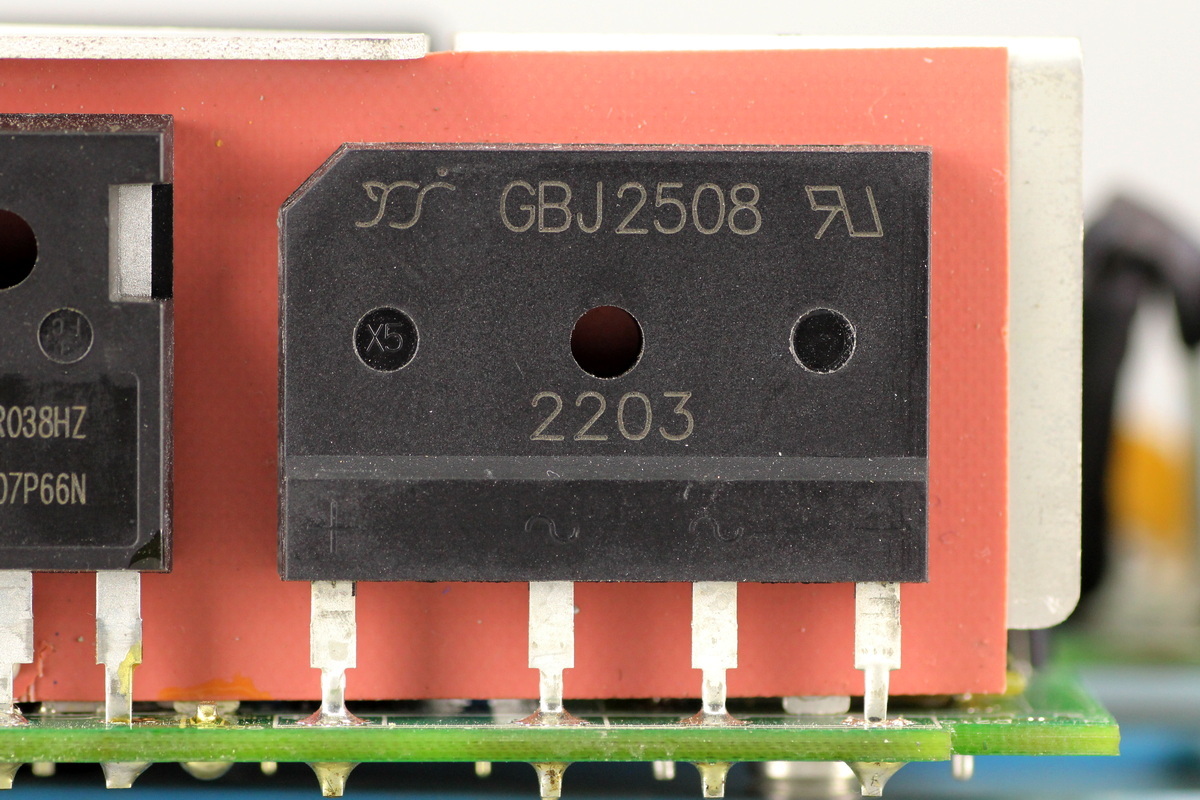
The bridge rectifier is from YJ, model GBJ2508, rated at 800V 25A and housed in a 6KBJ package.
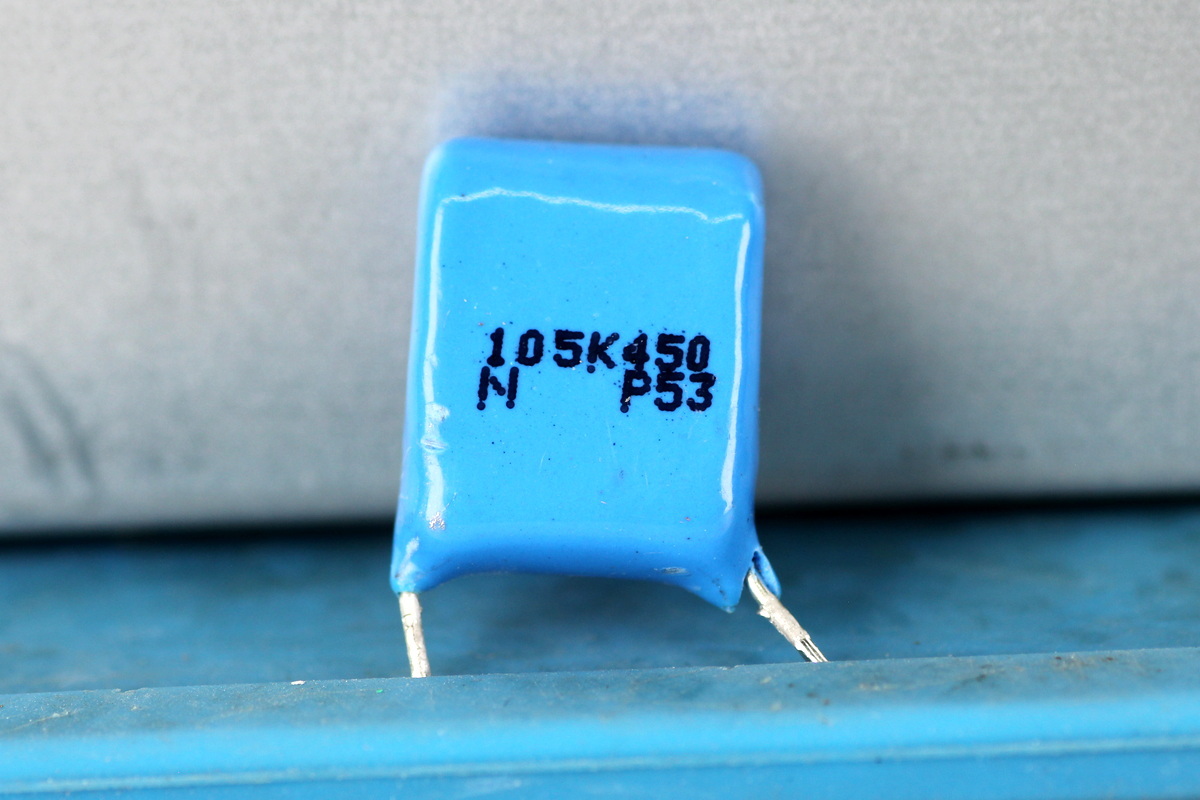
The film filter cap is rated at 1μF 450V.
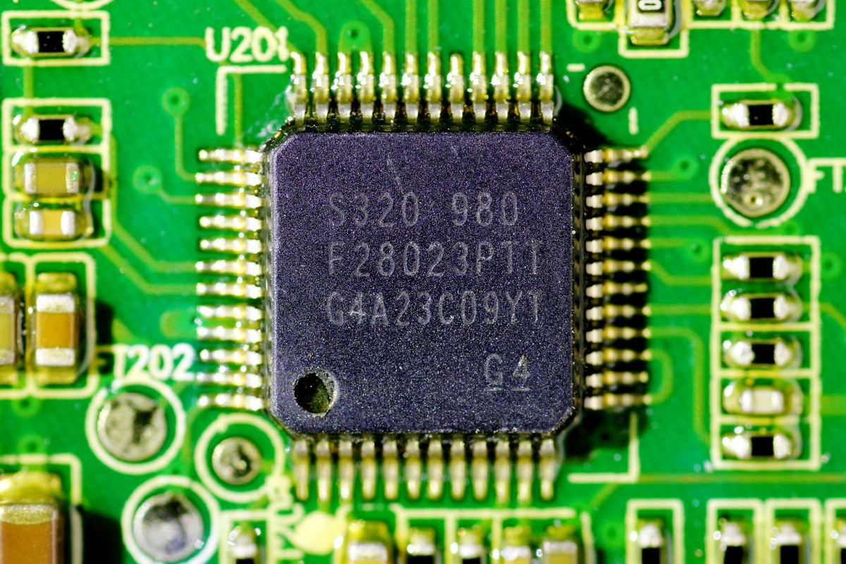
The PFC controller is from TI, model TMS320F28023, a 32-bit microcontroller from the C2000 series. It integrates a 32-bit CPU running at up to 50MHz, along with 32KB Flash and 6KB SARAM. It supports a single 3.3V supply, integrates a 12-bit ADC, and comes in an LQFP48 package.
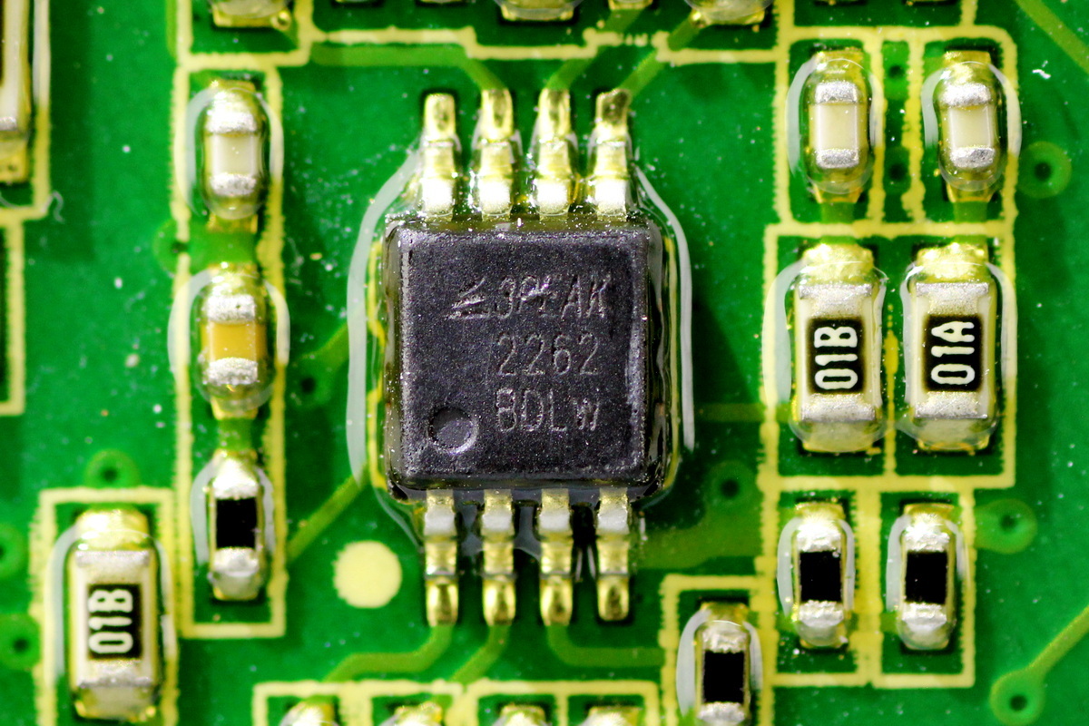
The operational amplifier is from 3PEAK, model TP2262. It supports operation up to 36V and features low offset, low power consumption, and stable high-frequency response. It comes in an MSOP8 package.
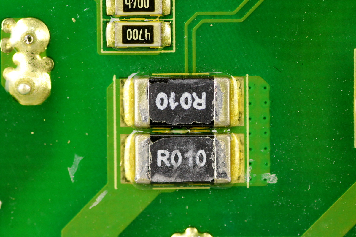
Two 10mΩ current-sense resistors are used to monitor the current through the PFC MOSFET.
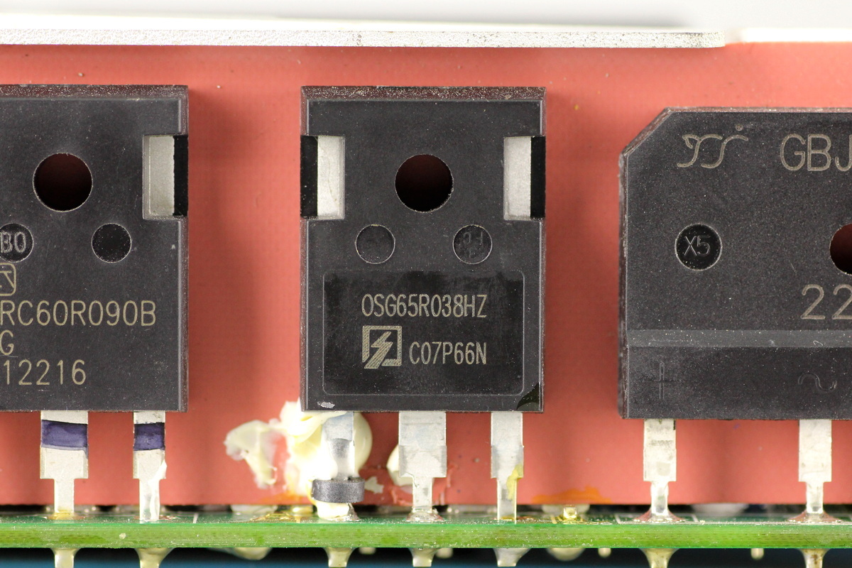
The PFC MOSFET is from Oriental, model OSG65R038HZF, NMOS, 700V and 38mΩ, and comes in a TO-247 package.
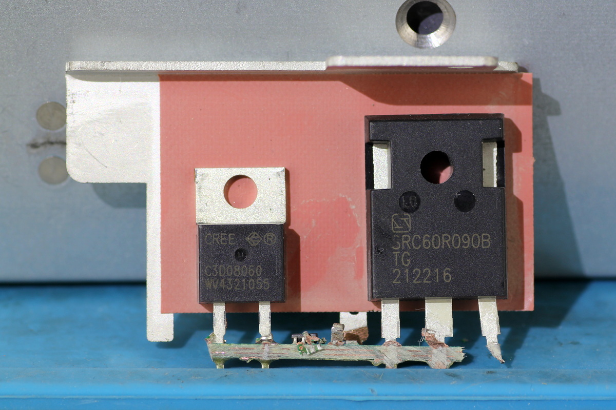
The heatsink secures the PFC rectifier MOSFET and the LLC MOSFET.
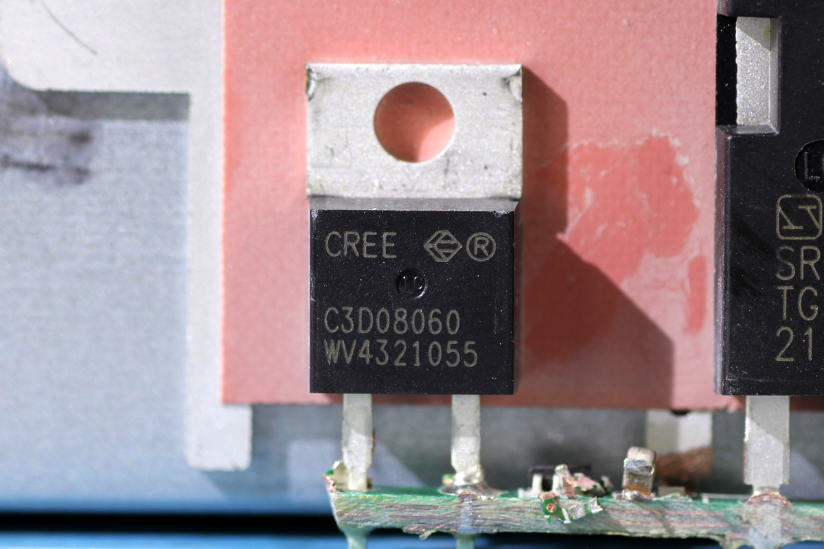
The PFC rectifier MOSFET is from CREE, model C3D08060A, a SiC Schottky diode rated at 600V 8A and housed in a TO-220-2 package.
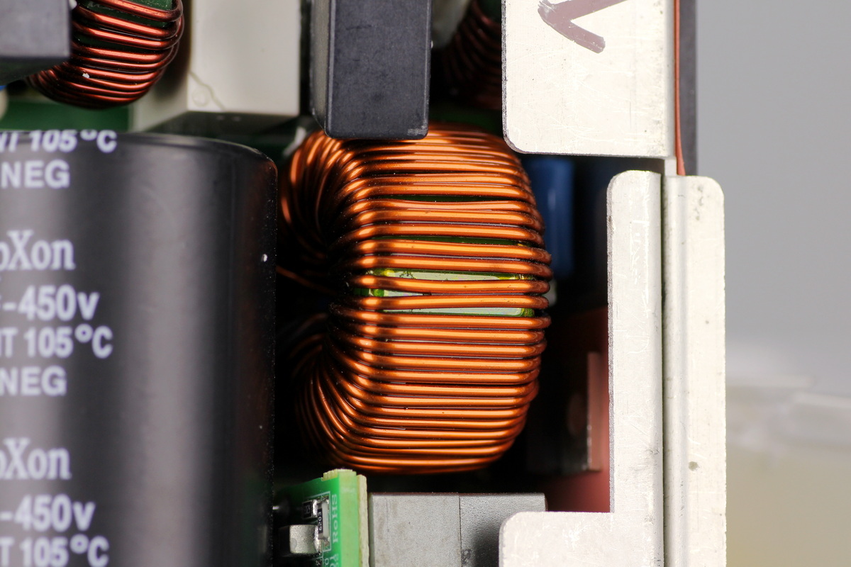
The PFC boost choke is wound on a toroidal core.
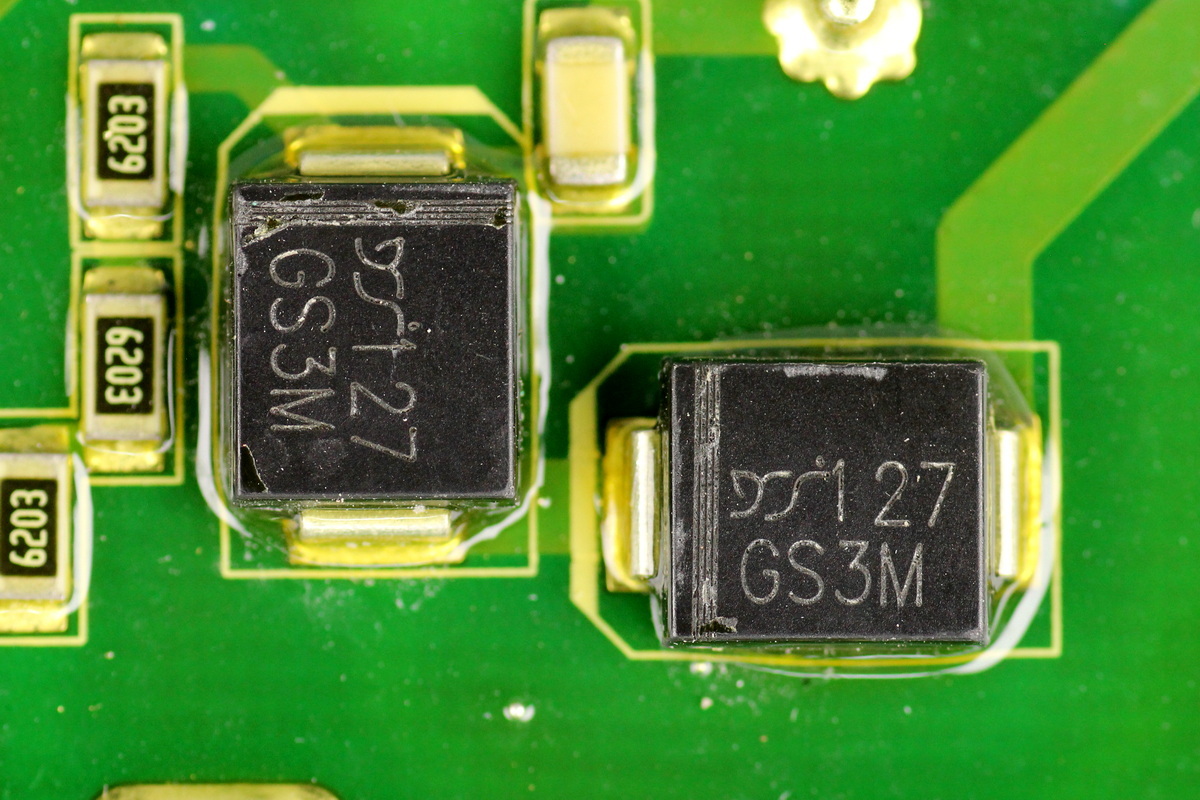
The PFC bypass diodes are from YJ, model GS3M, rated at 1000V 3A in SMC packages. Two are connected in series.
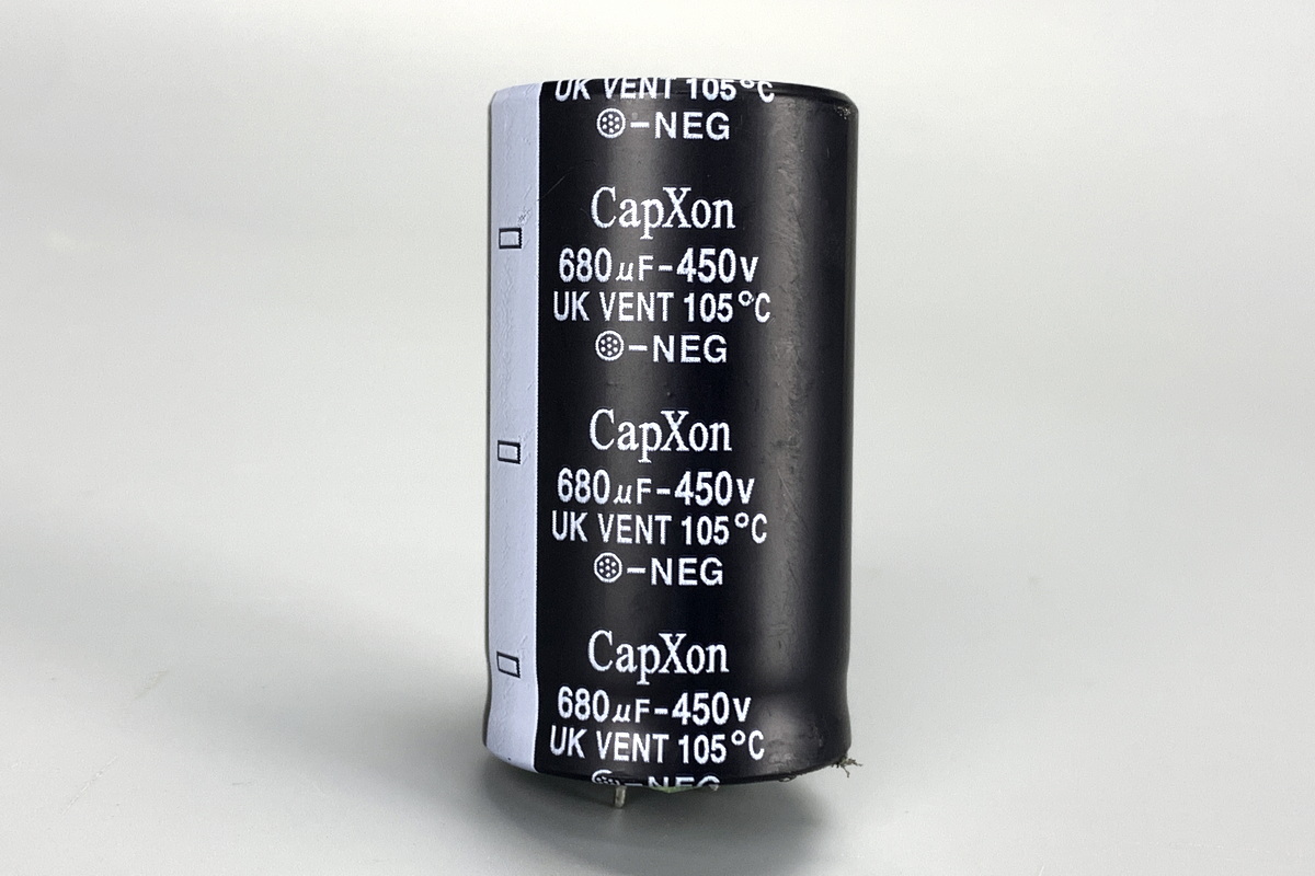
The high-voltage filter cap is from CapXon. It is a UK-series long-life electrolytic cap rated at 680μF 450V.
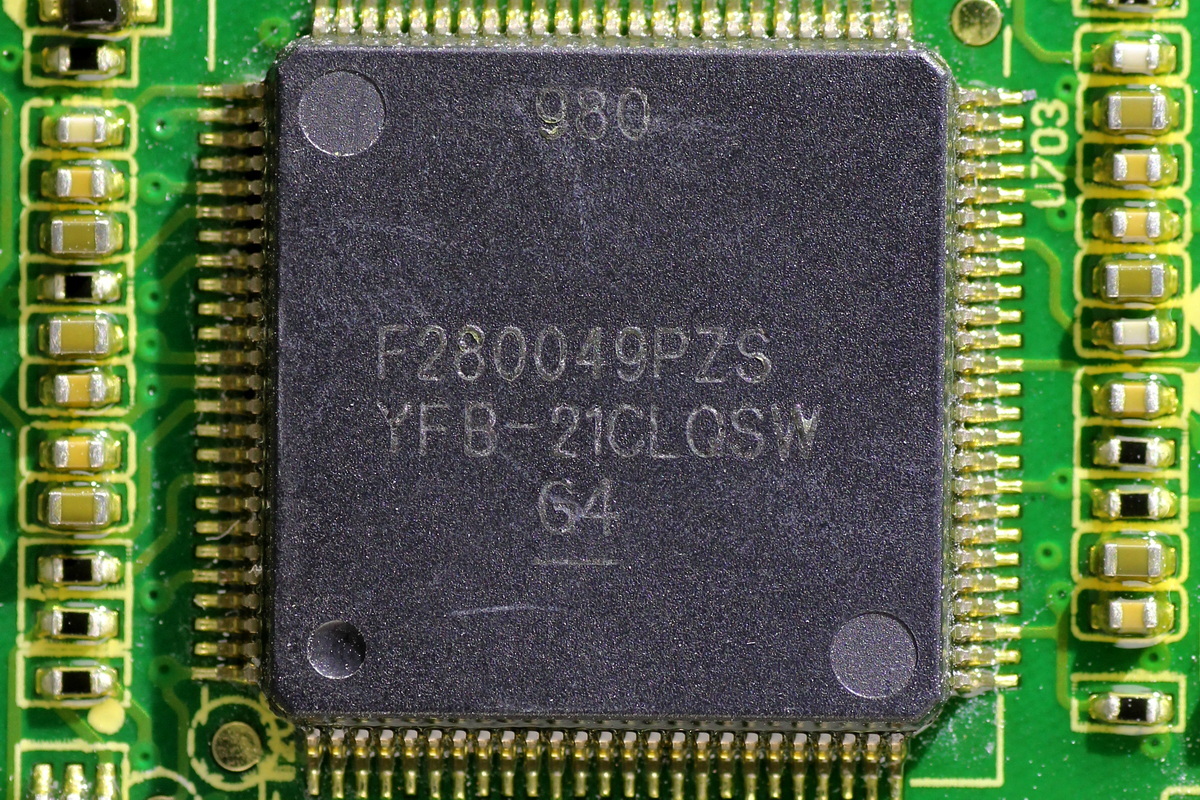
The real-time microcontroller is from TI, model TMS320F280049PZS, used for LLC control and communication. It integrates a C28x CPU and CLA, along with a single-precision FPU, and operates at up to 100MHz. The chip integrates 256KB Flash and 100KB SRAM, along with a 12-bit ADC, PMBus and I2C interfaces, and 16 ePWM channels. It comes in an LQFP100 package.

The memory is from GIANTEC, marked 402A-2GLI, model GT24C02A. It has a capacity of 2KB, supports an operating voltage of 1.7-5.5V, and comes in an SOIC8 package.
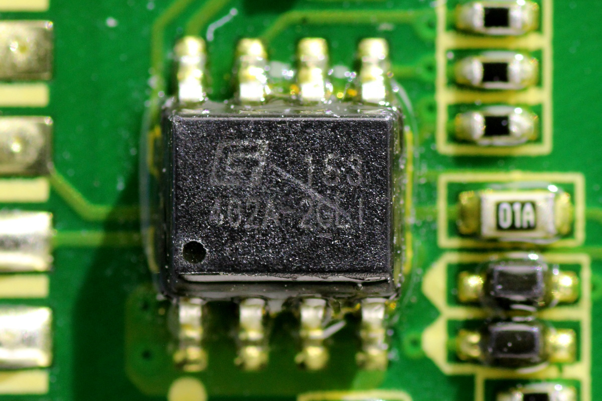
The other one shares the same model.
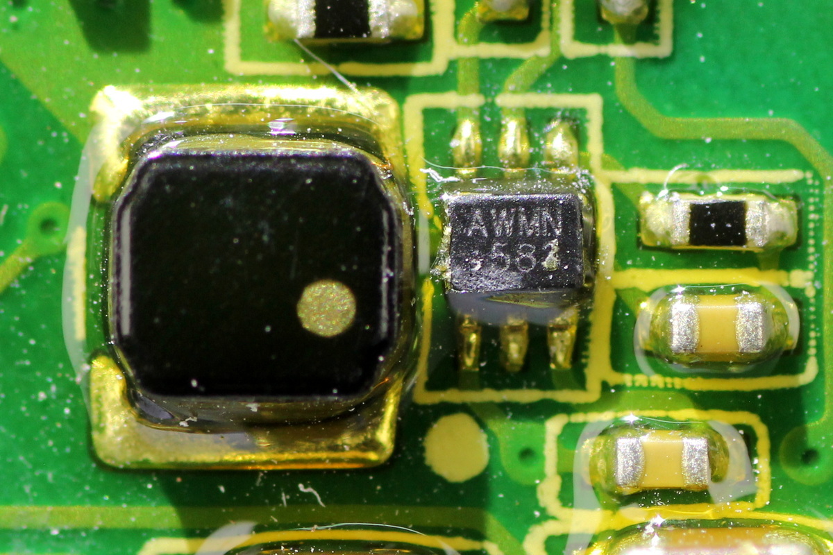
The synchronous buck converter is from MPS, model MP1654, marked AWM and housed in a SOT563 package.
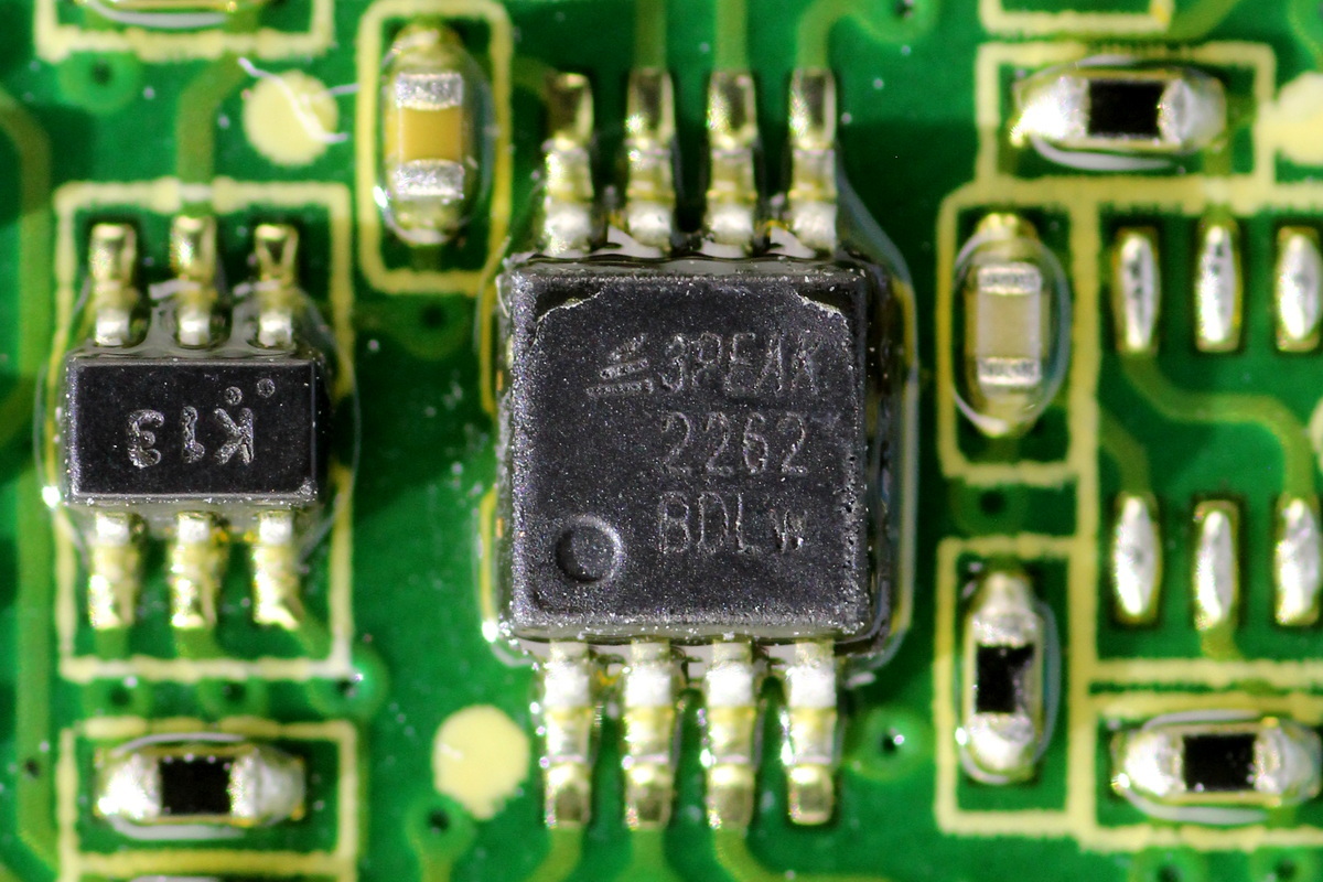
The operational amplifier is the 3PEAK TP2262.
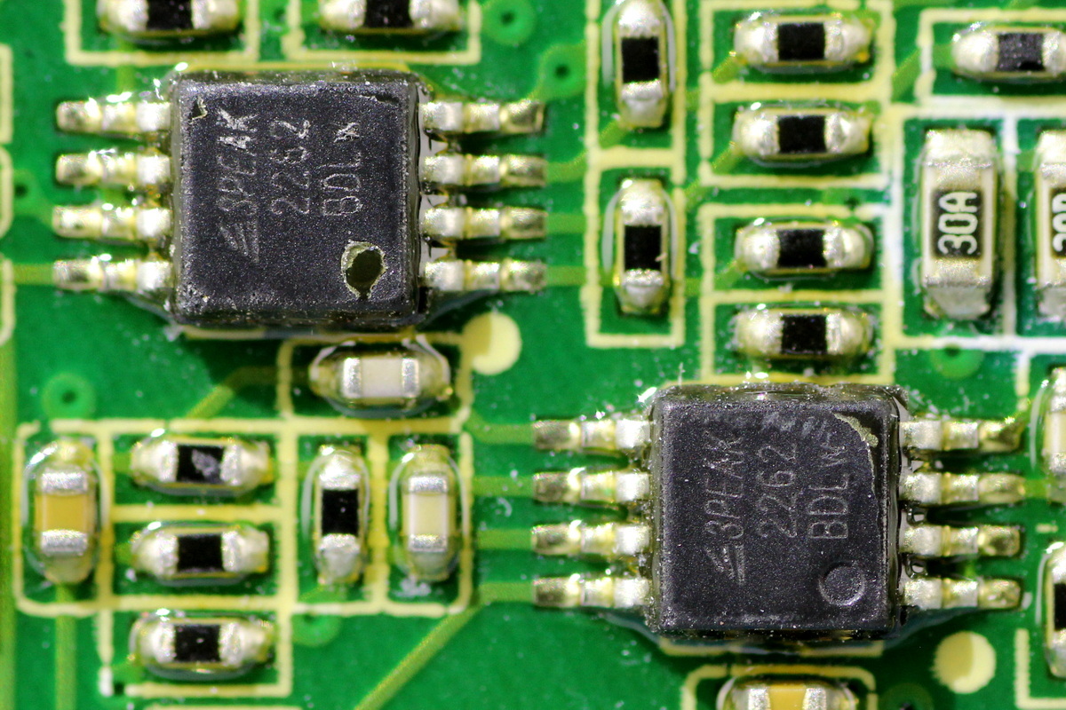
The two operational amplifiers share the same model.
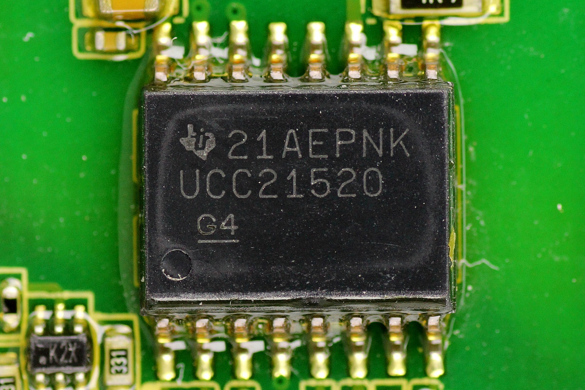
The isolated gate driver is from TI, model UCC21520, an isolated dual-channel gate driver with 5.7kVRMS isolation. It provides 4A peak source current and 6A peak sink current, can drive MOSFETs, IGBTs, and SiC MOSFETs, supports switching frequencies up to 5MHz, and comes in an SOIC16DW package.
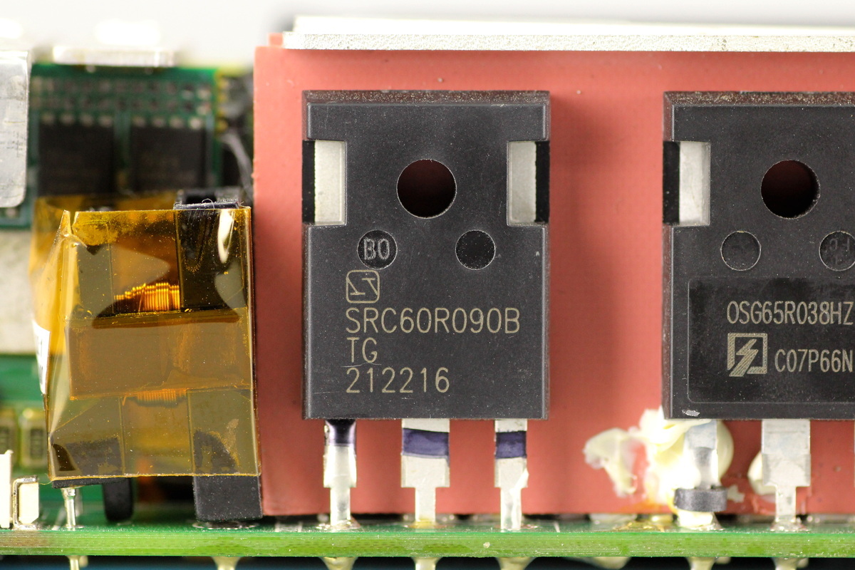
The LLC MOSFET is from Sanrise, model SRC60R090B, NMOS, 600V and 90mΩ, housed in a TO-247 package.
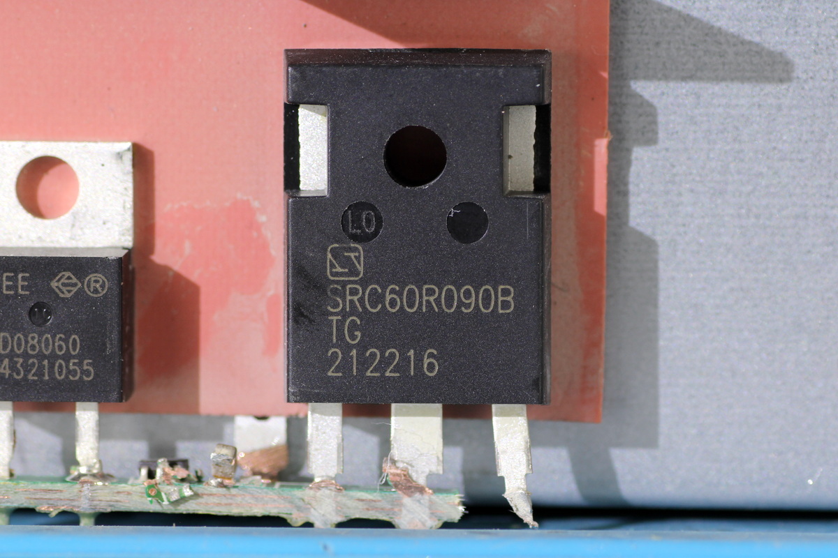
The other one shares the same model.

The current transformer is wrapped with high-temperature adhesive tape for insulation.
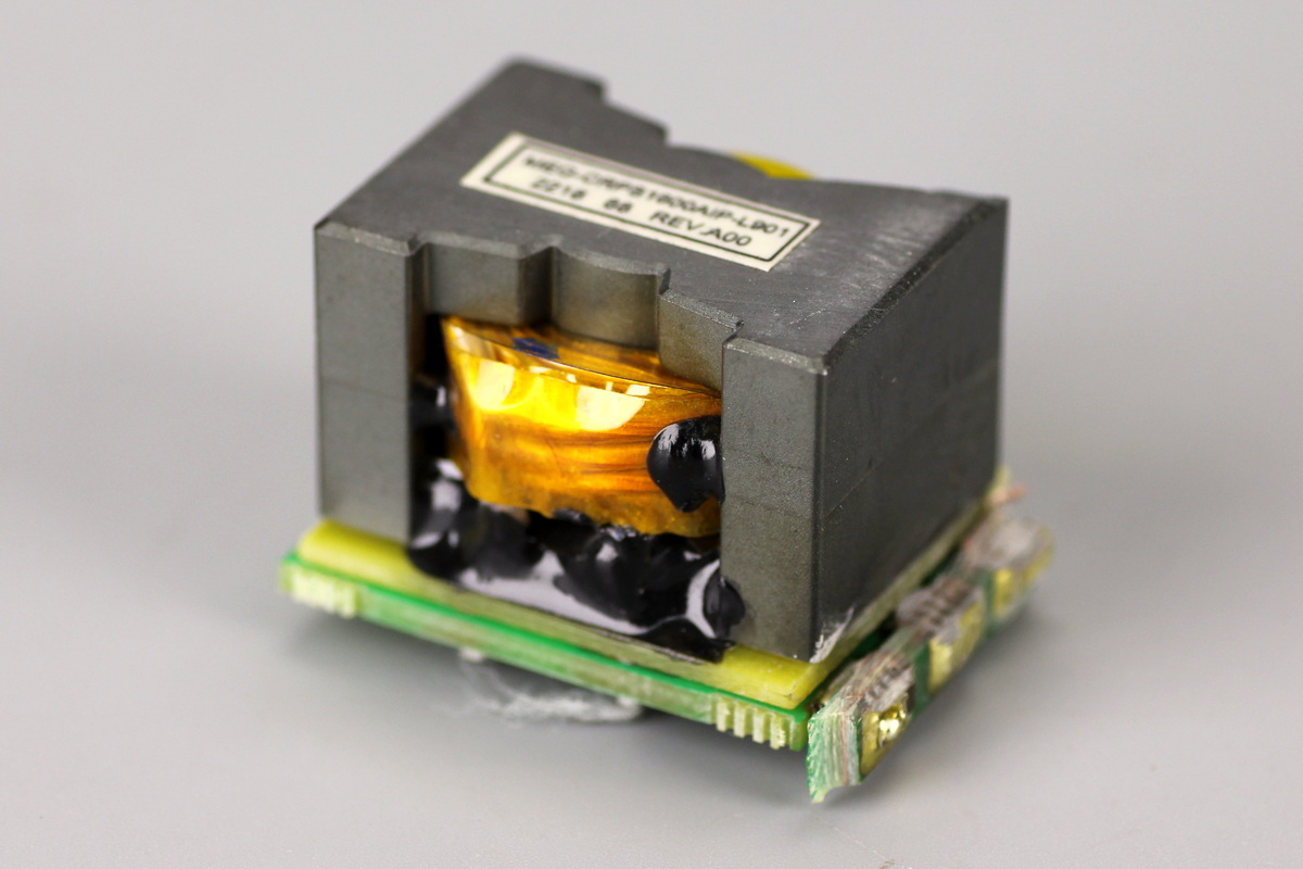
A resonant inductor is soldered to one side of the PCB.
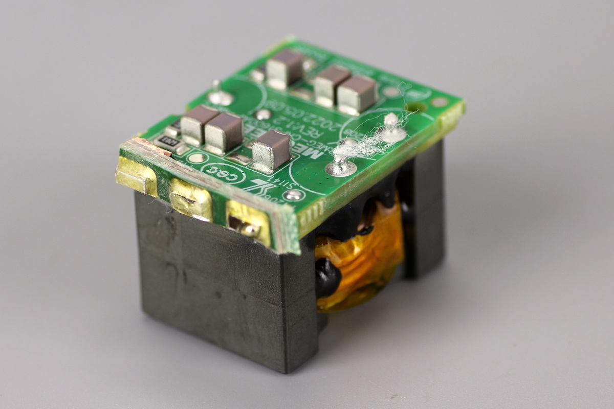
The resonant cap is soldered to the other side.
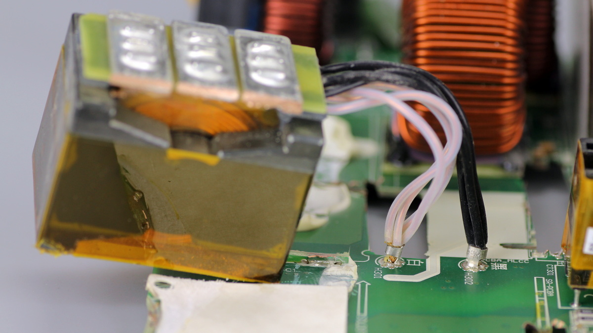
The primary winding of the transformer uses insulated wire, while the secondary uses soldered copper busbars.
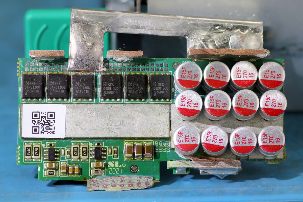
The synchronous rectification PCB contains synchronous rectifier MOSFETs, drivers, and filter caps.
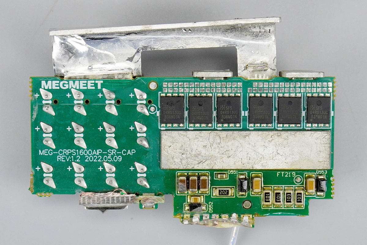
Additional synchronous rectifier MOSFETs are soldered on the other side.
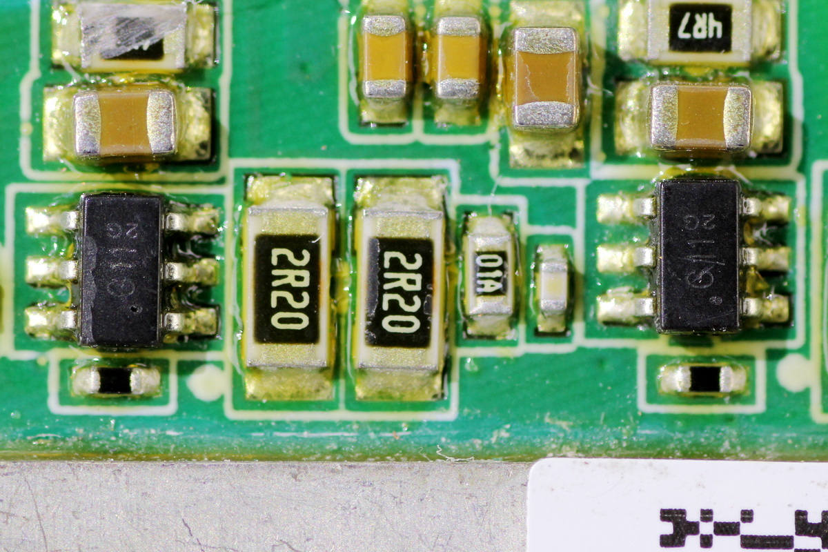
The two drivers are marked G11 and come in SOT23 packages.
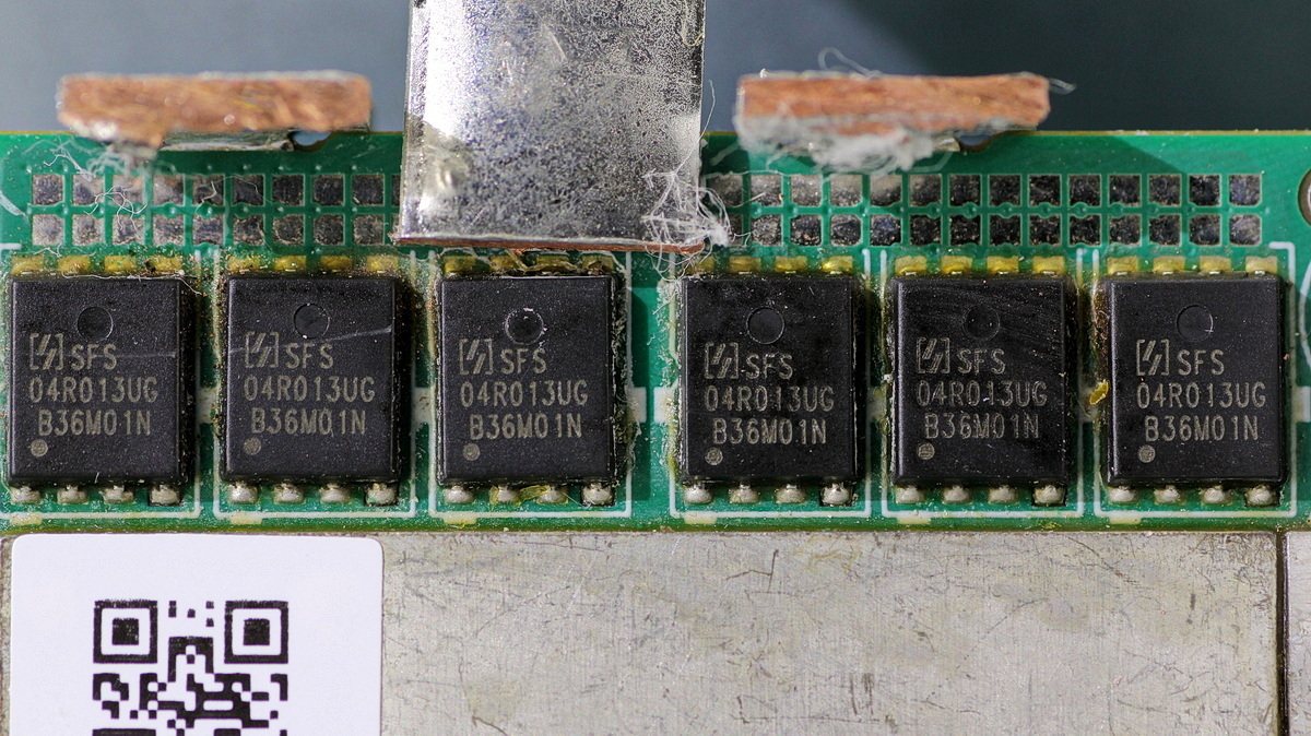
The synchronous rectifier MOSFETs are from Oriental, model SFS04R013UGF, NMOS, 40V and 1.1mΩ, and come in PDFN5×6 packages.
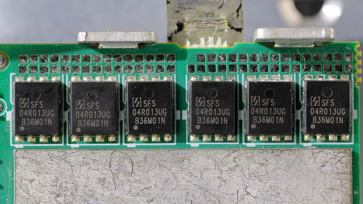
The six synchronous rectifier MOSFETs on the back are the same model.
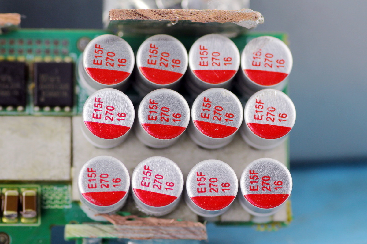
The filter cap is from AiSHi. It is a PF-series conductive polymer solid cap rated at 270μF 16V.
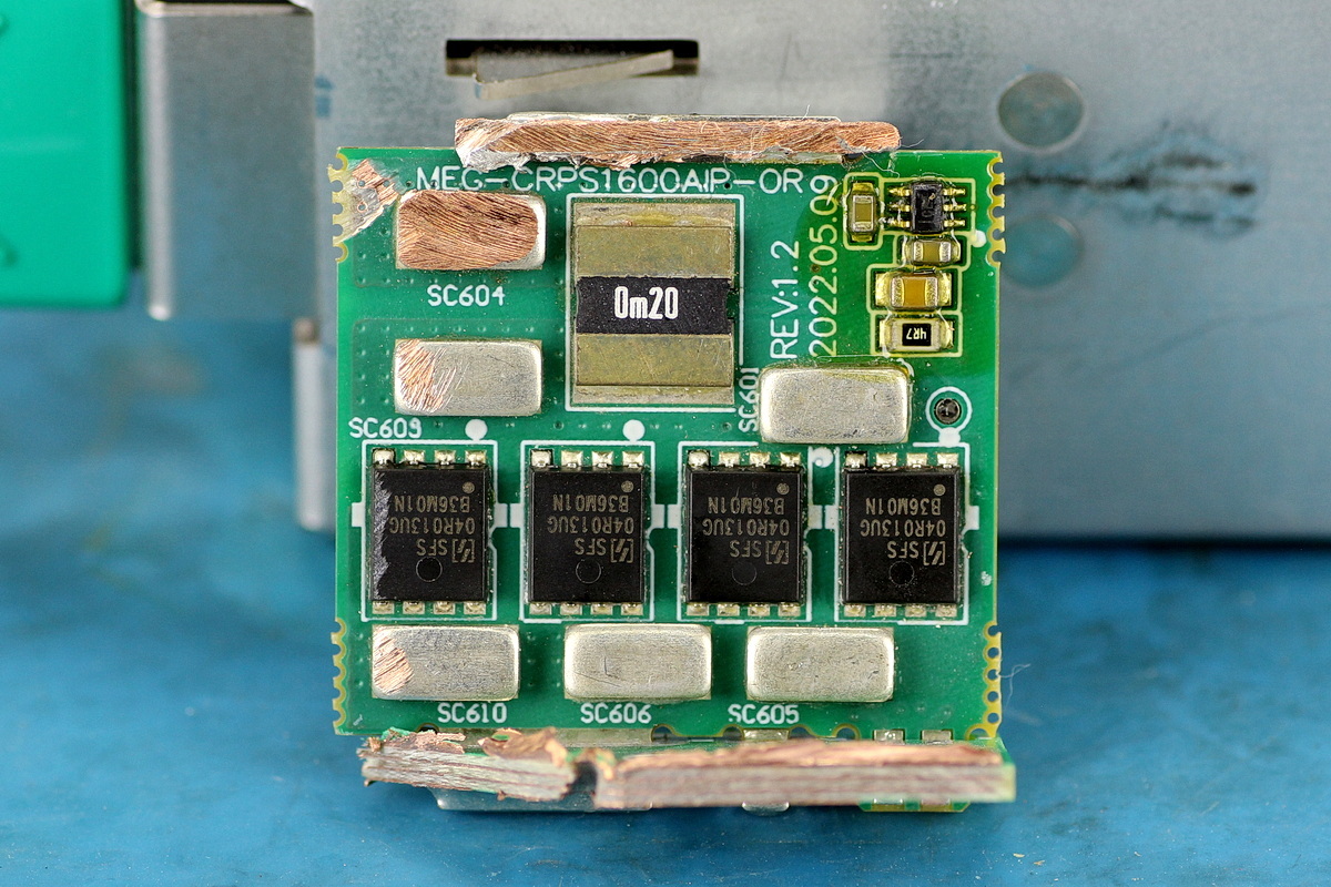
The ORing PCB is used for output control and contains current-sense resistors and output control MOSFETs.
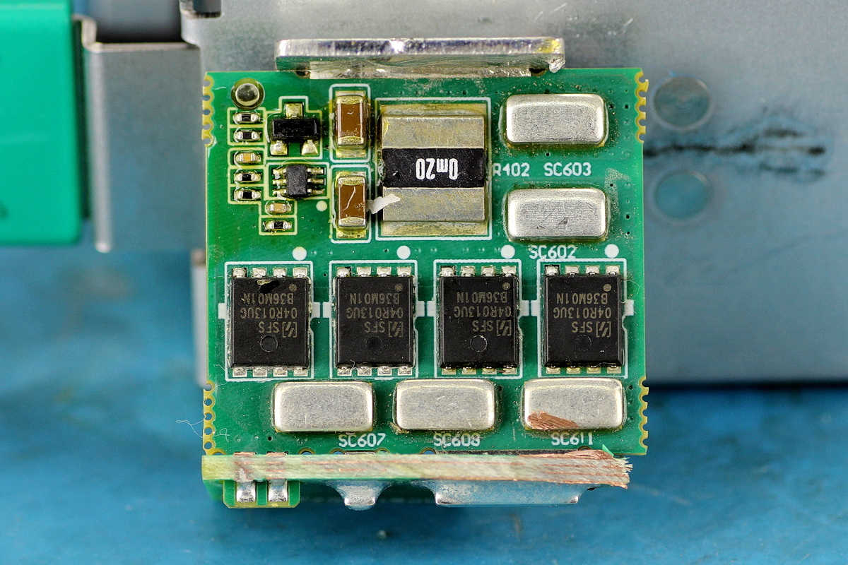
The other side also contains current-sense resistors and output control MOSFETs.

The output control MOSFET is from Oriental, model SFS04R013UGF, the same model used for synchronous rectification.
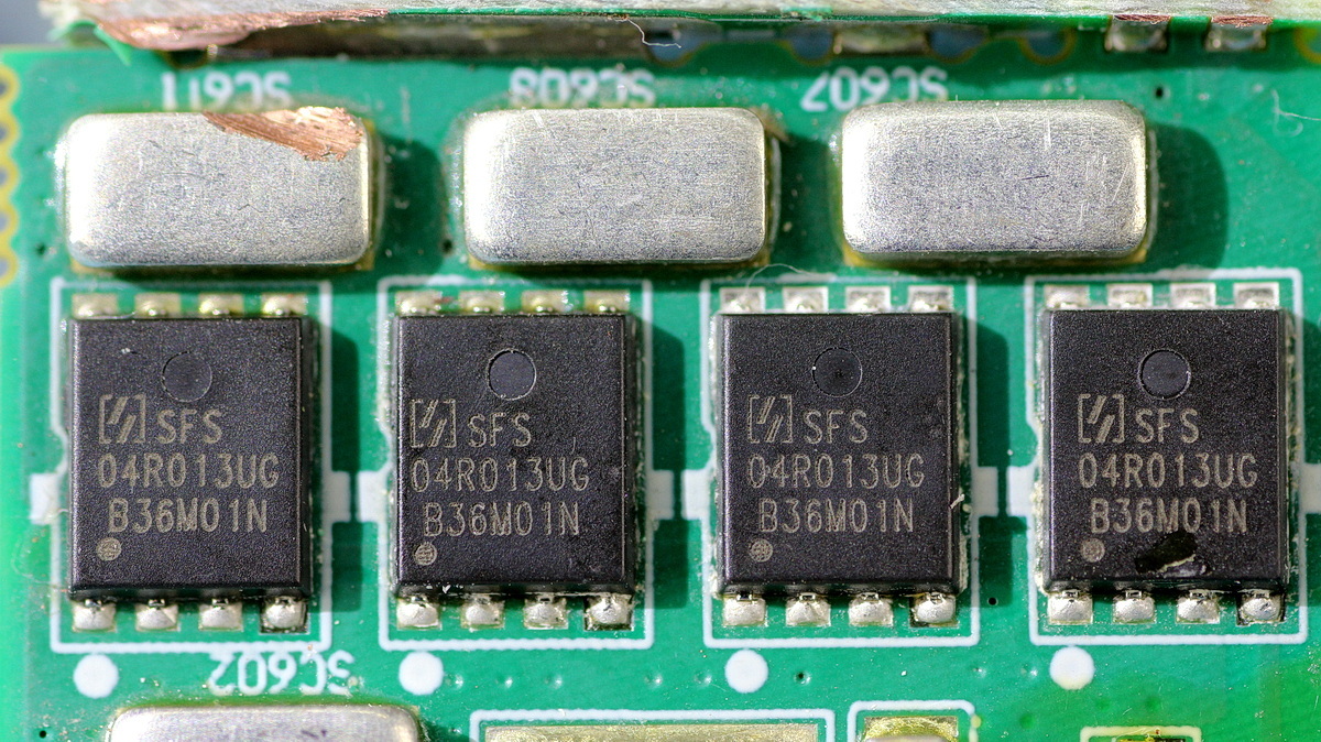
The four MOSFETs on the other side share the same model.
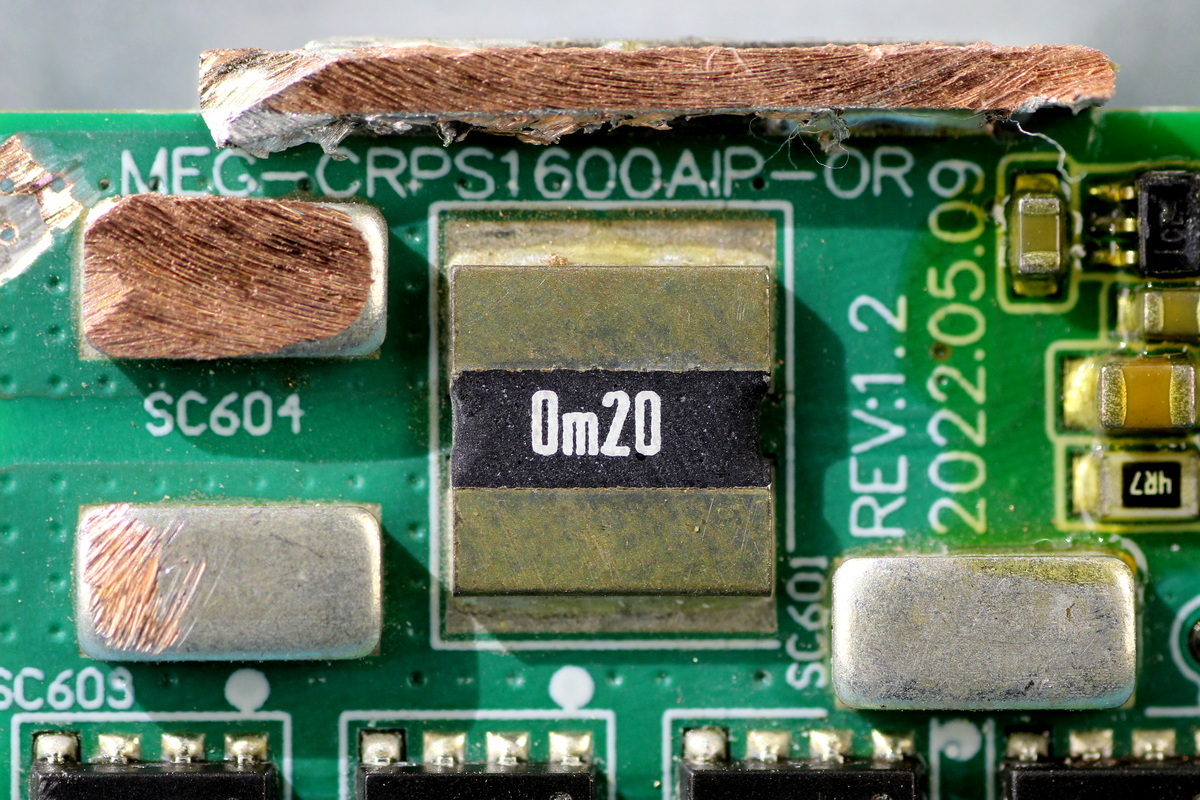
The 0.2mΩ current-sense resistor.
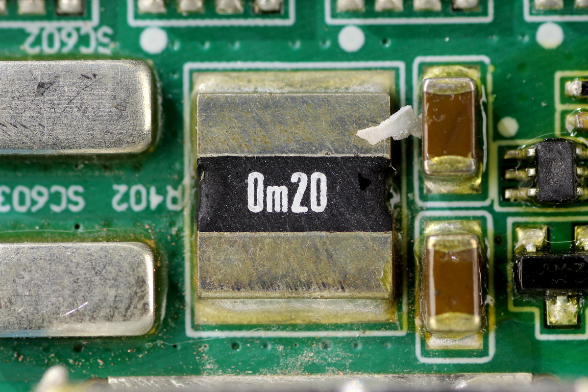
The other one shares the same rating.
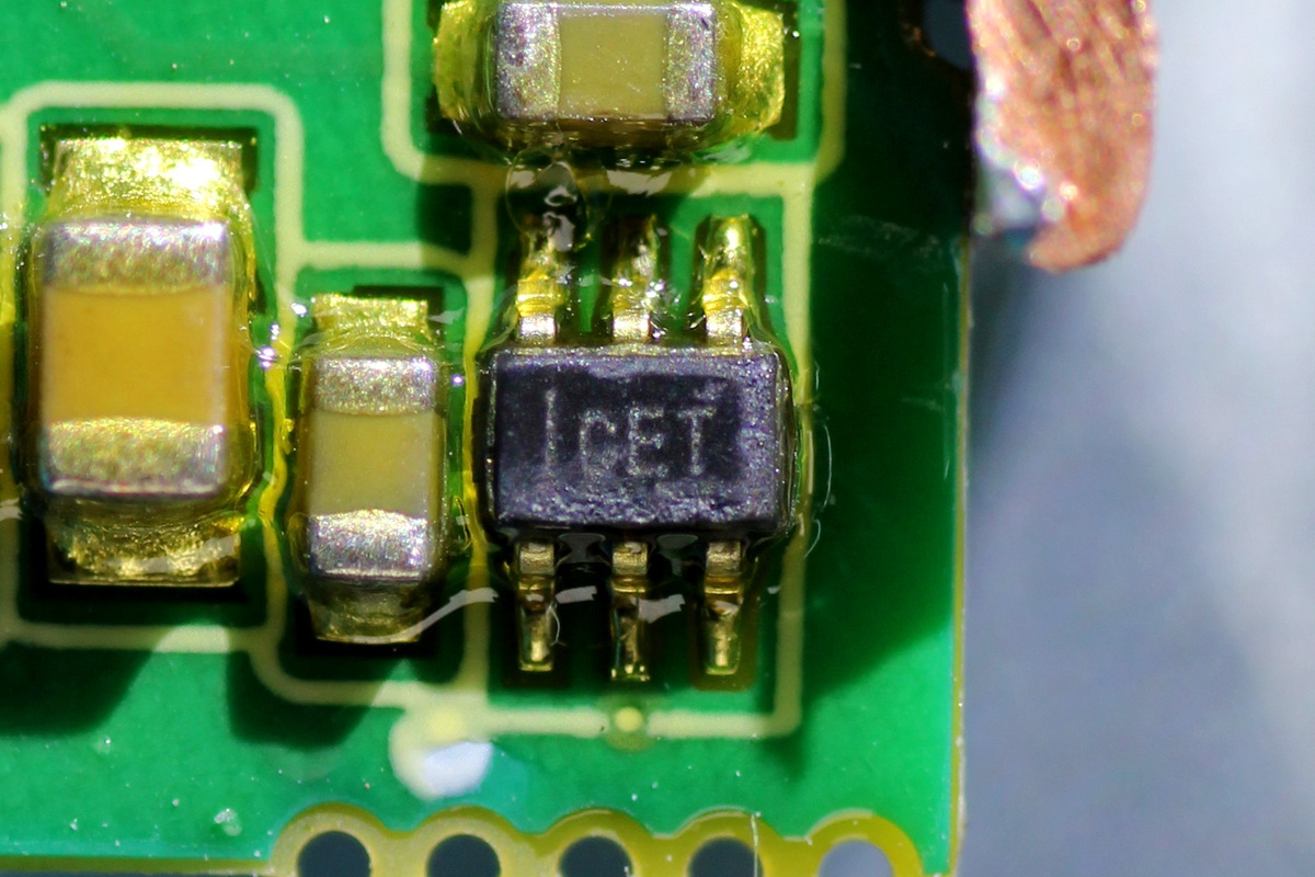
The current-sense chip is from TI INA210, marked CET. It is a 26V bidirectional high-precision current-sense amplifier in an SC70 package.
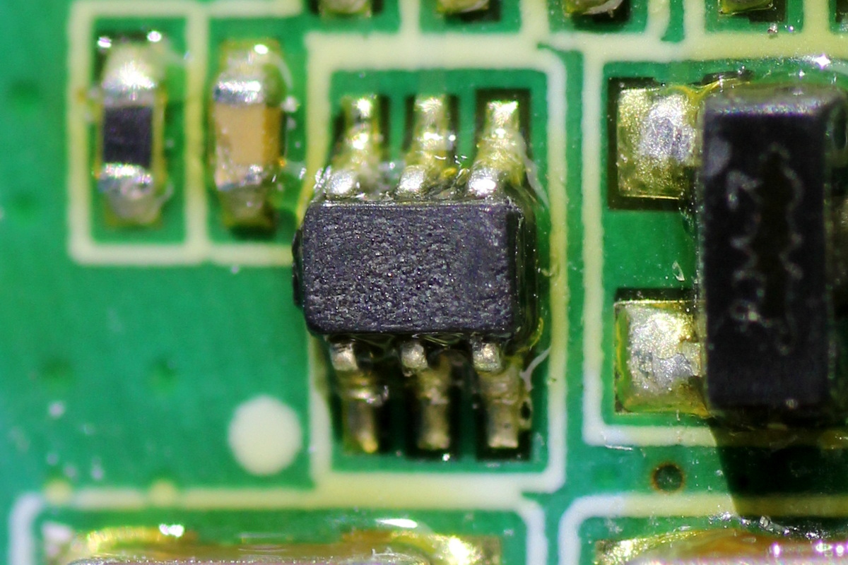
The chip marking is illegible.
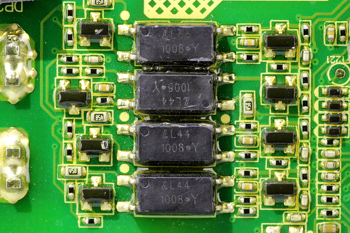
The LITEON LTV-1008 optocoupler is used for isolated communication.
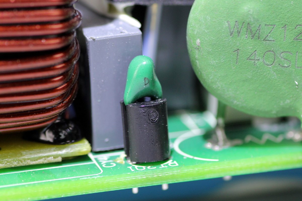
The thermistor is used to monitor the internal temperature of the power supply.
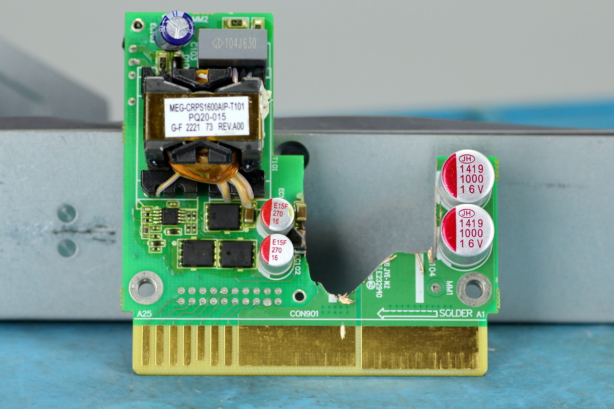
The front of the standby power supply PCB features a transformer, synchronous rectifier MOSFET, filter caps, and an output control MOSFET.
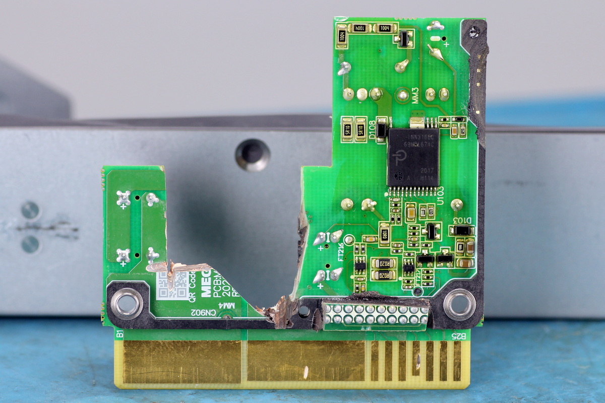
The standby power supply chip is located on the other side.
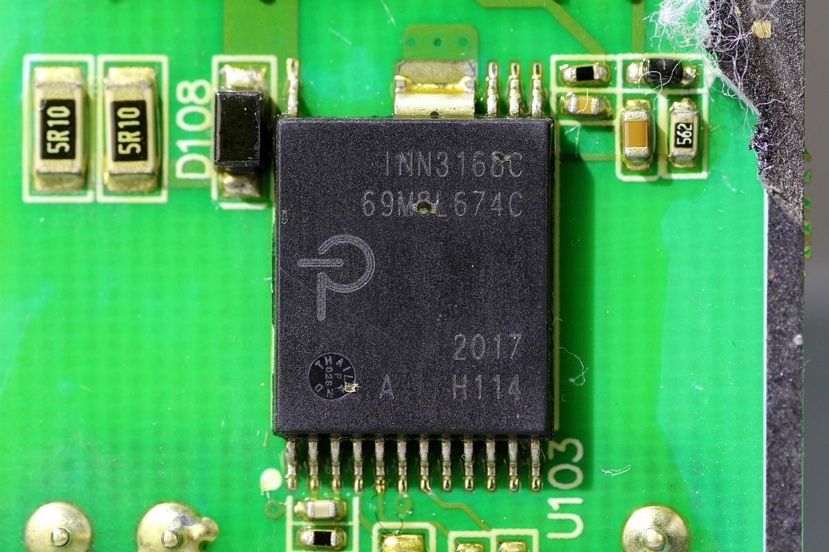
The standby power supply chip is from PI, model INN3168C, belonging to the InnoSwitch3-CE family. It integrates a 650V MOSFET, supports up to 50W output over a wide input voltage range, and comes in an InSOP-24D package.
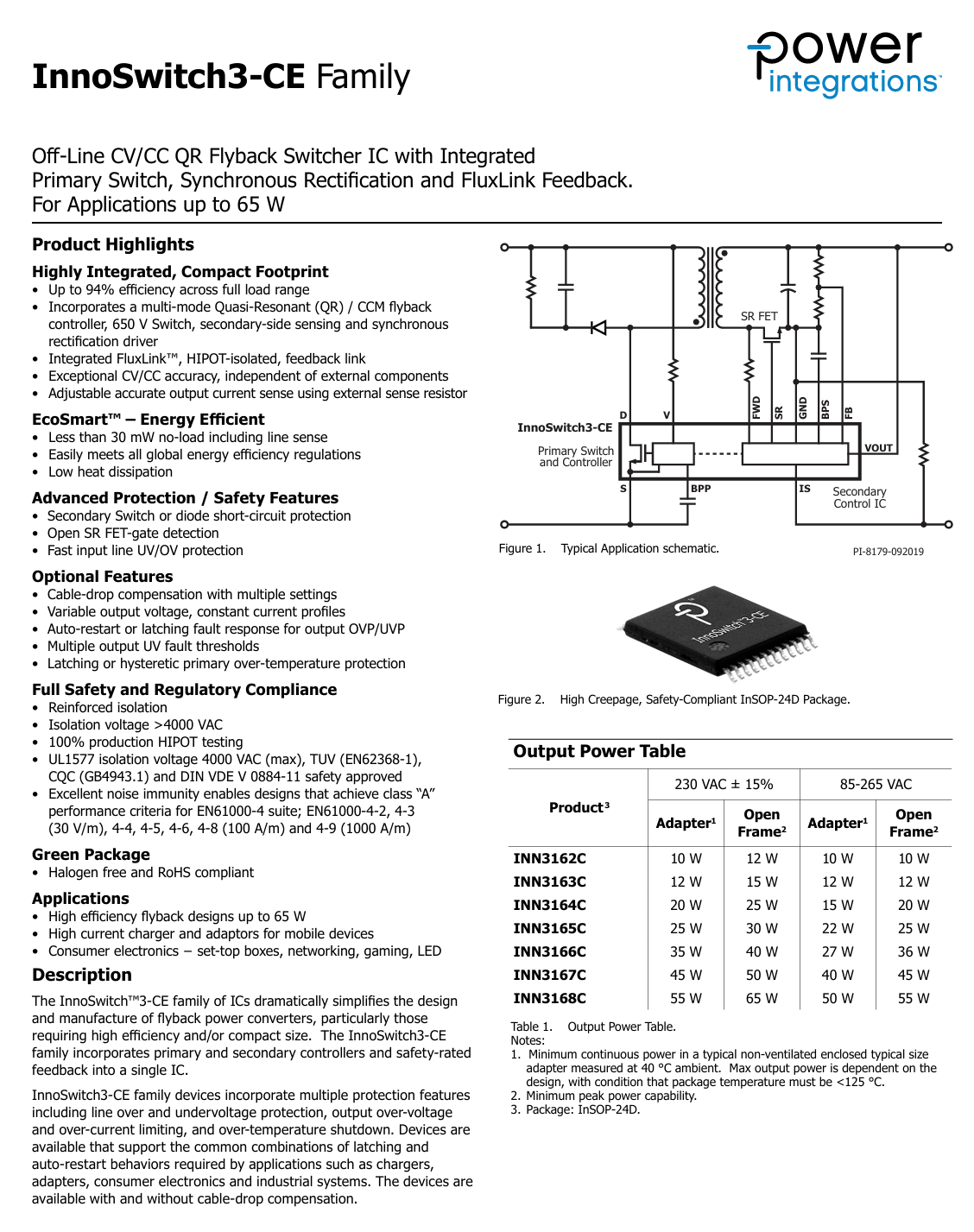
Here is the info about the PI INN3168C.
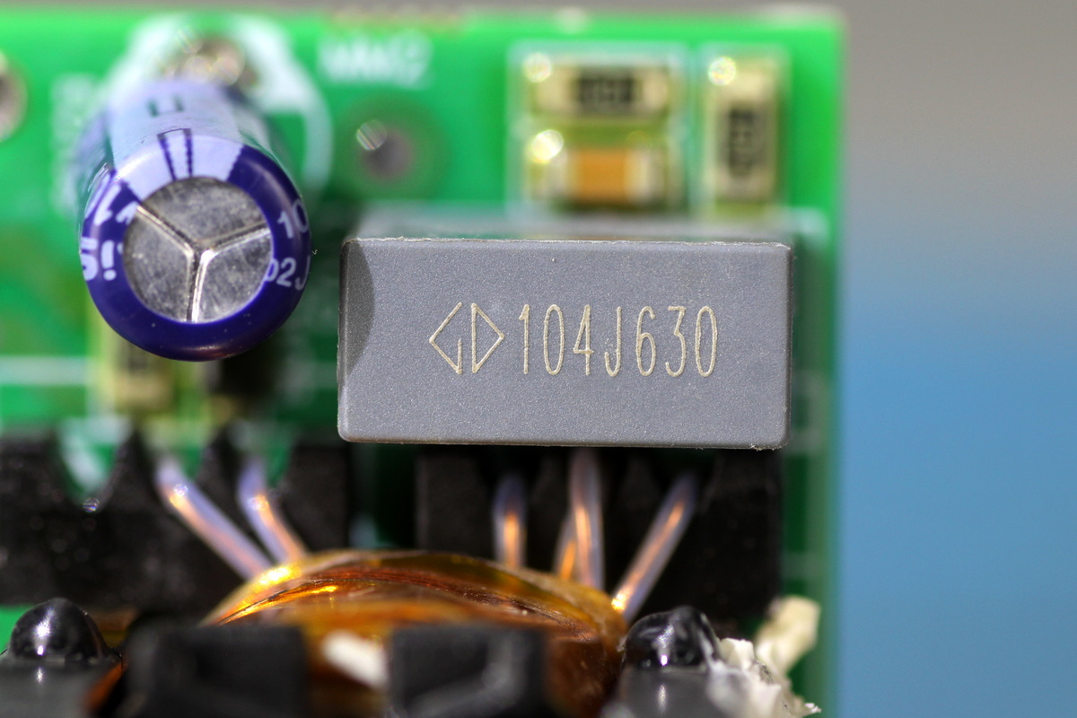
The film filter cap is from Faratronic and is rated at 0.1μF 630V.
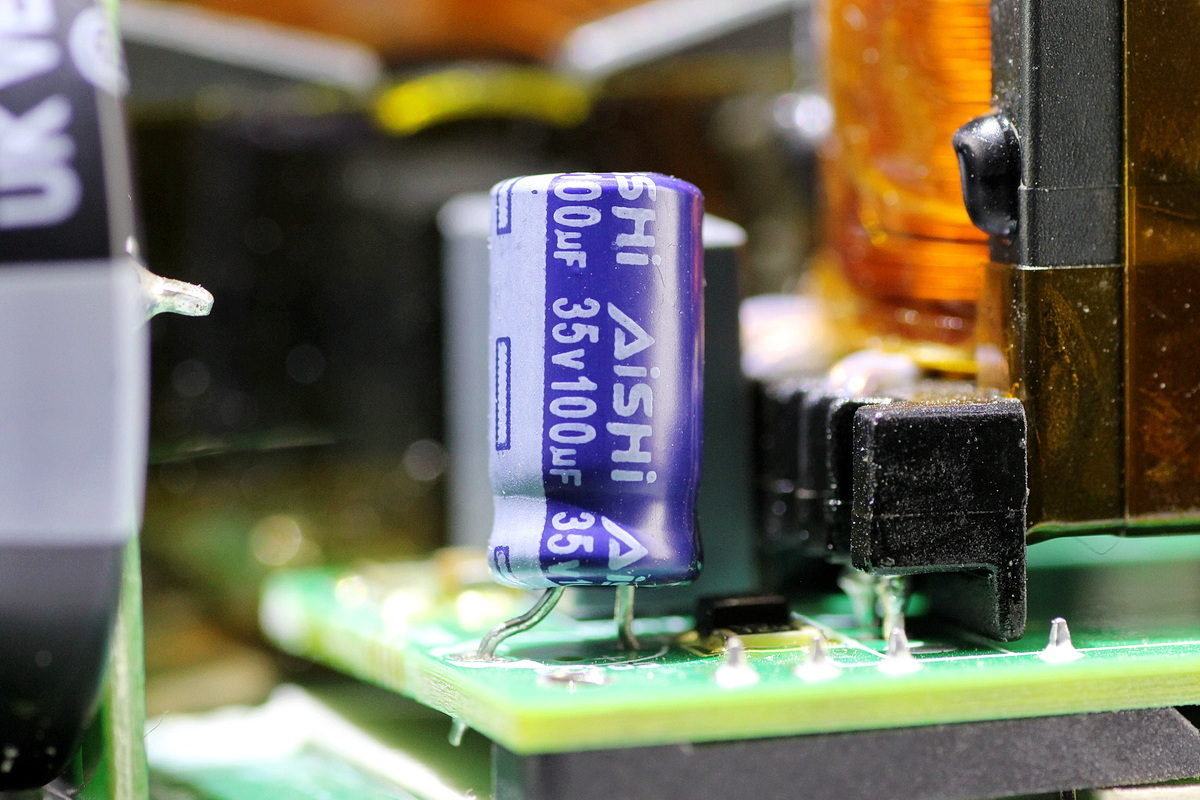
The filter cap is from AiSHi and is rated at 35V 100μF.
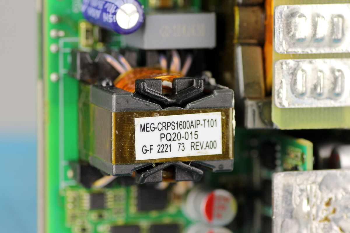
The transformer uses a PQ20 core.
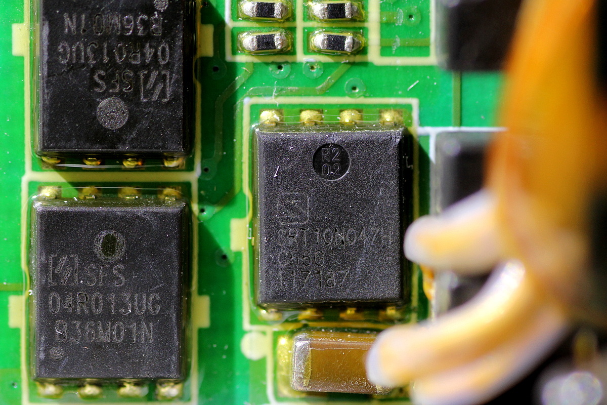
The synchronous rectifier MOSFET is from Sanrise, model SRT10N047H, NMOS, 100V and 4.7mΩ, housed in a PDFN5×6 package.
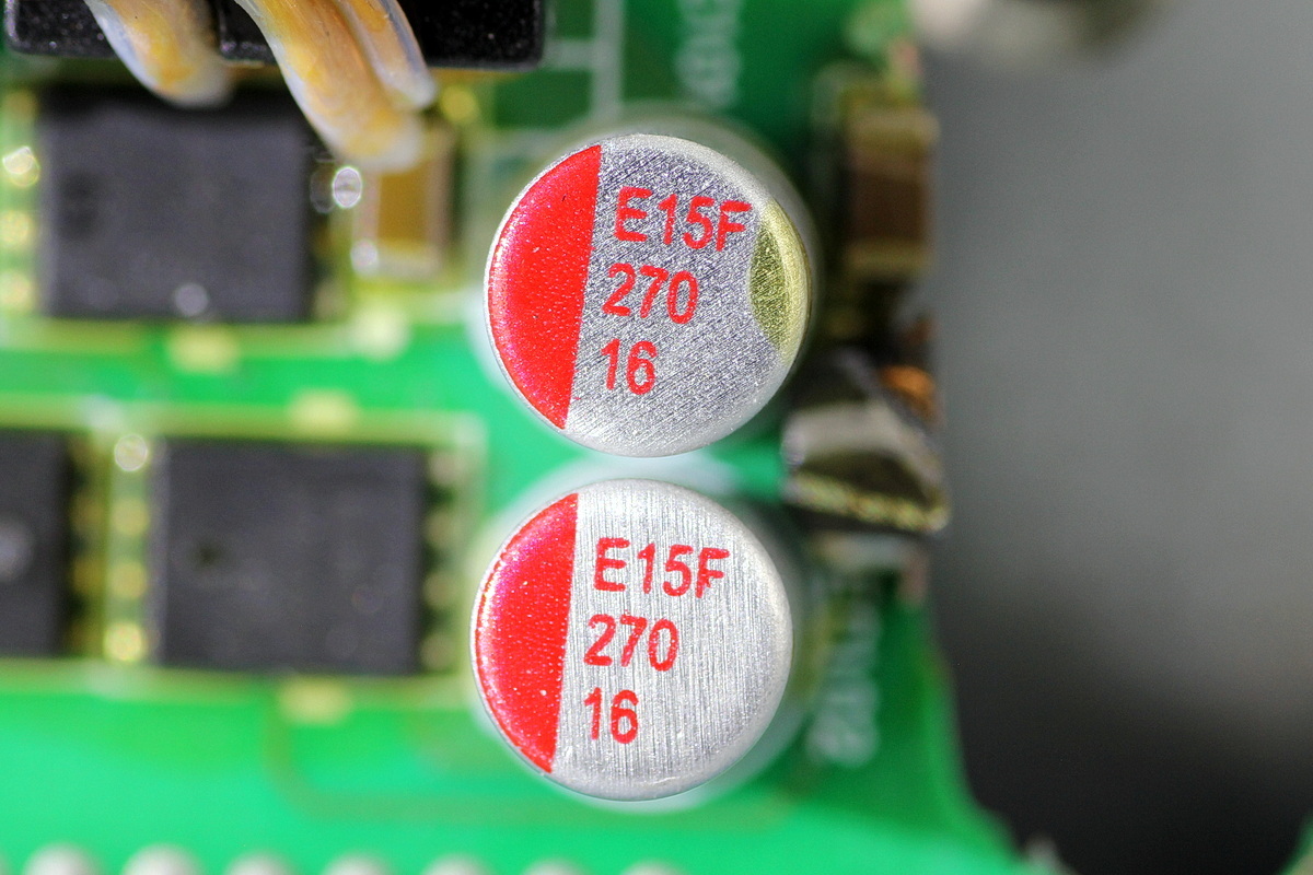
The filter cap is from AiSHi and is rated at 270μF 16V.
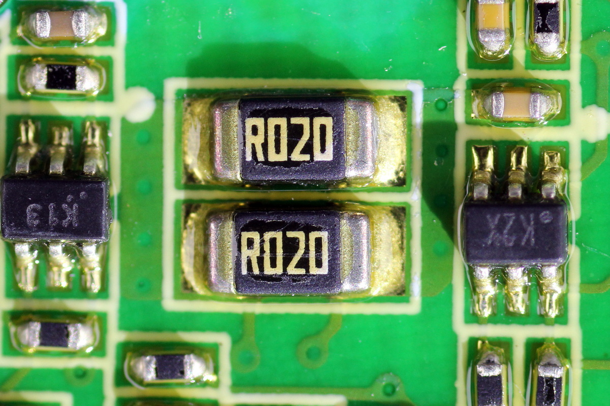
Two 20mΩ resistors are connected in parallel for output current sensing.
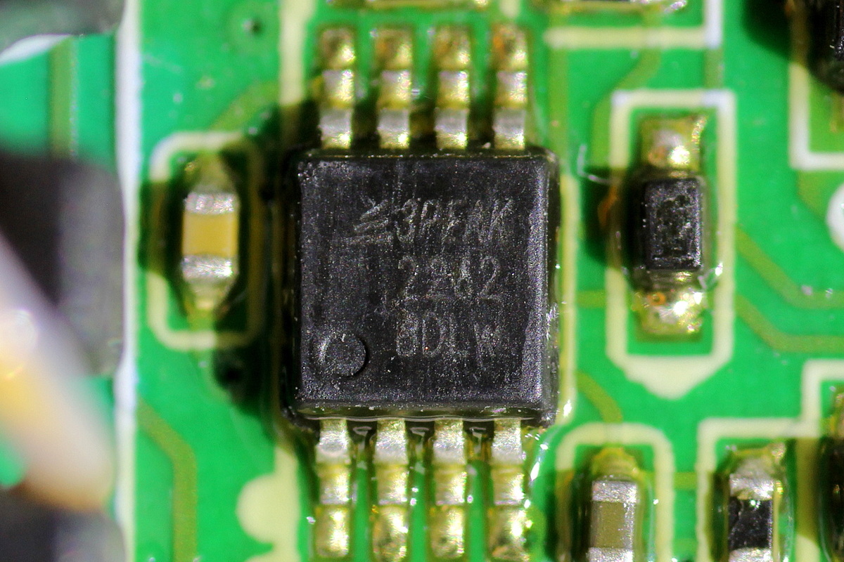
The operational amplifier is the 3PEAK TP2262.
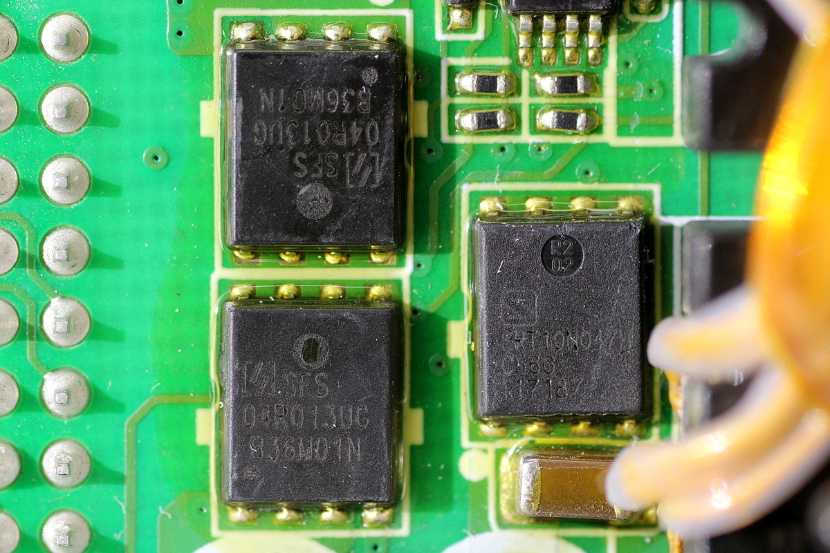
The output control MOSFET is from Oriental, model SFS04R013UGF, the same model used for synchronous rectification.
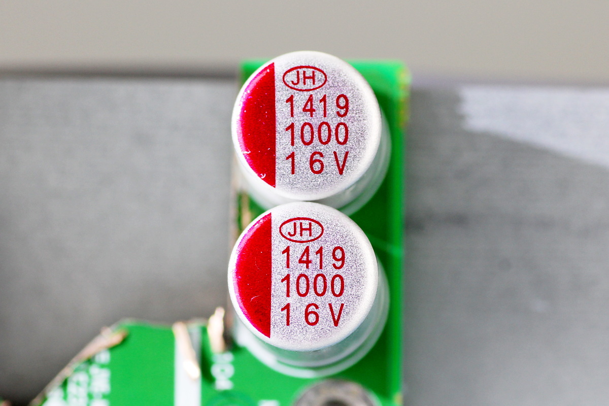
The two filter caps are from Jianghai and are rated at 1000μF 16V.
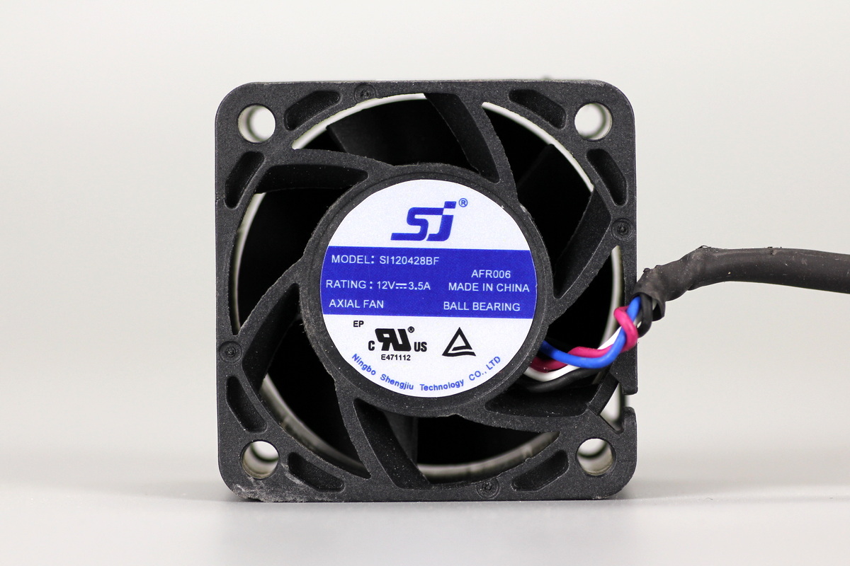
The cooling fan is from Shengjiu, model SI120428BF, rated at 12V 3.5A and equipped with ball bearings.
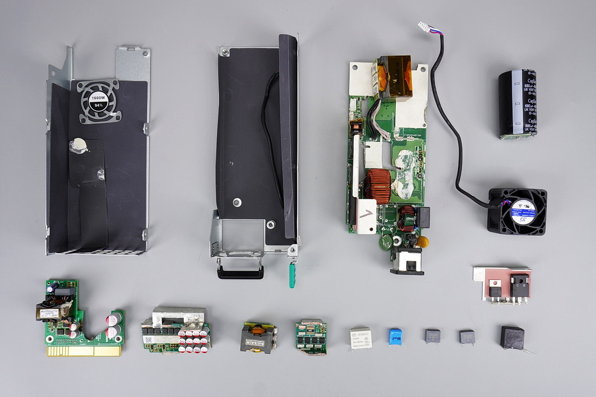
Well, those are all components of the MEGMEET 1600W SiC CRPS Server Power Supply (MEG-CRPS1600AIP).
Summary of ChargerLAB
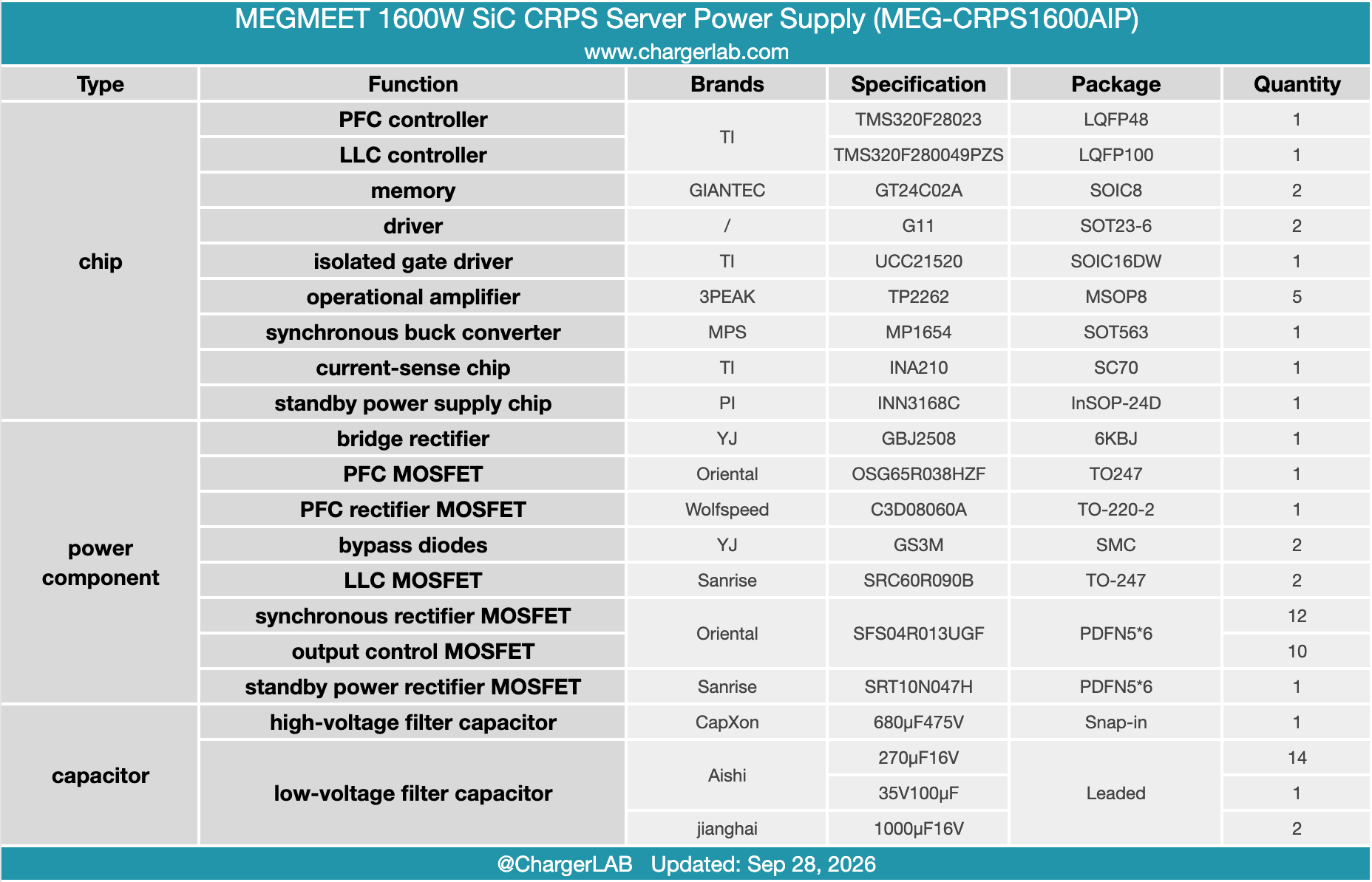
The Megmeet 1600W SiC CRPS Server Power Supply (Model: MEG-CRPS1600AIP) accommodates 100–120V and 200–240V AC inputs alongside 240V DC input. It delivers a main 12V rail at 133A, complemented by an auxiliary standby output of 12V at 2.5A.
A comprehensive teardown by ChargerLAB reveals a robust PFC + half-bridge LLC + synchronous rectification topology. PFC control is anchored by a TI TMS320F28023 MCU, partnering with an Oriental OSG65R038HZF MOSFET and a CREE C3D08060A silicon carbide diode.
The LLC stage relies on a TI TMS320F280049PZS real-time controller and a UCC21520 isolated driver to govern Sanrise SRC60R090B MOSFETs, alongside Oriental SFS04R013UGF synchronous rectifiers. Standby power conversion is driven by a PI INN3168C IC. To maximize durability, the PCBA is sealed with conformal coating and structural adhesive, reflecting meticulous, industrial-grade engineering.
Related Articles:
1. Teardown of MEGMEET 600W Switching Power Supply (MSP600)
2. Top 5 AI Power Supply Companies in the First Half of 2026
3. Teardown of MEGMEET MR750‑20V 15 kW DC Charging Module