
Introduction
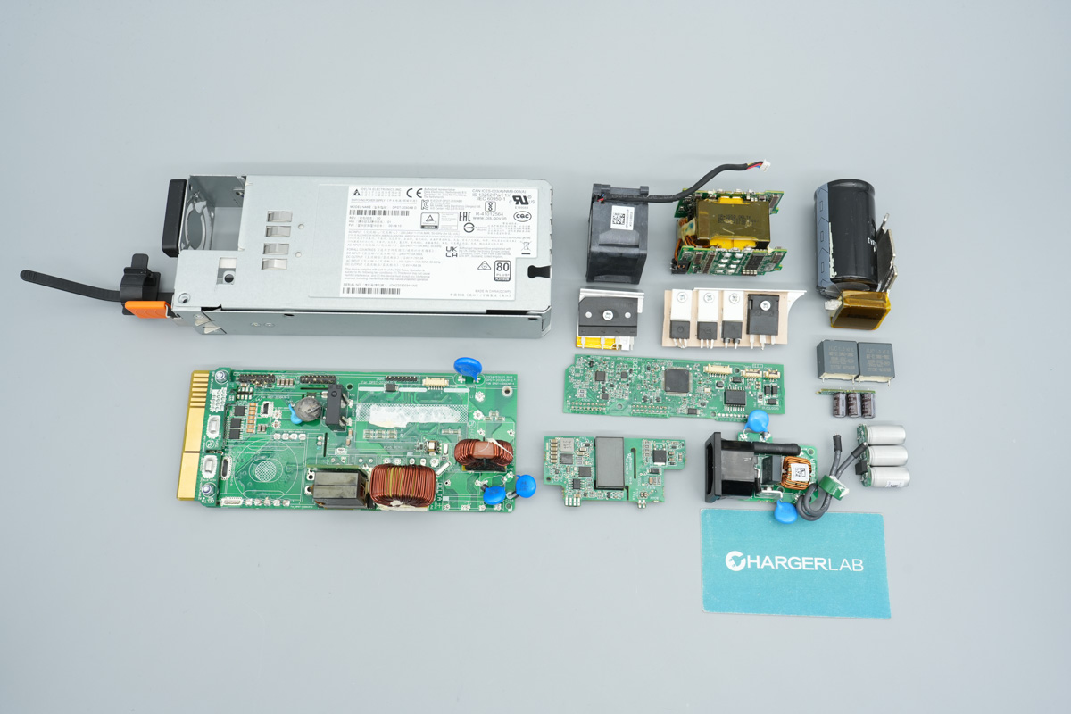
Today's teardown showcases the DELL 1300W Workstation Power Supply. Built by Delta (Model: D1300EF-02), it accepts a 100–240V AC input to deliver a robust 1300W maximum output. It features ten 12V output rails (up to 216W per rail), a -12V rail, and a 12V/6A standby rail.
The input end integrates an AC socket, cooling fan, test button, LED indicator, and release latch, while the output end features a gold-finger edge connector and ventilation grilles. Operating with an 80 PLUS Gold efficiency rating, the internal topology utilizes an interleaved PFC, phase-shifted full-bridge (PSFB), and synchronous rectification circuit. Let's dive inside to explore DELL's engineering and component layout.
Product Appearance
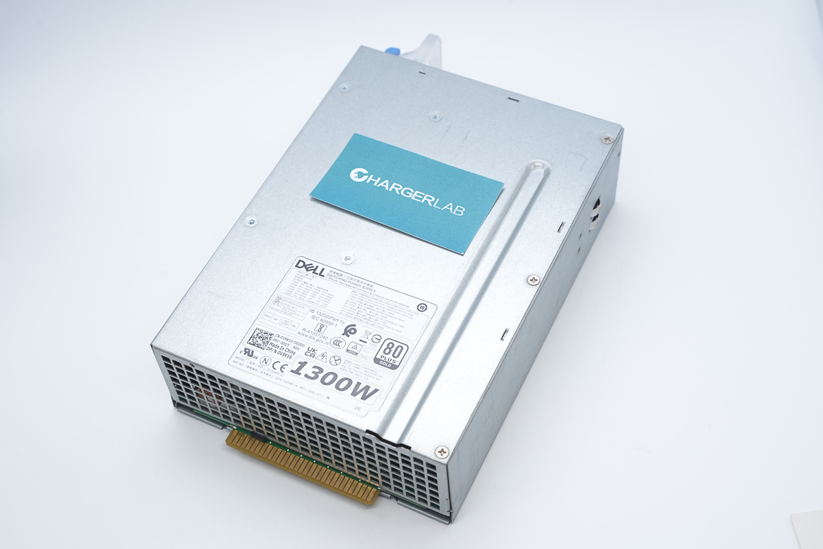
The DELL workstation power supply adopts a galvanized steel sheet housing, with an info label affixed to the front of the casing.

Input: 100-240V~ 14A 50-60Hz
Output: 1300W MAX
+12VA ⎓ /18A
+12VB ⎓ /18A
+12VC ⎓ /18A
+12VD ⎓ /18A
+12VE ⎓ /18A
+12VF ⎓ /18A
+12VG ⎓ /18A
+12VH ⎓ /18A
+12VI ⎓ /18A
+12VJ ⎓ /18A
-12V ⎓ /0.5A
+12VSB ⎓ /6A
Combined maximum output for +12VA, +12VB, +12VC, +12VD, +12VE, +12VF, +12VG, +12VH, +12VI, +12VJ, and +12VSB: 1300W
90–107Vac maximum output: 1000W
107.1–180Vac maximum output: 1100W
180.1–264Vac maximum output: 1300W
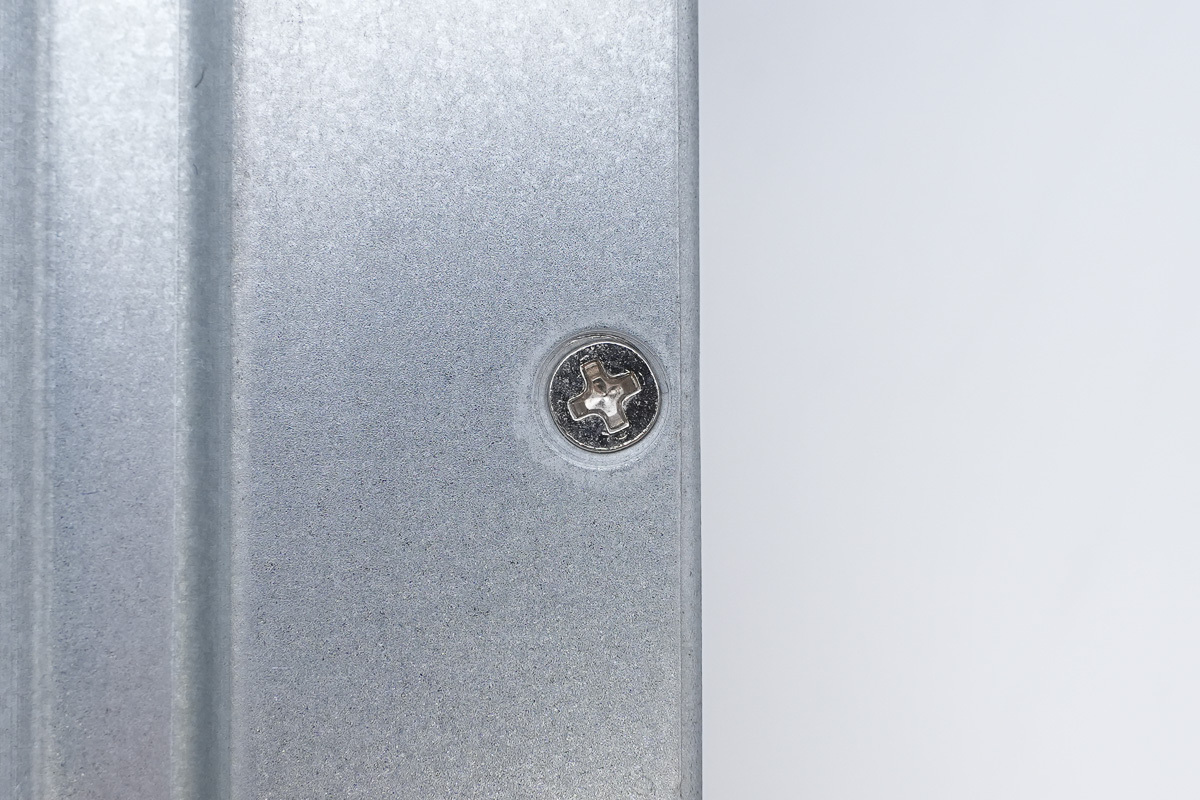
The housing cover plate is secured with screws.
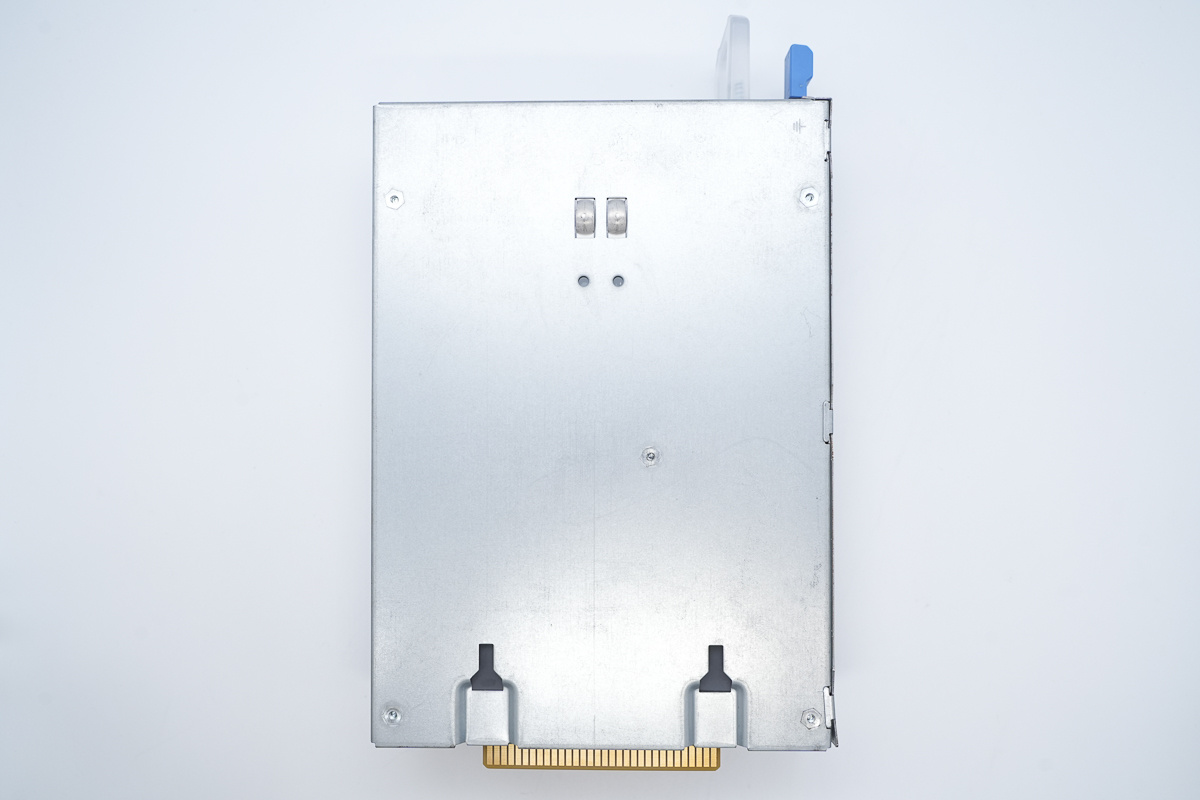
The back of the housing features a grounding protrusion.
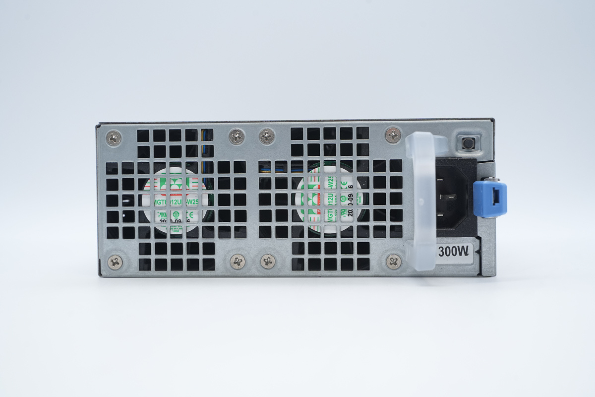
The input end is equipped with a cooling fan, LED indicator, test button, and AC power socket.
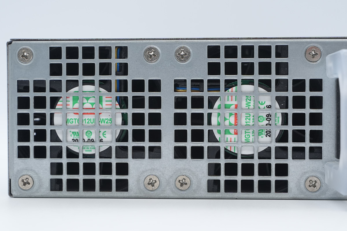
A cooling fan is installed inside the grille.
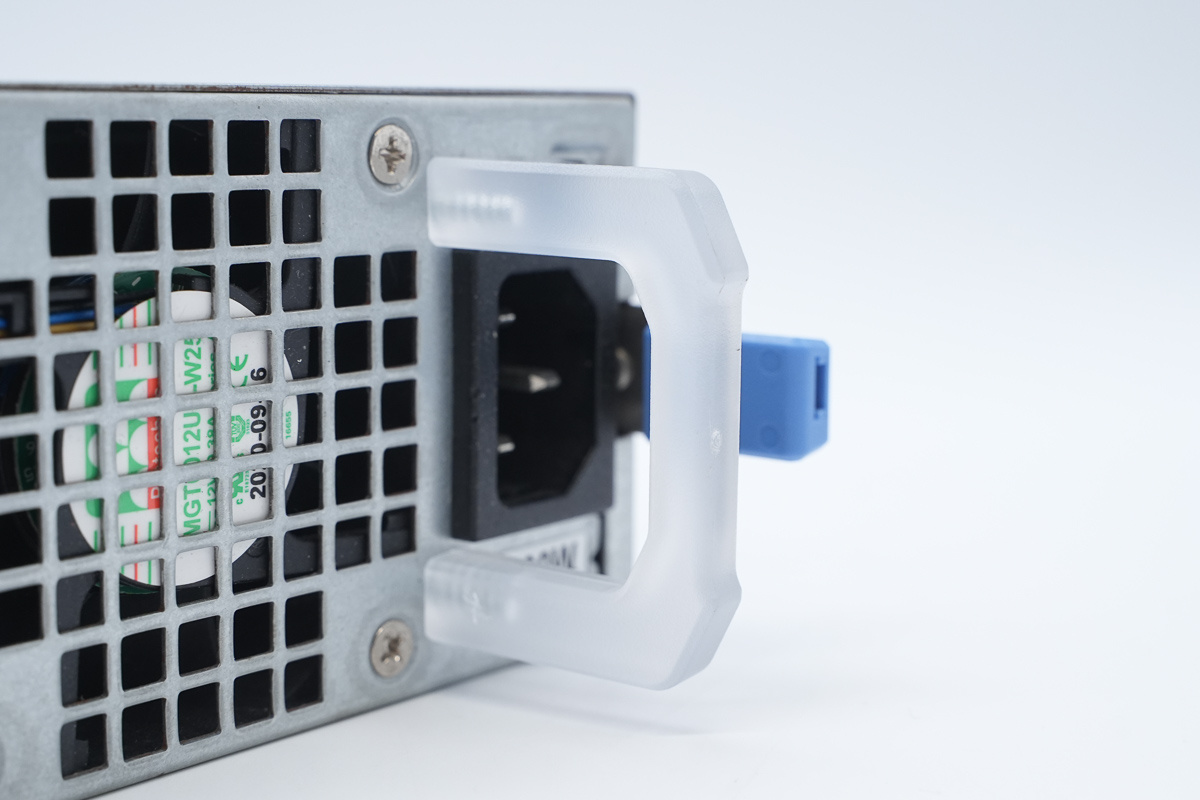
The handle is made of a semi-transparent material and also functions as an LED indicator.
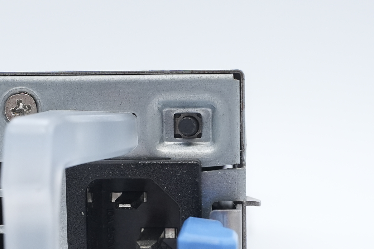
The test button.
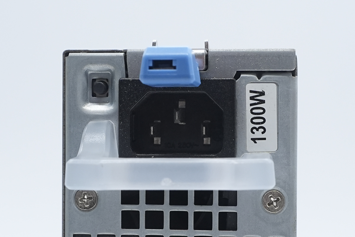
The IEC power socket.
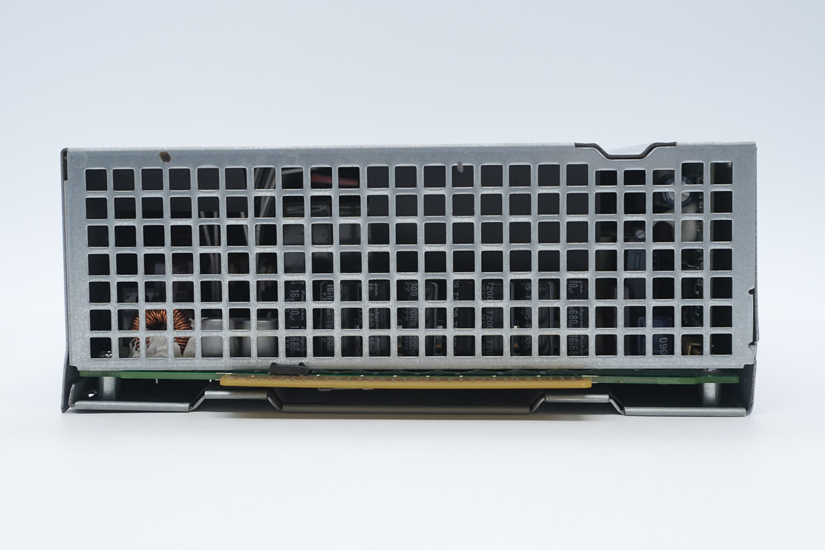
The output end is equipped with ventilation grilles and a gold-finger connector.
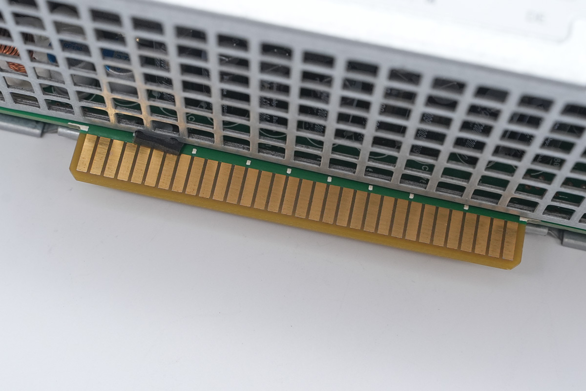
The gold-finger connector.
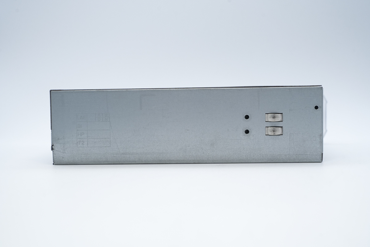
The side of the housing features grounding contact springs.
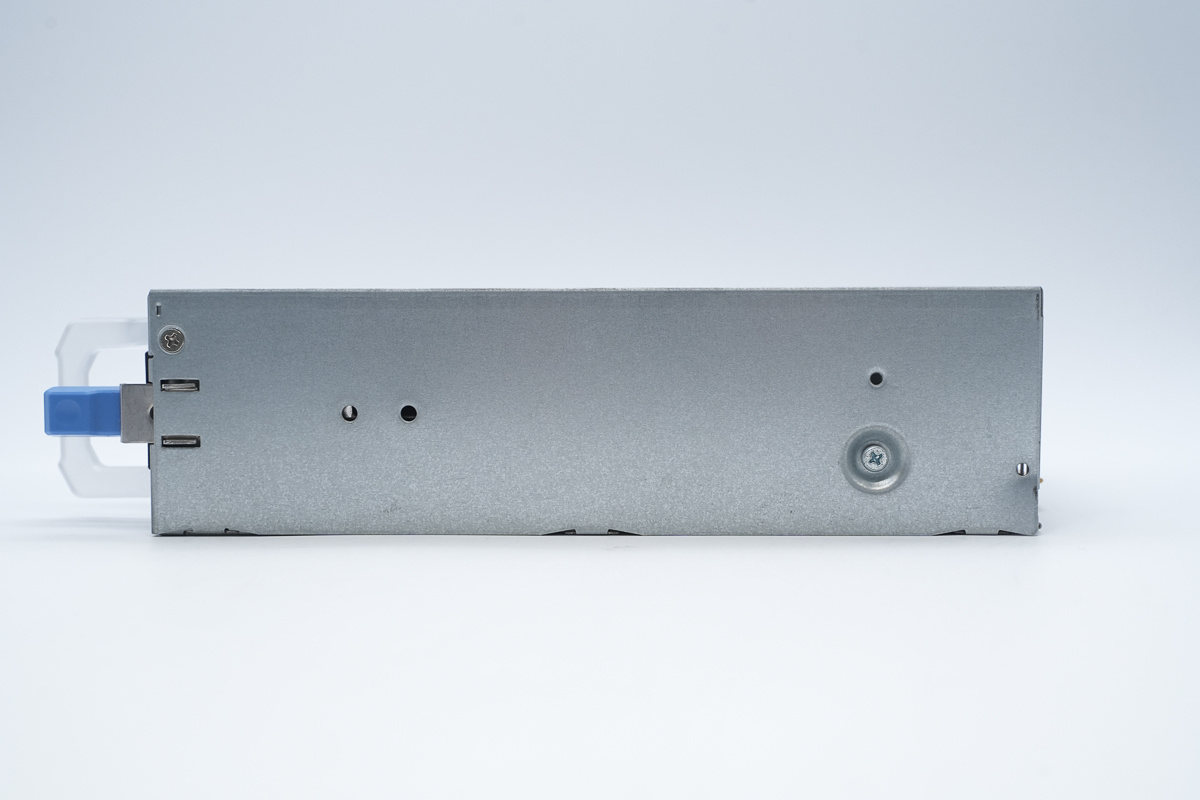
The side panel includes a locking latch and fixing screws.
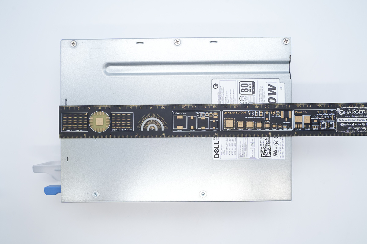
The length of the power supply is about 225mm (8.858 inches).
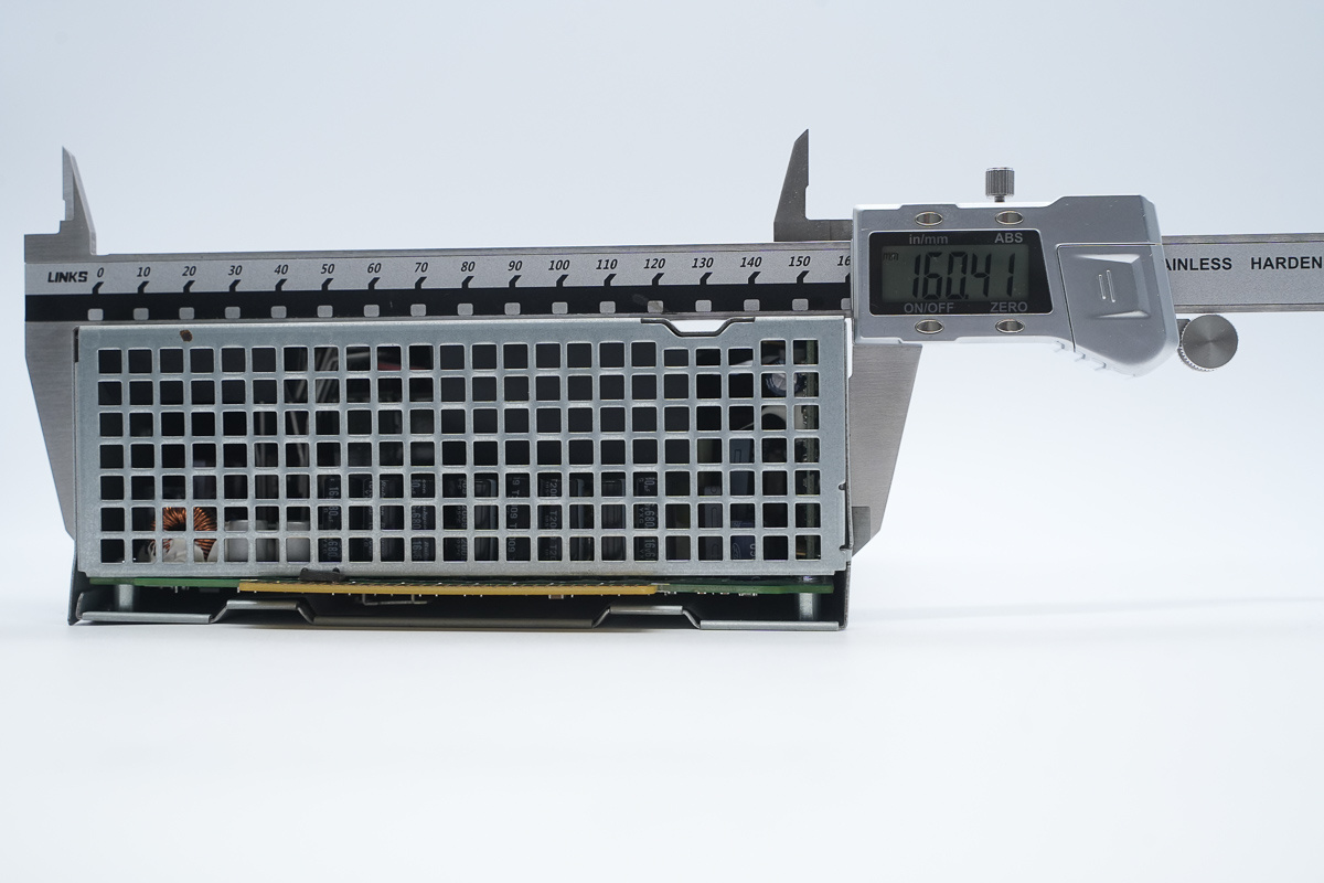
The width of the power supply is about 160.4mm (6.315 inches).
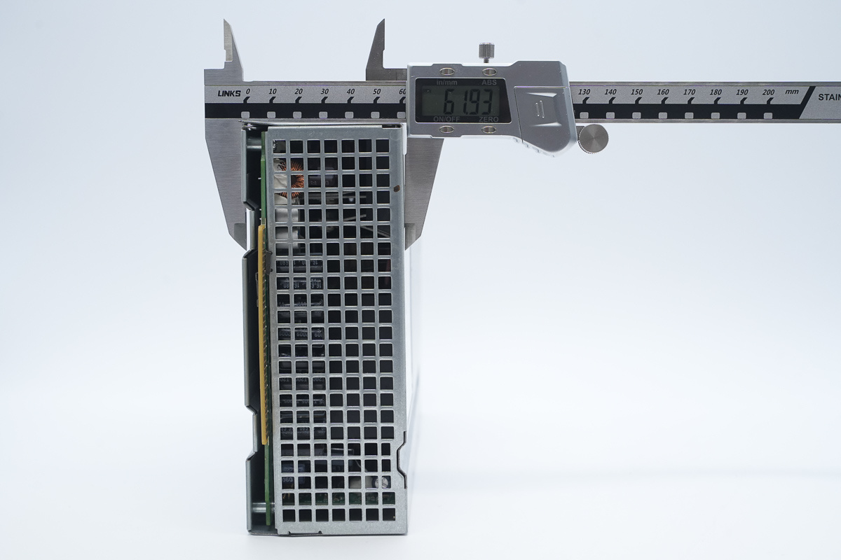
The thickness of the power supply is about 62mm (2.441 inches).
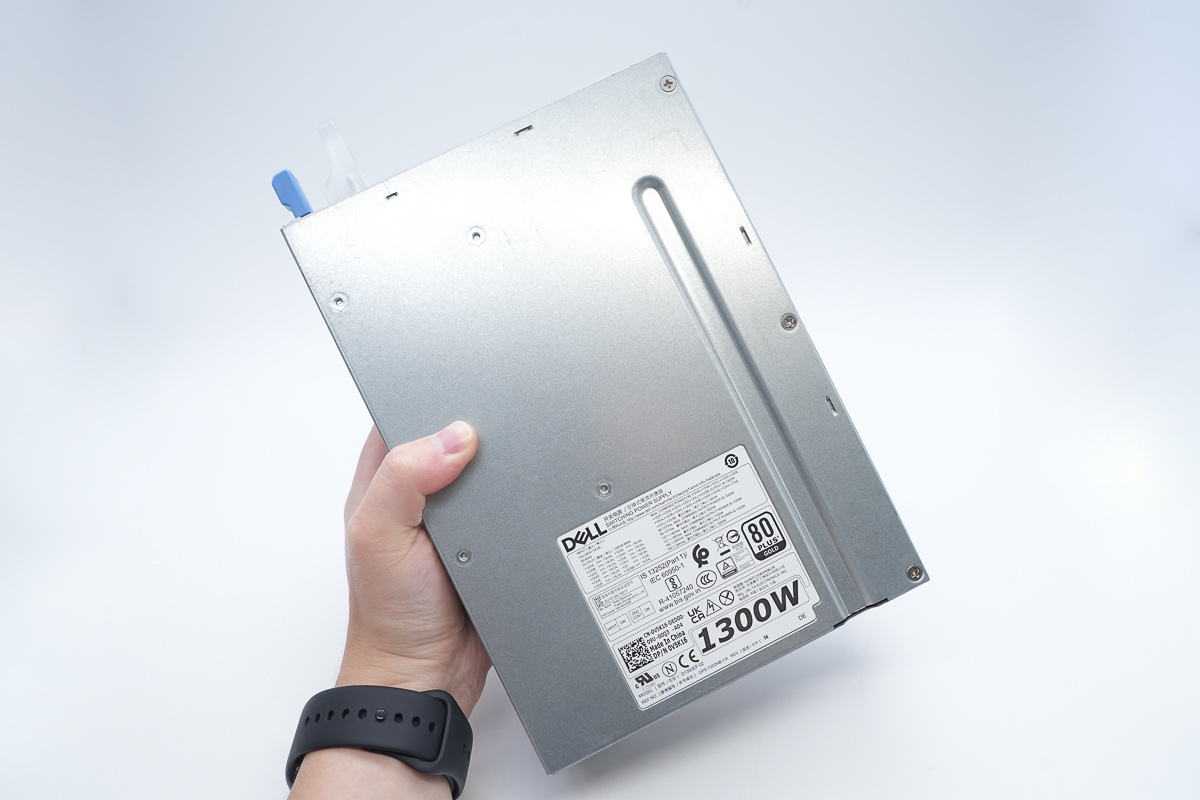
That's how big it is in the hand.
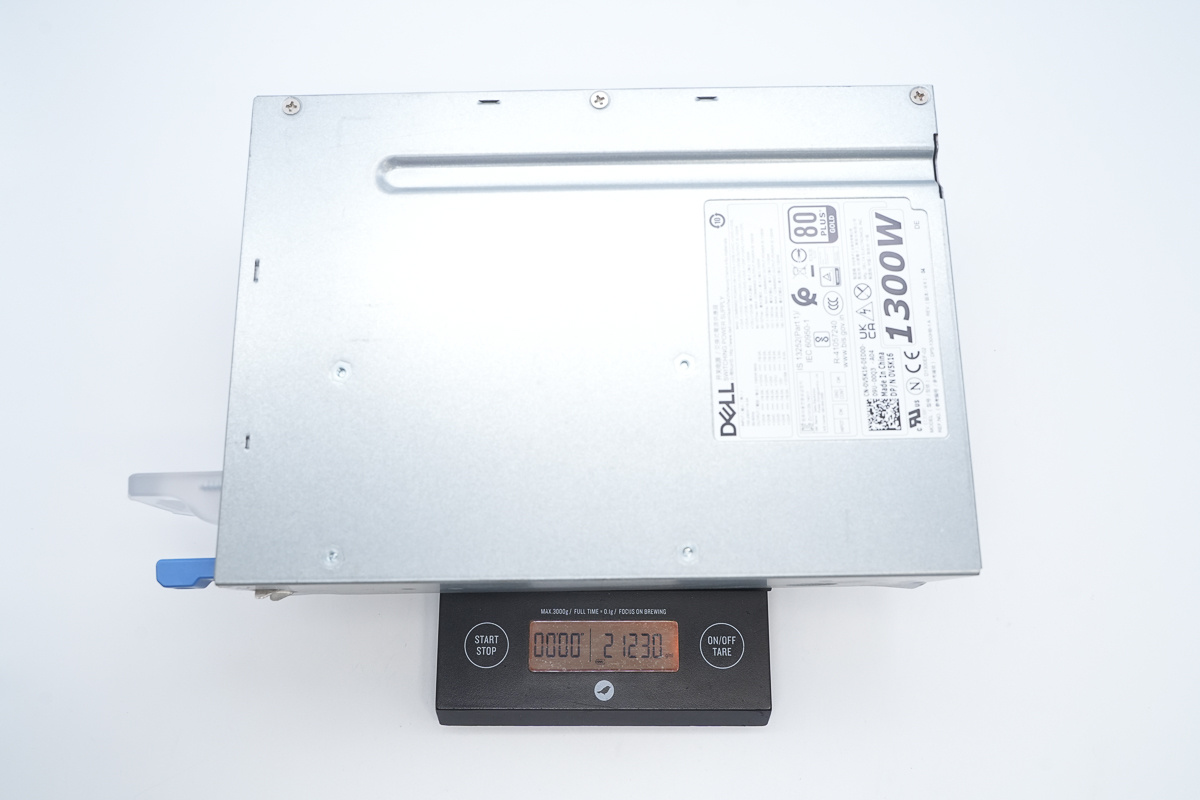
The weight is about 212g (7.478 oz).
Teardown
With the exterior overview complete, it's time to open up the DELL Workstation Power Supply and inspect its internal engineering and component layout.
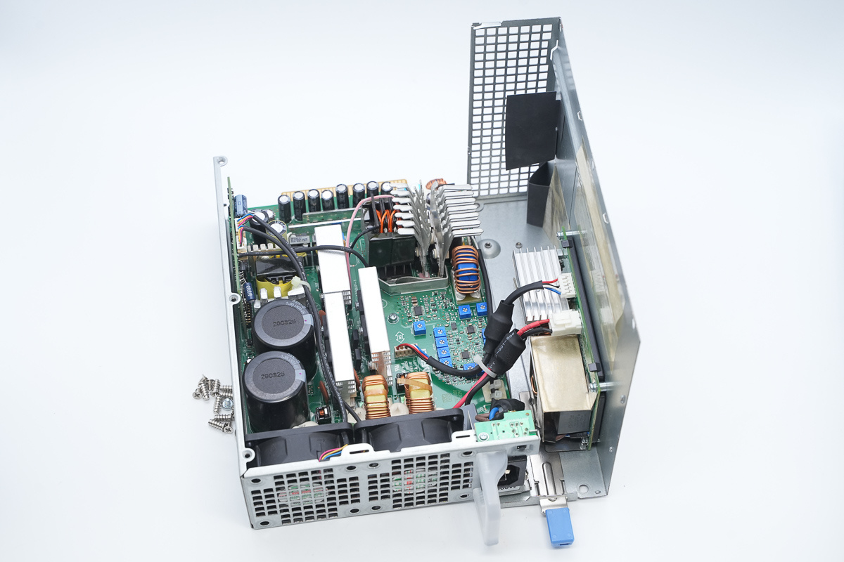
First, unscrew the fixing screws and open the power supply casing.
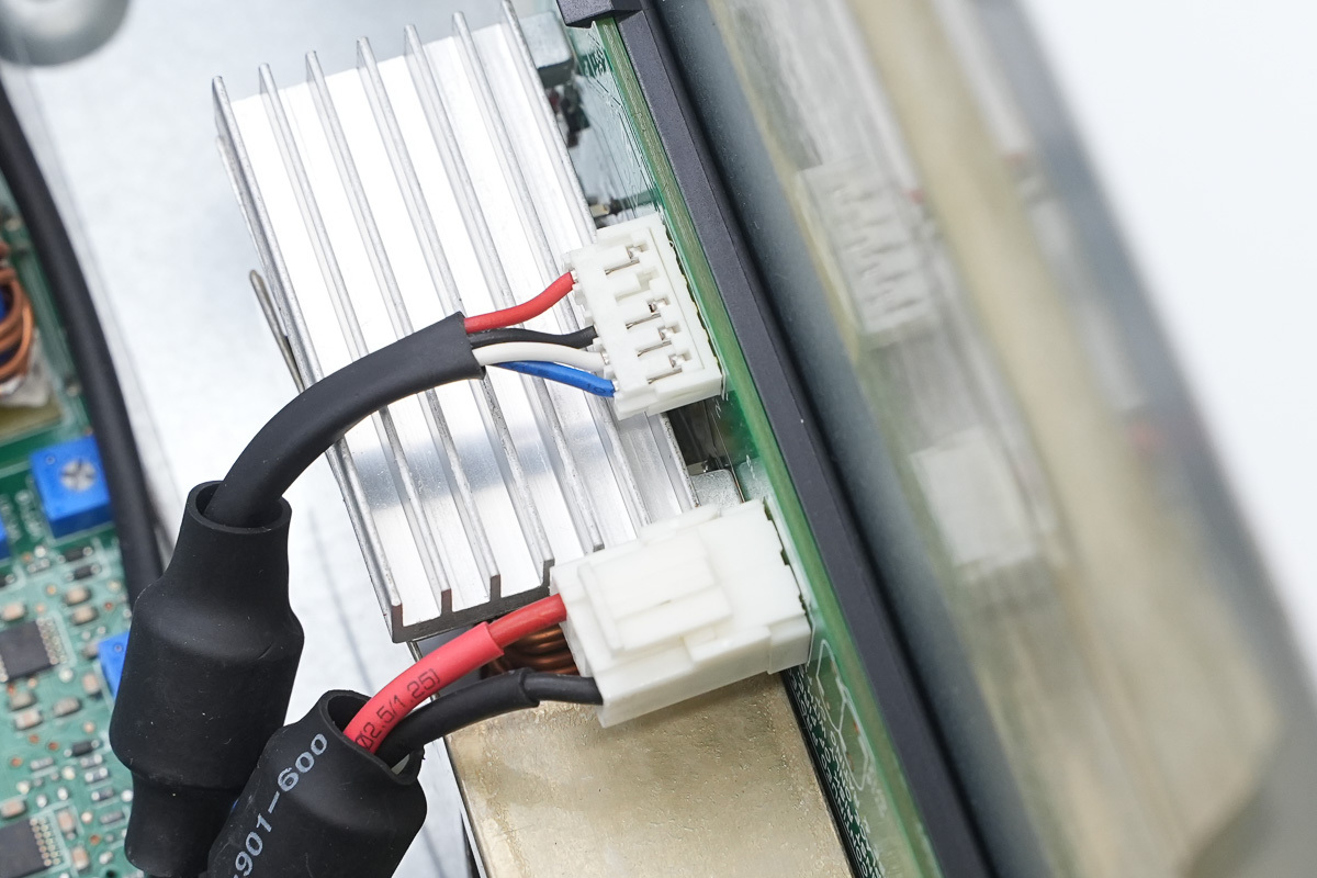
A small circuit PCB is located inside the casing, connected via wires.
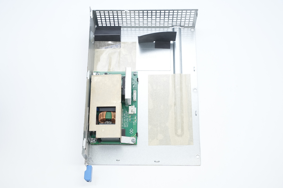
The PCB is secured with screws, and Mylar sheets are installed inside the housing for insulation.
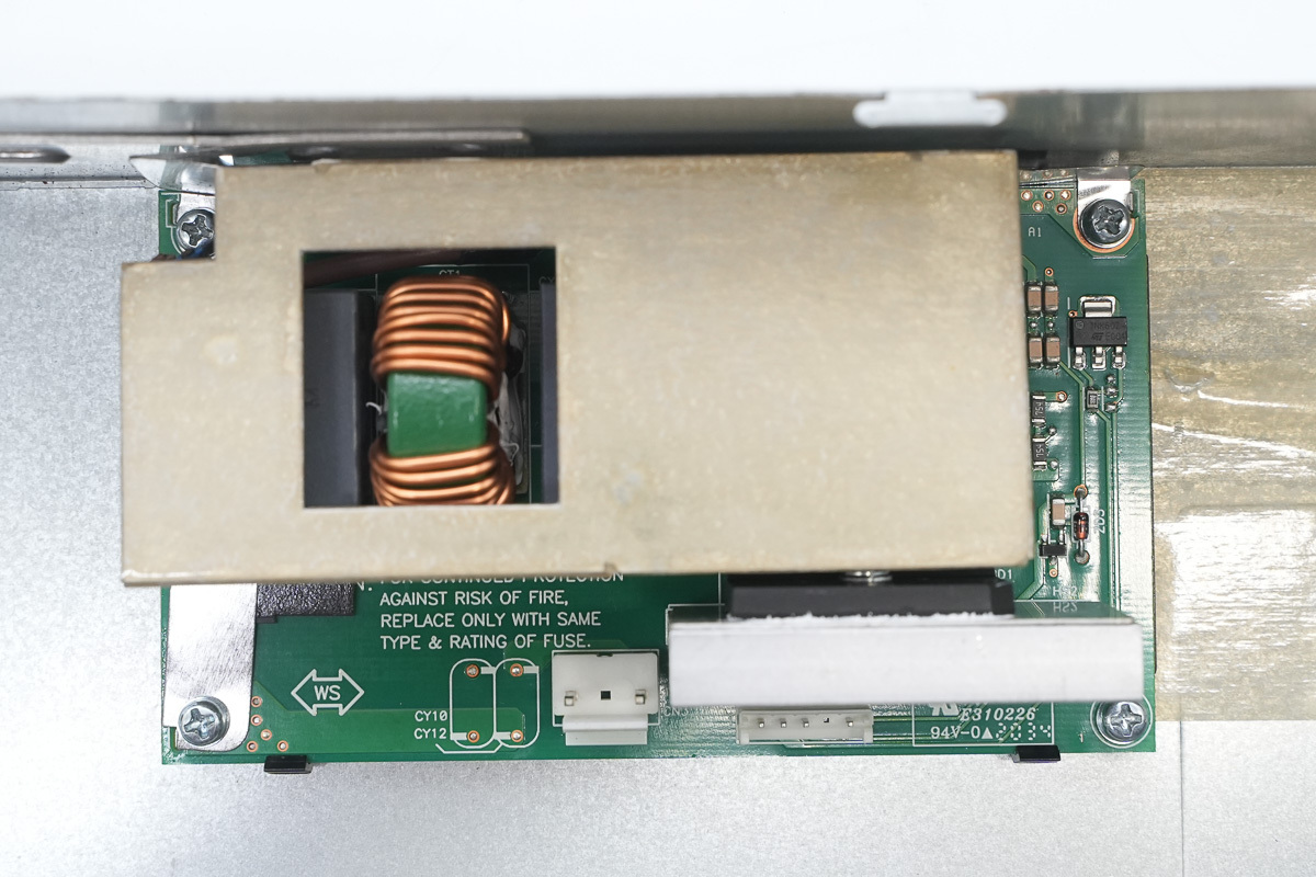
The metal framework is used to secure the PCB.
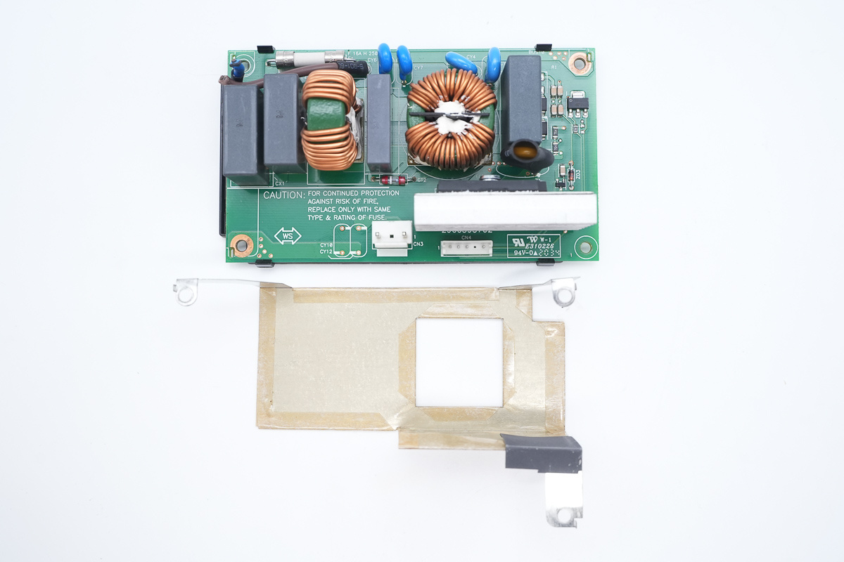
Remove the metal framework and take out the PCB.
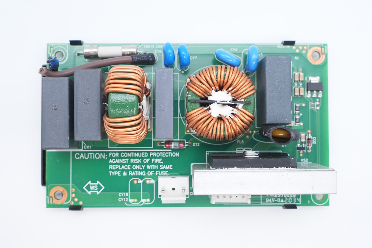
The front of the PCB is equipped with a fuse, a safety X2 cap, a common-mode choke, blue Y-caps, a varistor, and a rectifier bridge.
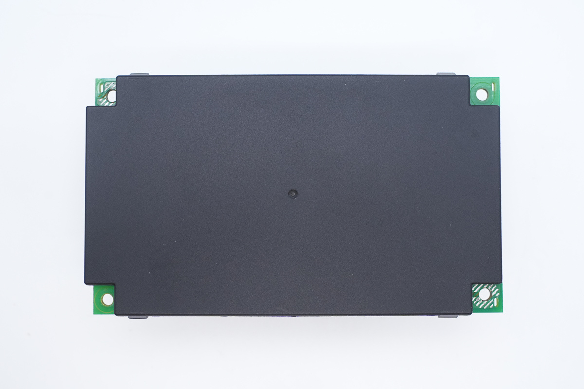
The back is covered by a plastic insulating cover.
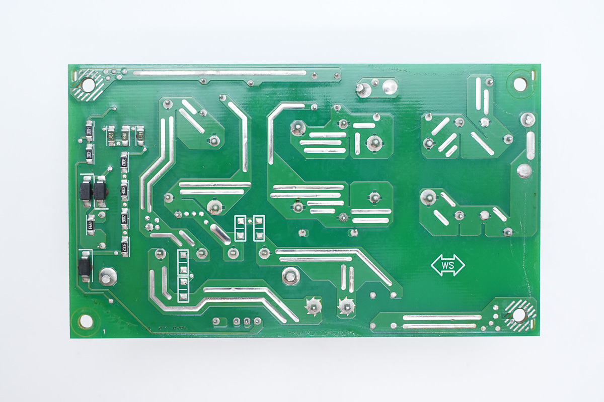
The PCB traces on the back feature exposed copper with added solder to enhance current-carrying capacity.
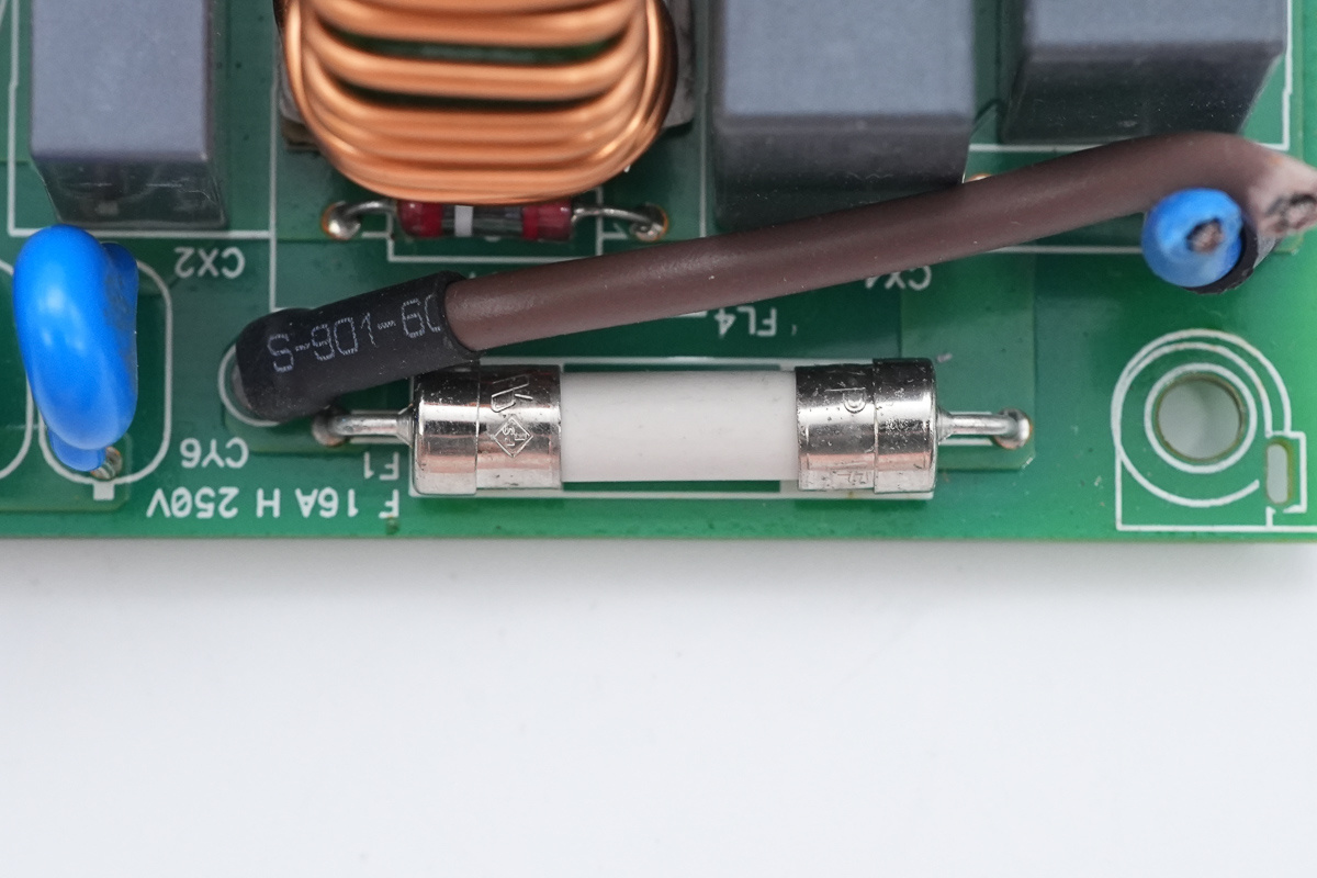
The fuse, spec 16A 250V.
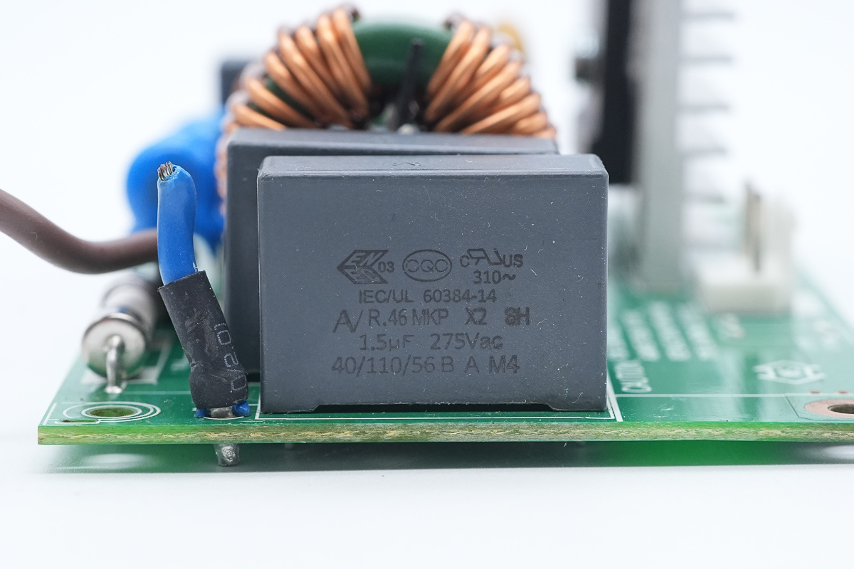
The safety X2 cap, spec 1.5μF.
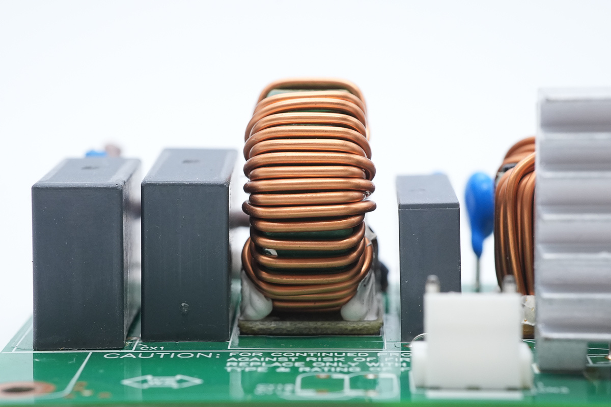
The common-mode choke is wound with enameled wire, with a Bakelite PCB at the bottom for insulation.
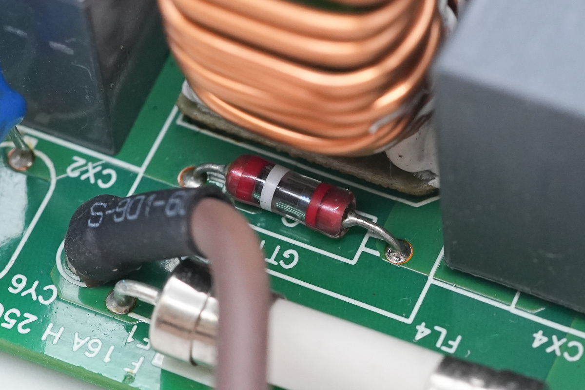
A gas discharge tube is positioned on the side of the common-mode choke.
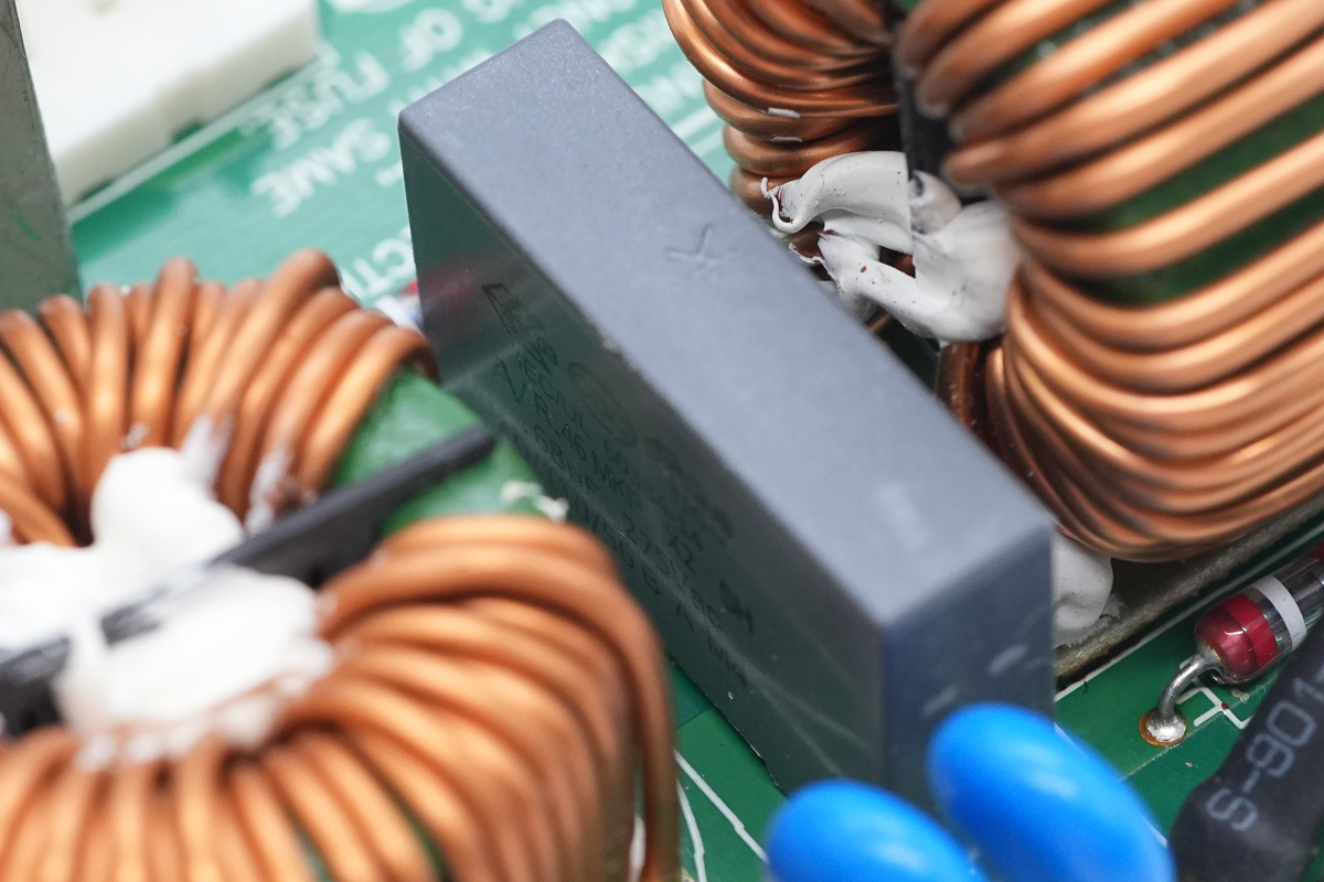
The safety X2 cap, spec 0.68μF.
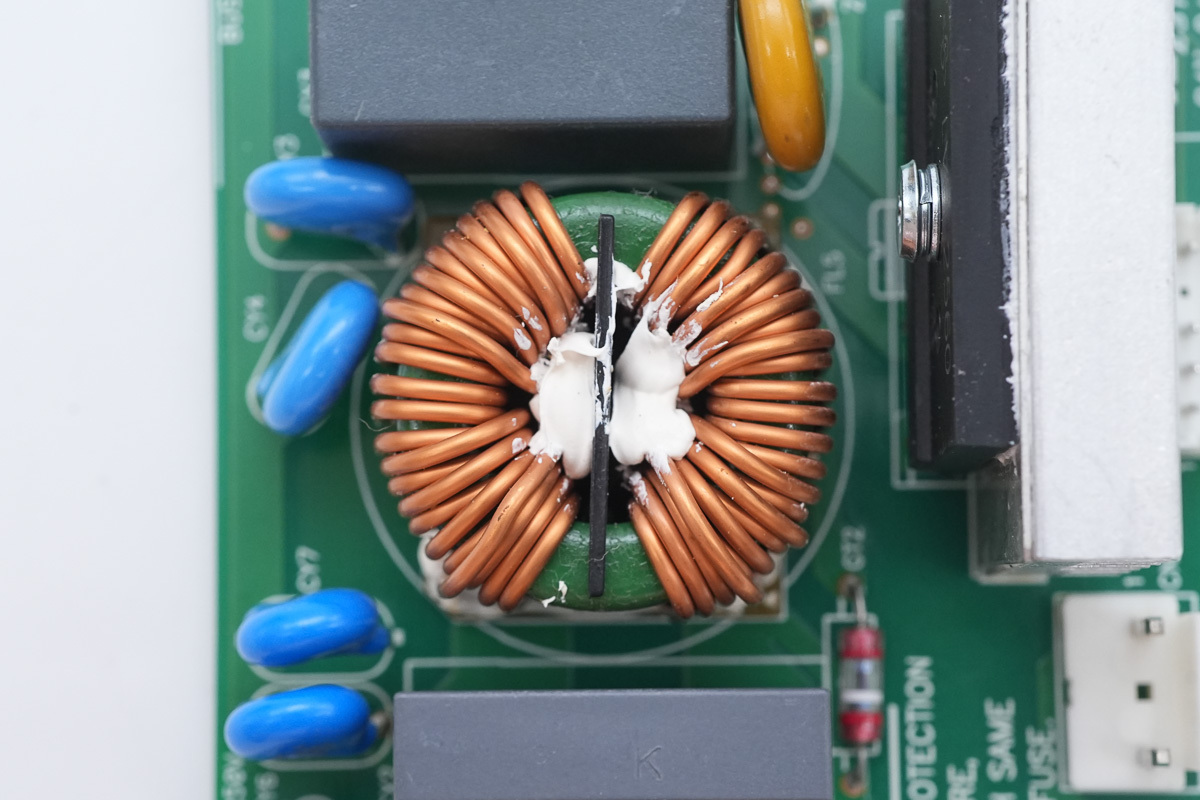
The common-mode choke is wound with enameled wire, with a Bakelite PCB at the bottom for insulation.
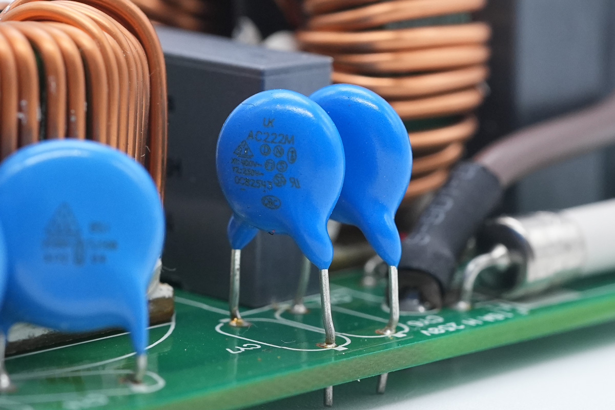
The blue Y-cap is from WTC, model AC222M.
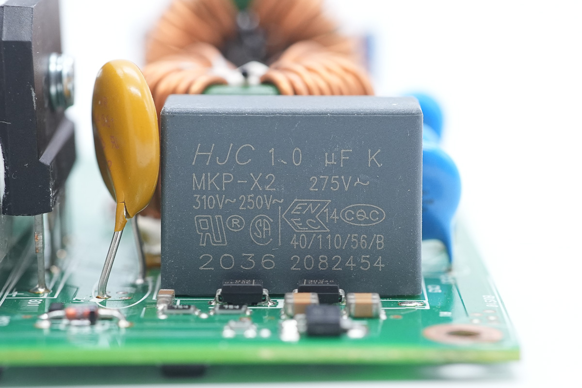
The safety X2 cap, spec 1μF.
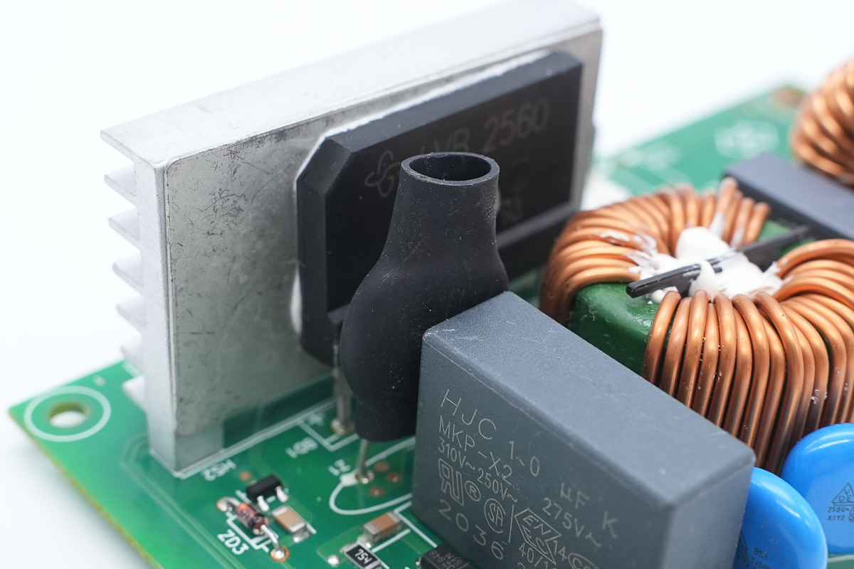
The varistor is insulated with an outer heat-shrink tubing.
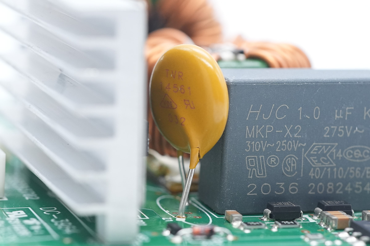
The varistor, model TVR14561, used for absorbing overvoltage surges.
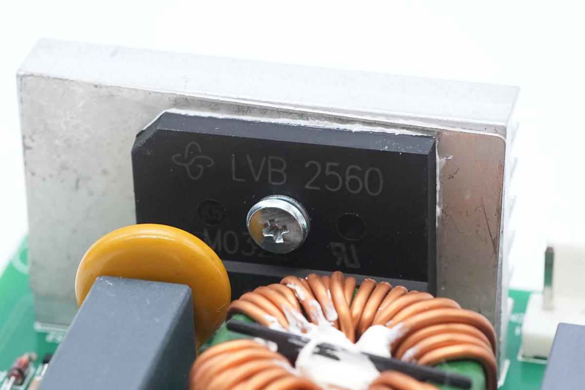
The rectifier bridge is from VISHAY, model LVB2560, which is a low forward voltage rectifier bridge rated at 600V 25A, adopting a GSIB-5S package.
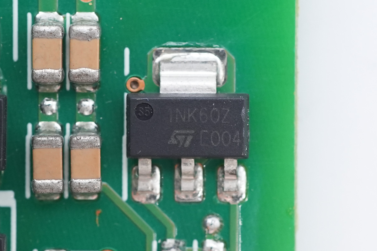
The switching MOSFET is from ST, model STN1NK60Z, NMOS, 600V and 15Ω, adopting an SOT-223 package.
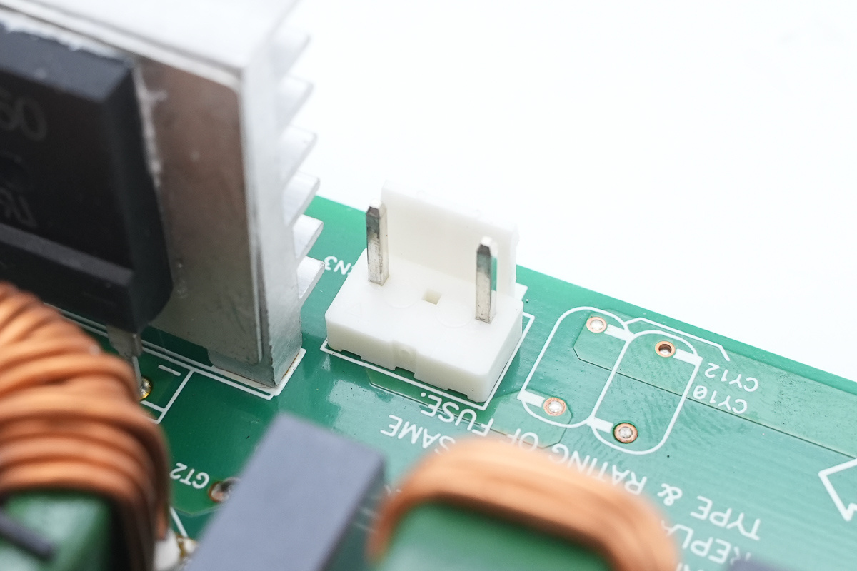
The socket connects the PCBA module.
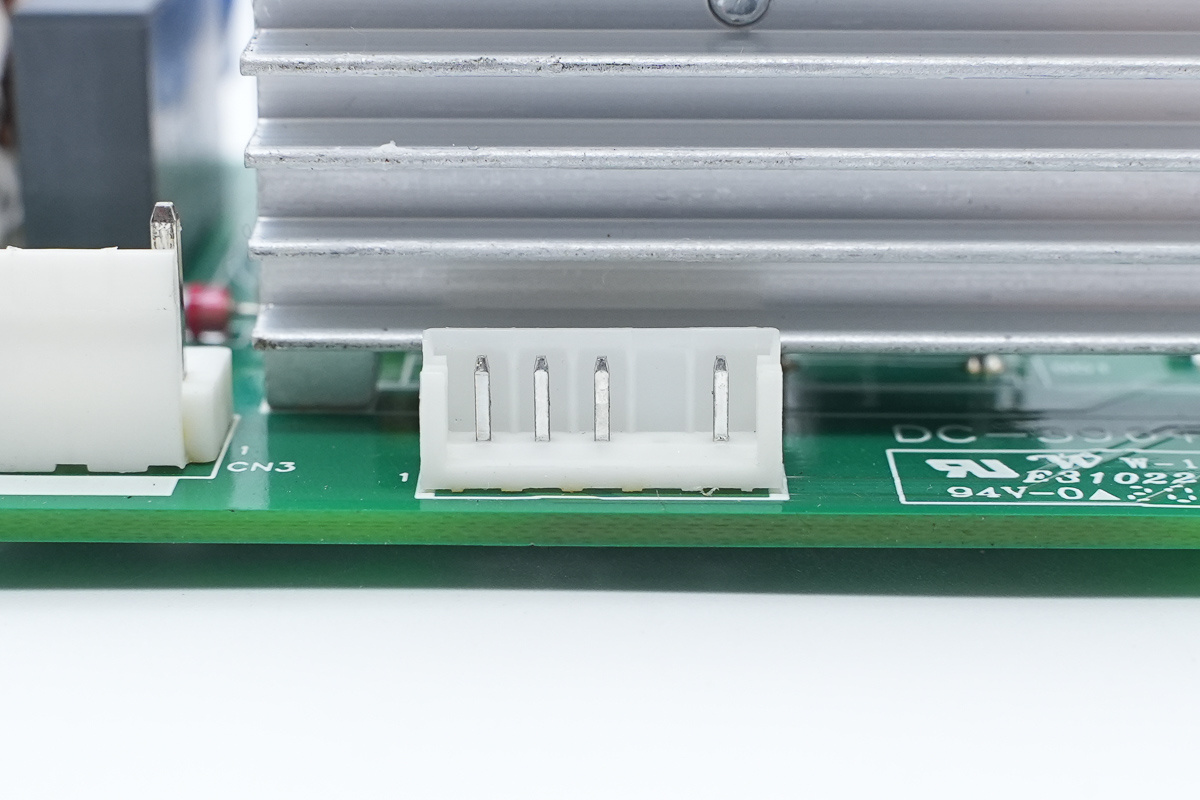
Another connection socket.
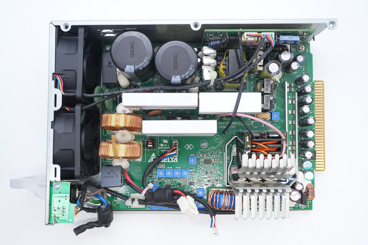
The PCBA module is secured inside the housing.
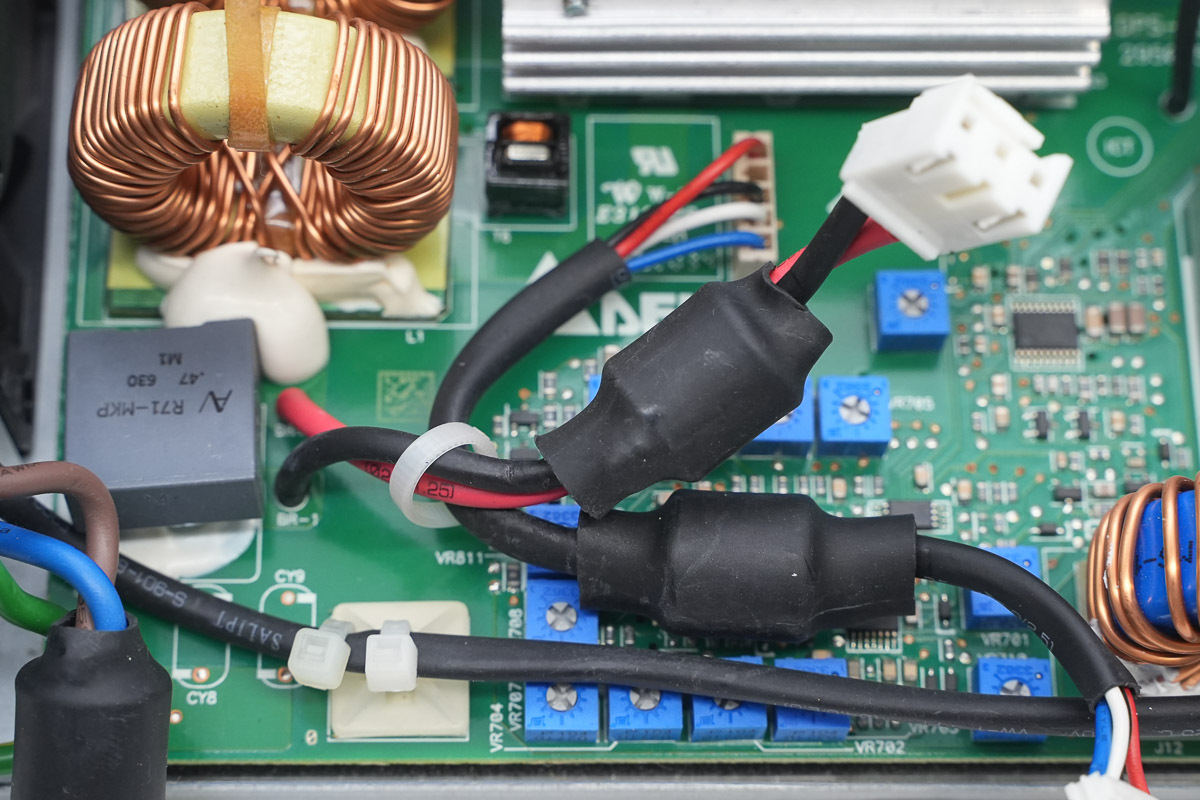
The connecting wires are sleeved with magnetic ferrite rings to suppress high-frequency interference.
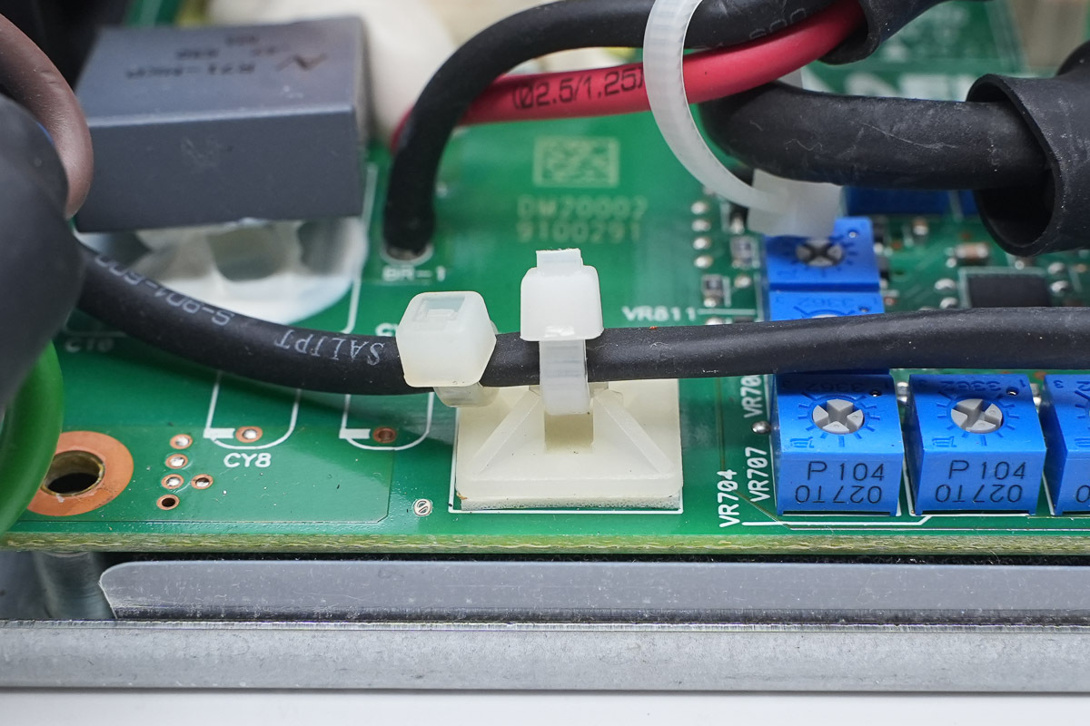
The wires are secured with cable ties.
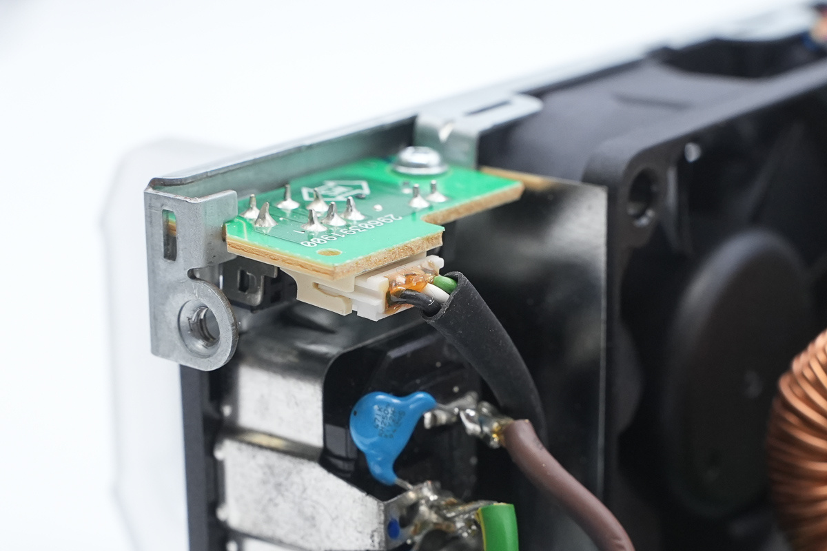
The wires connect to the LED indicator and switch PCB.
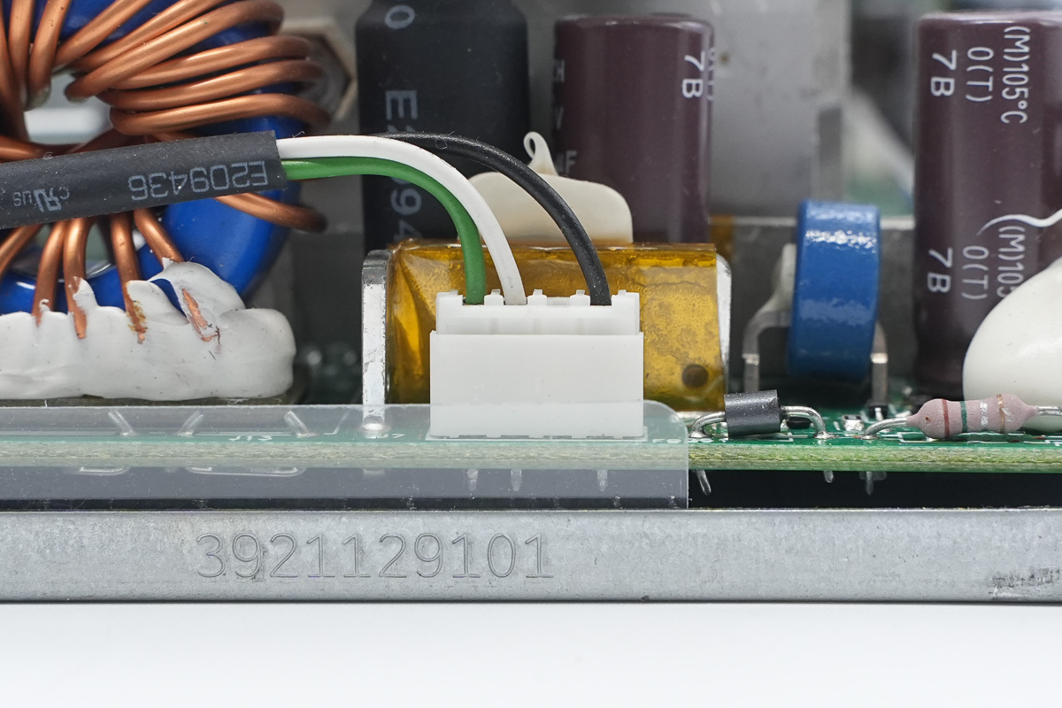
The other end is connected via a plug-in connector.
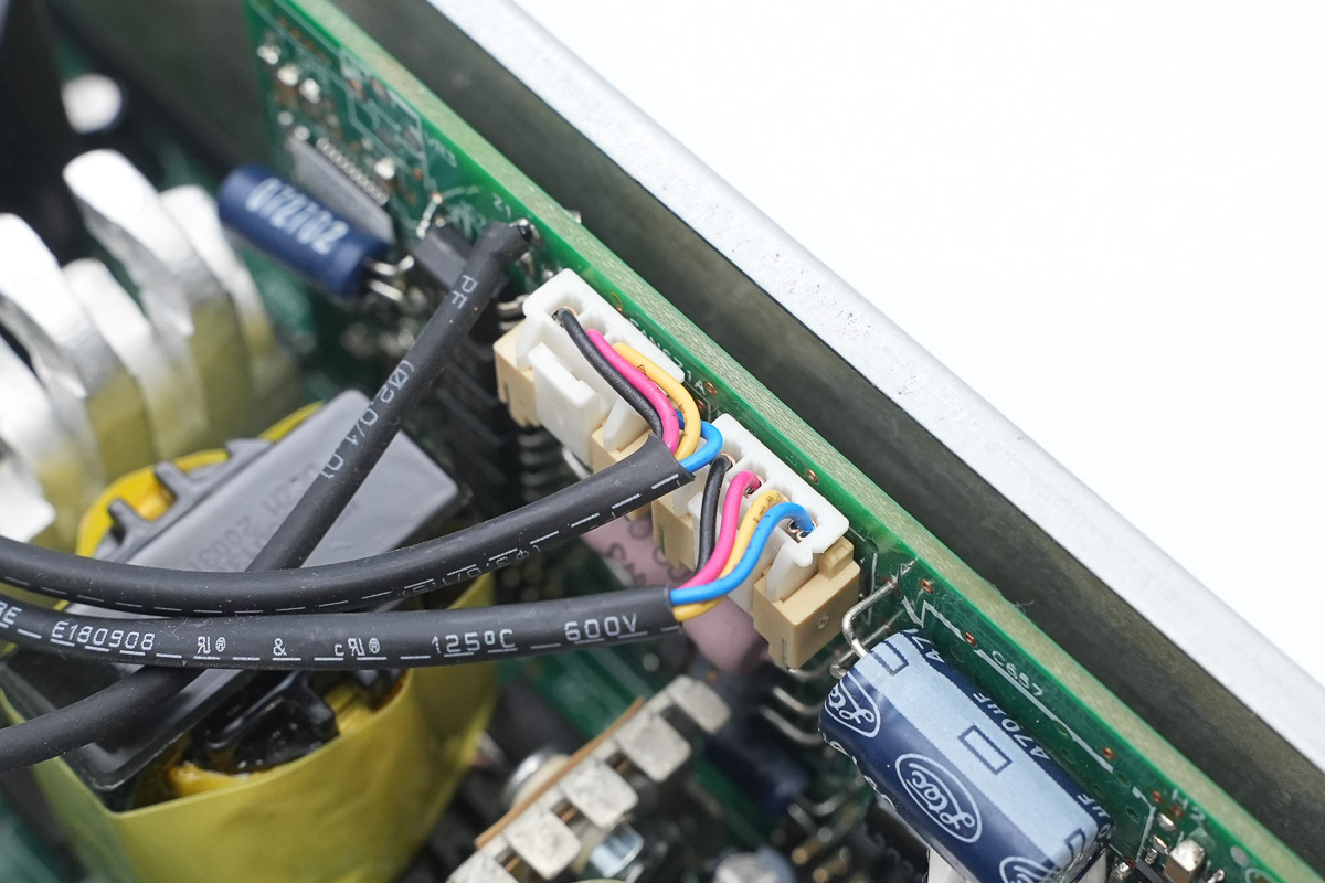
The cooling fan is connected via a plug-in connector.
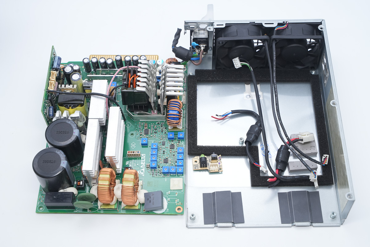
Unscrew the fixing screws and take out the PCBA module from the housing.
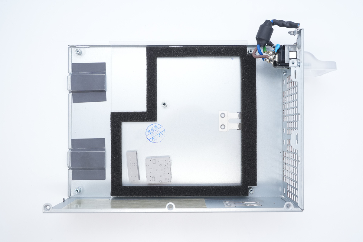
Foam is installed inside the housing to prevent foreign objects from entering, and thermal pads are affixed to assist with heat dissipation.
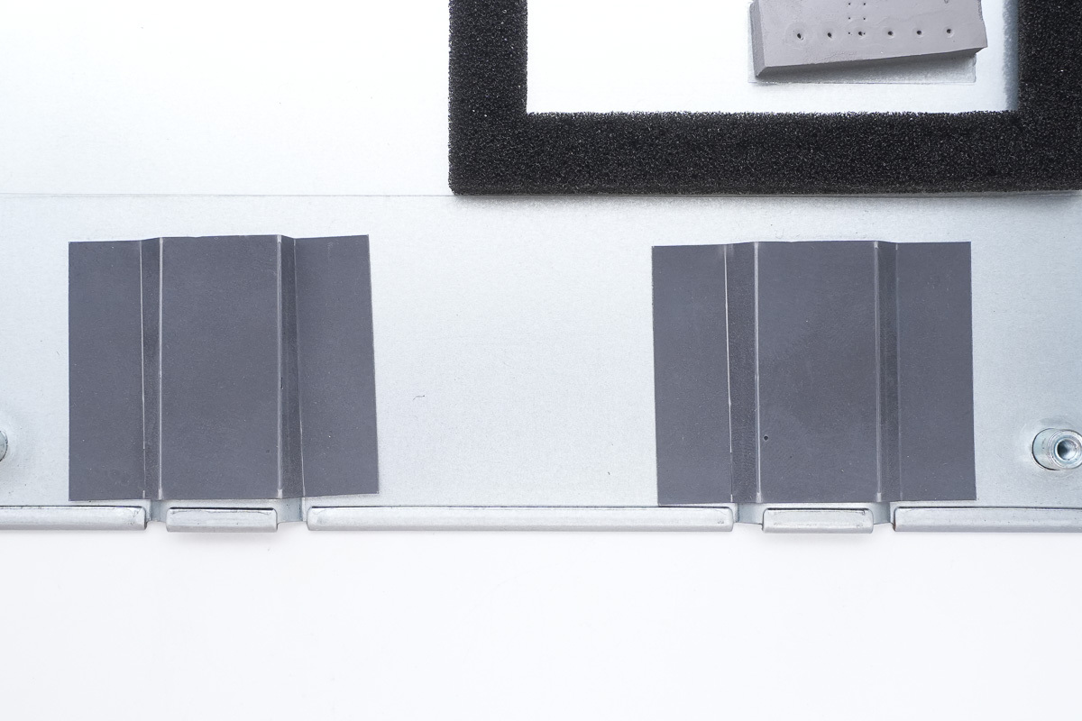
Mylar sheets are affixed to the housing protrusions for insulation.
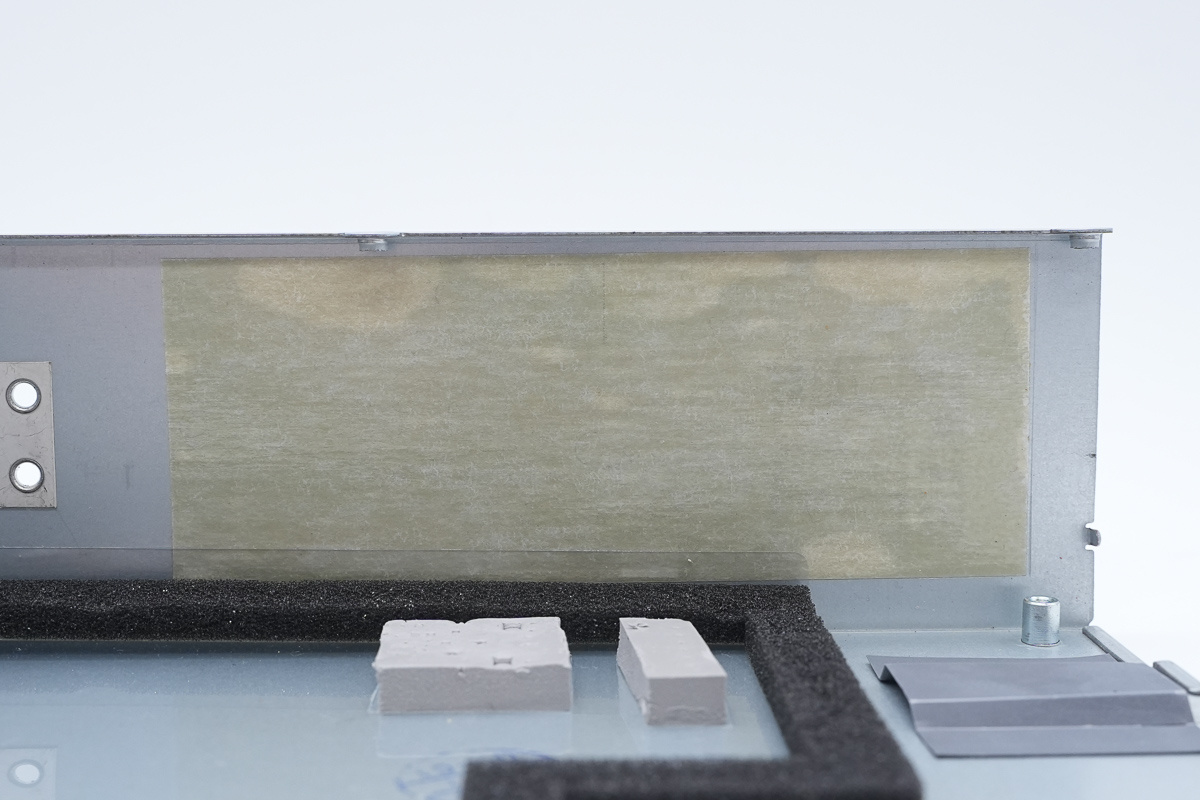
Mylar sheets are affixed to the side of the housing for insulation.
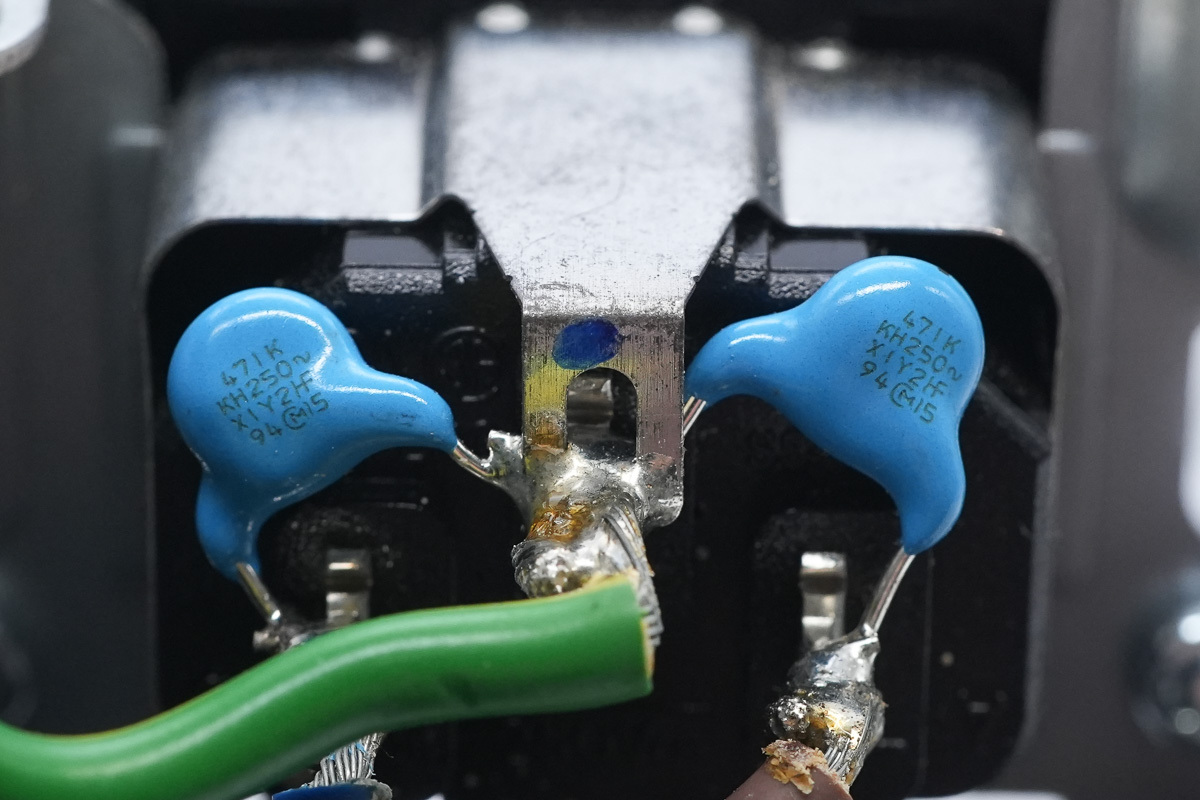
The blue Y-cap is from muRata, model 471K.
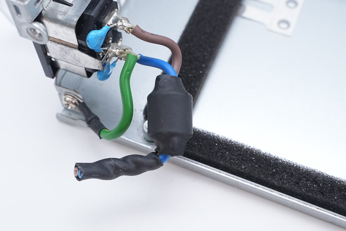
The power input line is equipped with a magnetic ring to suppress EMI.
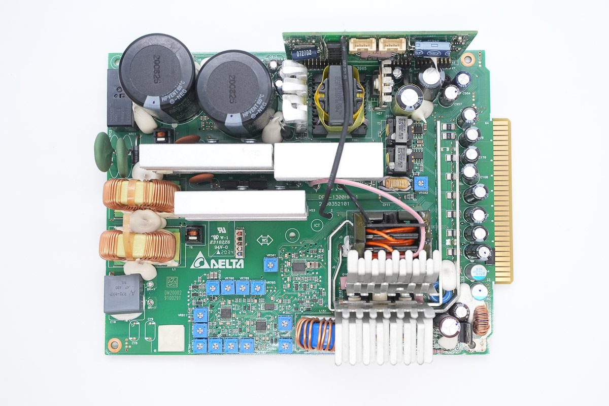
The front of the PCBA module: the lower-left corner features a film filtering cap and a PFC boost choke; the upper-left corner houses a thermistor, a relay, and high-voltage filter caps. The two heat sinks on the left cool the PFC MOSFETs and rectifier MOSFETs, while the lower section accommodates the phase-shifted full-bridge controller, adjustable resistors, and operational amplifiers. The heat sink on the right is for cooling the phase-shifted full-bridge MOSFETs.
The upper-right section contains the standby power supply chip, standby power transformer, and control PCB, while the lower-right section features the phase-shifted full-bridge transformer, synchronous rectifier MOSFETs, and filtering chokes. Current sense resistors and filtering caps are arranged along the right side.
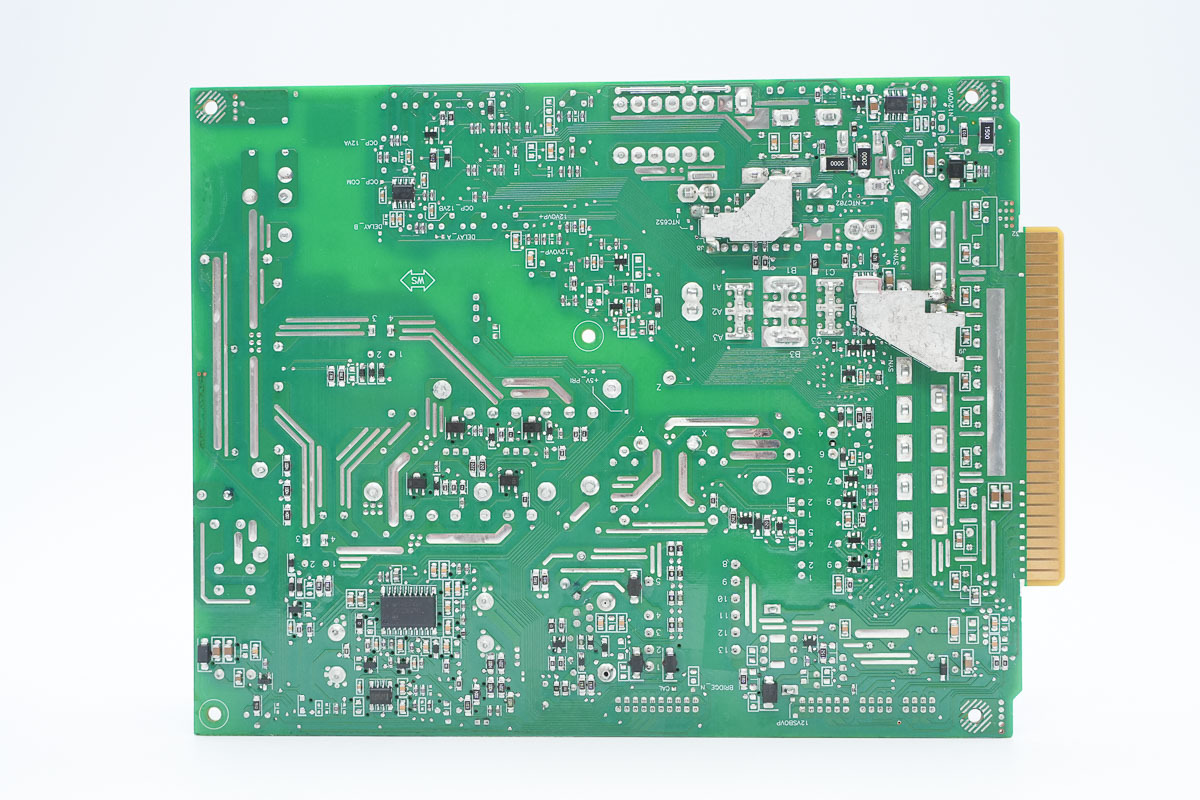
The back is populated with the PFC controller, operational amplifiers, voltage comparators, gate drivers, and power conversion chips, with copper bars welded at the output end for connections.
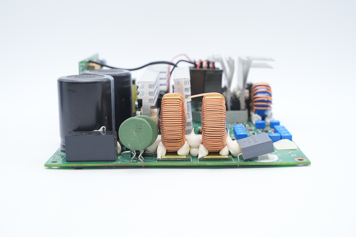
The input end of the PCBA module features a film filtering cap, PFC boost choke, thermistor, relay, and high-voltage filter caps.
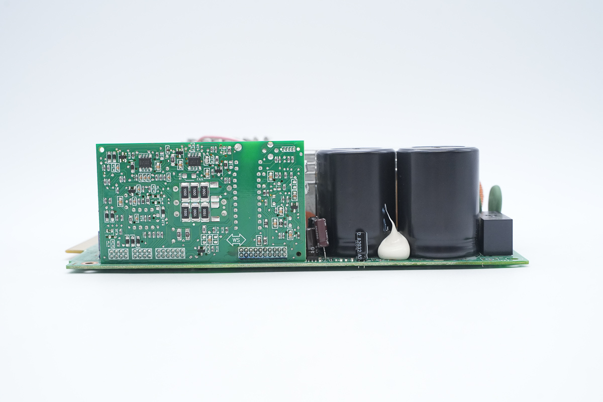
A control PCB is installed on the side.
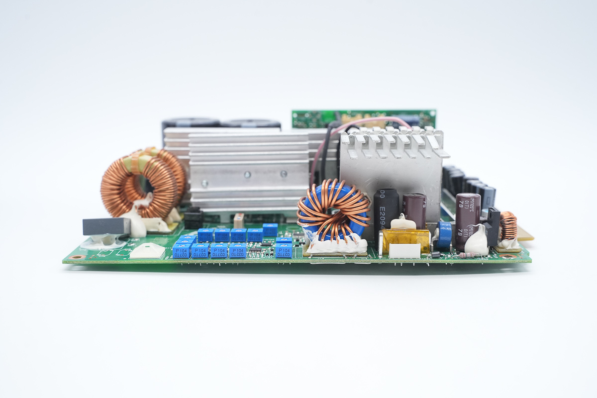
Another side is equipped with adjustable resistors, filtering chokes, and filtering caps.
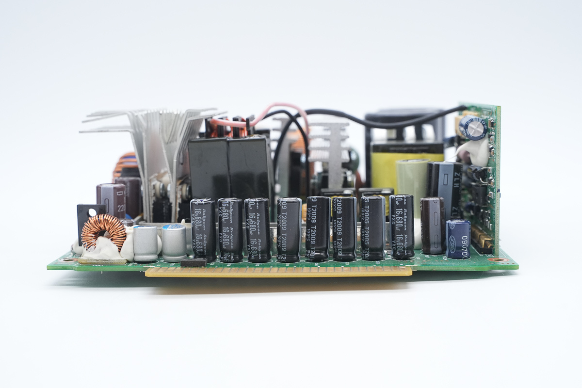
Filtering caps are positioned at the output end.
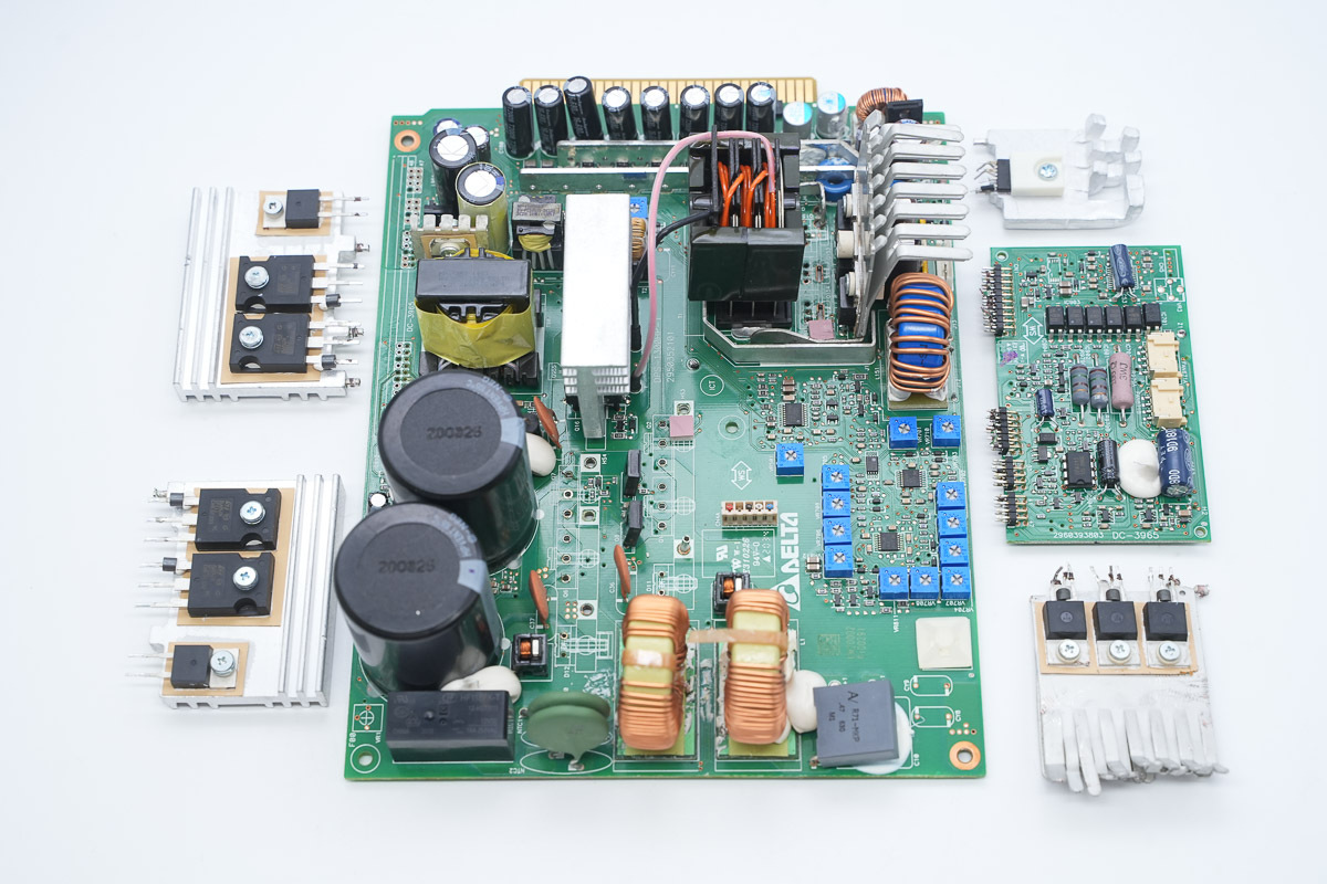
Desoldering and removing the heat sinks and control PCB to continue the teardown.
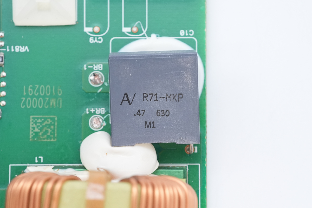
The input end film cap, spec 0.47μF630V.
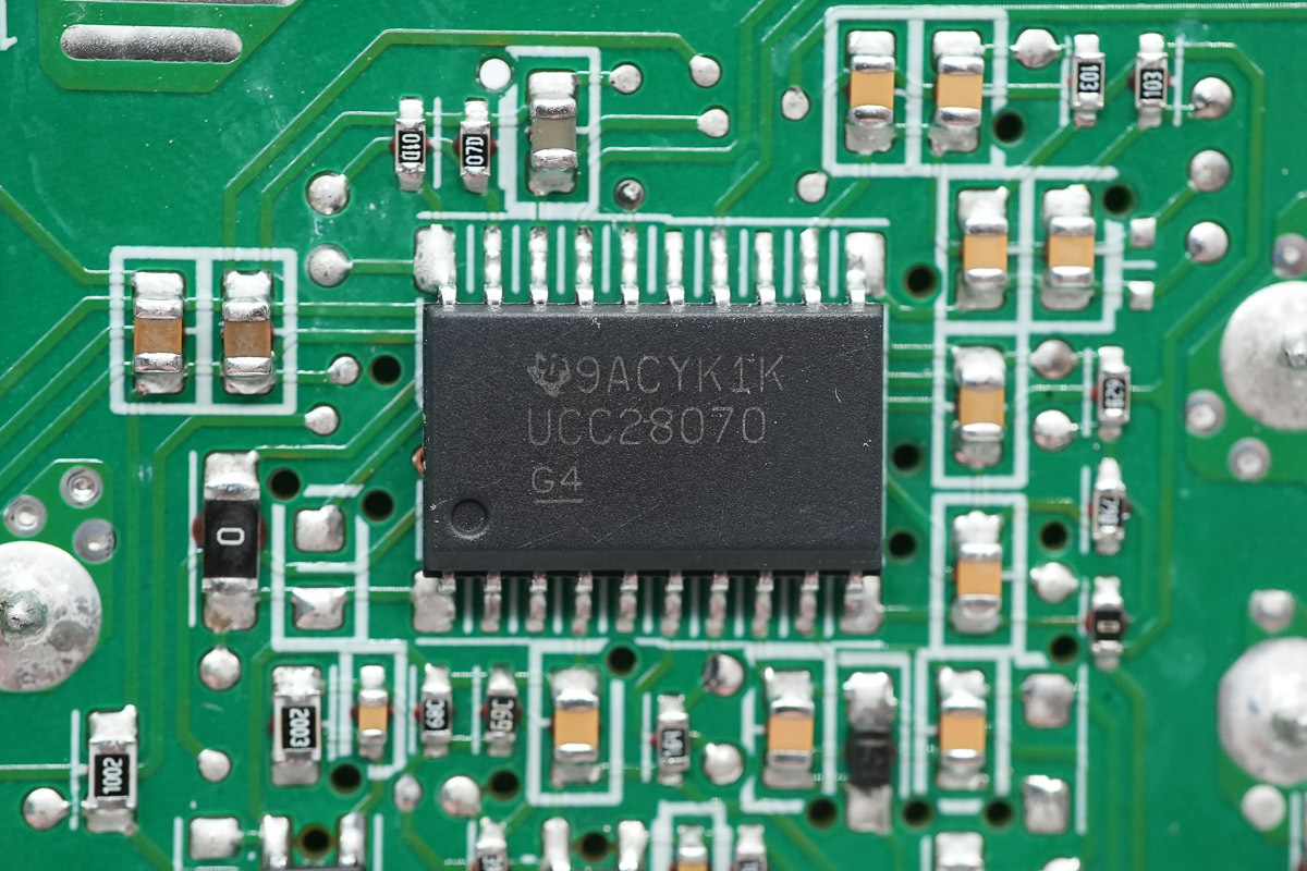
The PFC controller is from TI, model UCC28070, which is an interleaved continuous conduction mode PFC controller supporting a switching frequency of 30–300 kHz. It features programmable maximum duty cycle clamping, programmable soft-start and peak current limiting, and provides UVLO, output OVP, and open-loop detection. It supports IGBT, Si, and GaN devices, and adopts an SOIC-20 package.
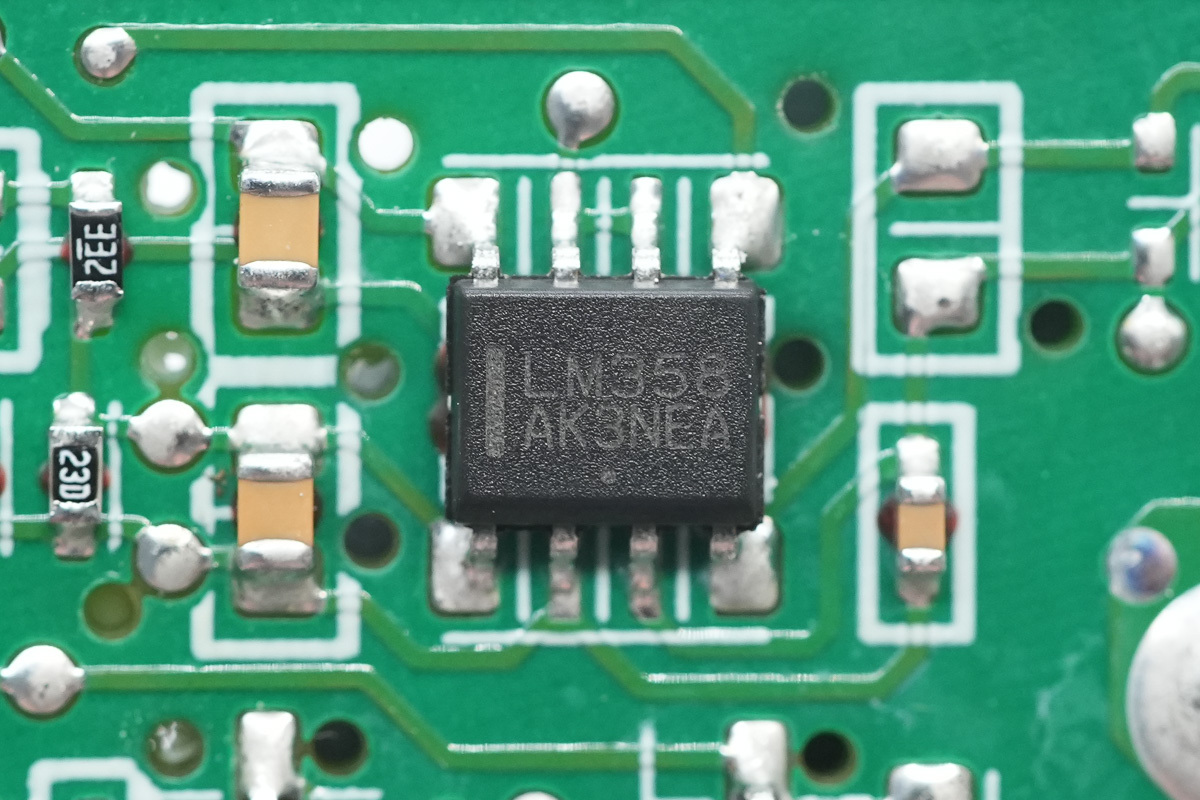
The operational amplifier is from ST, model LM358, which is a low-power dual operational amplifier adopting an SO-8 package.
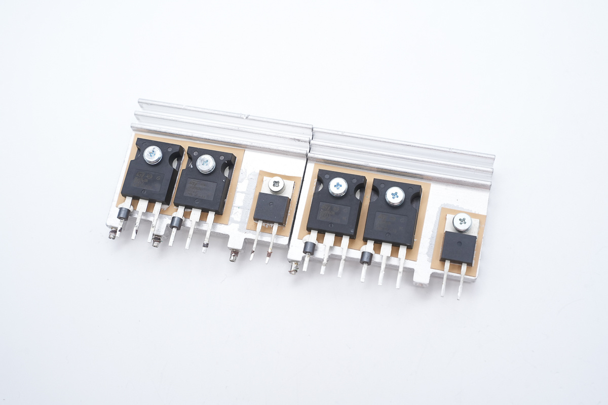
The PFC MOSFETs and PFC rectifier MOSFETs are secured on a heat sink.
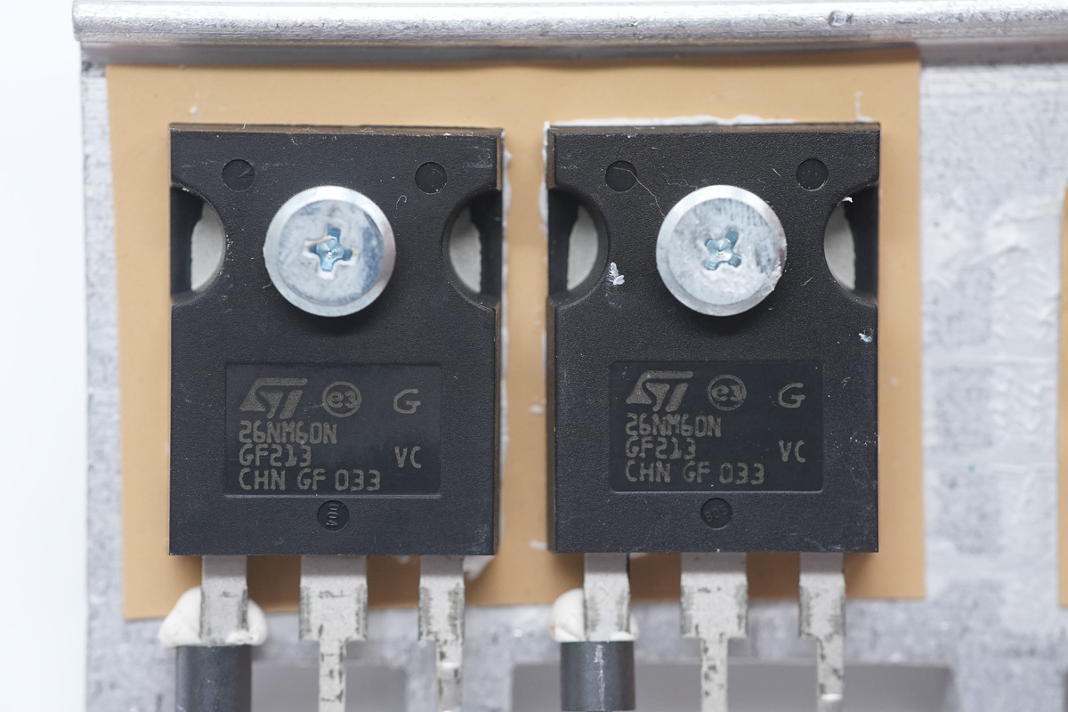
The PFC MOSFET is from ST, model STW26NM60N, NMOS, 600V and 135mΩ, adopting a TO-247 package.
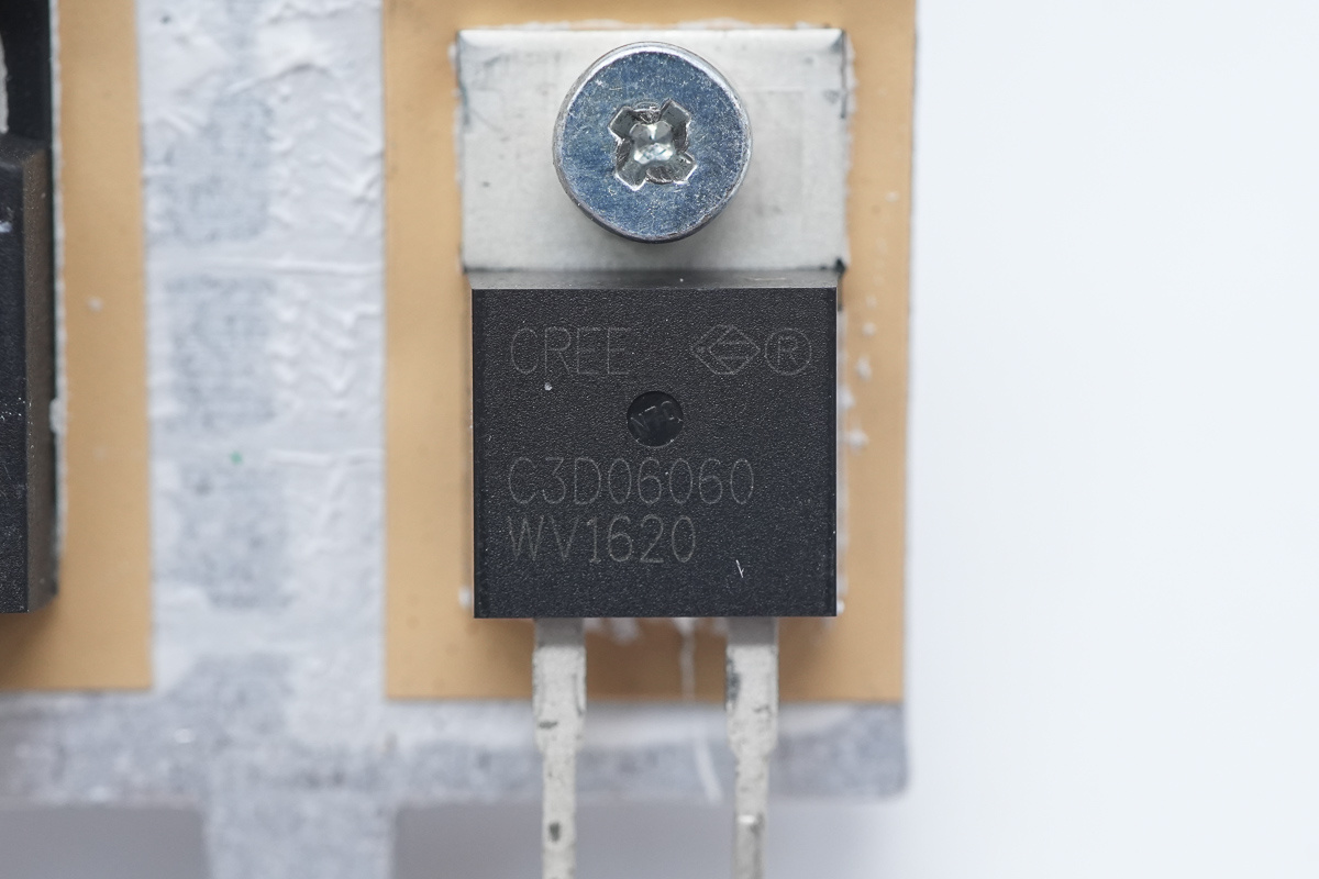
The PFC rectifier MOSFET is from Wolfspeed, model C3D06060A, which is a SiC Schottky diode rated at 600V 6A, adopting a TO-220-2 package.
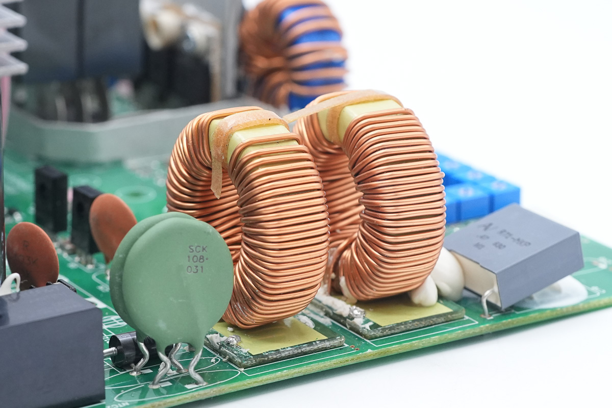
The PFC choke is wound with enameled wire, with a bakelite board at the bottom for insulation.
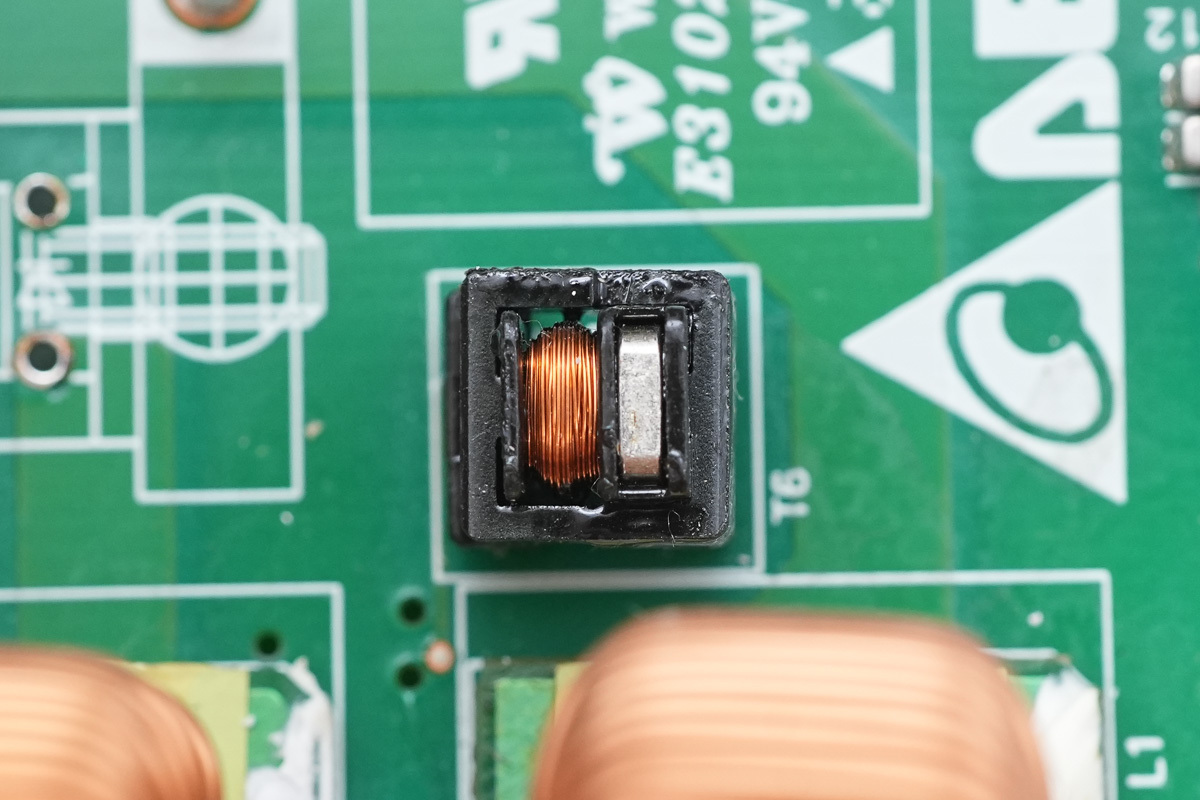
The current transformer is used for detecting choke current.
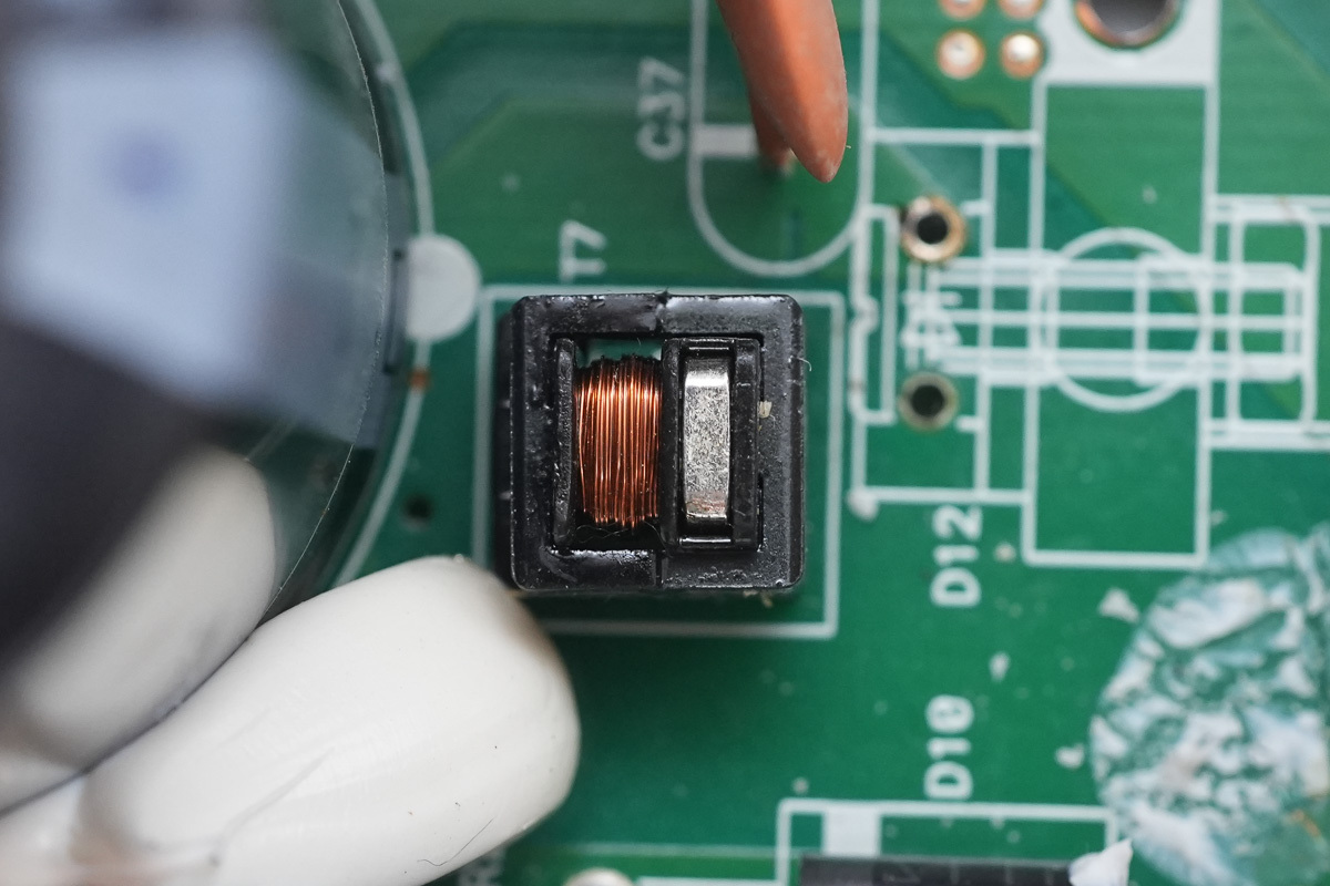
Another current transformer.
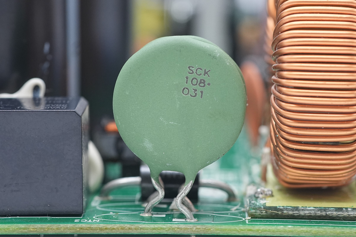
The thermistors, marked SCK108, are used in a two-piece series configuration to suppress inrush current during power-up.
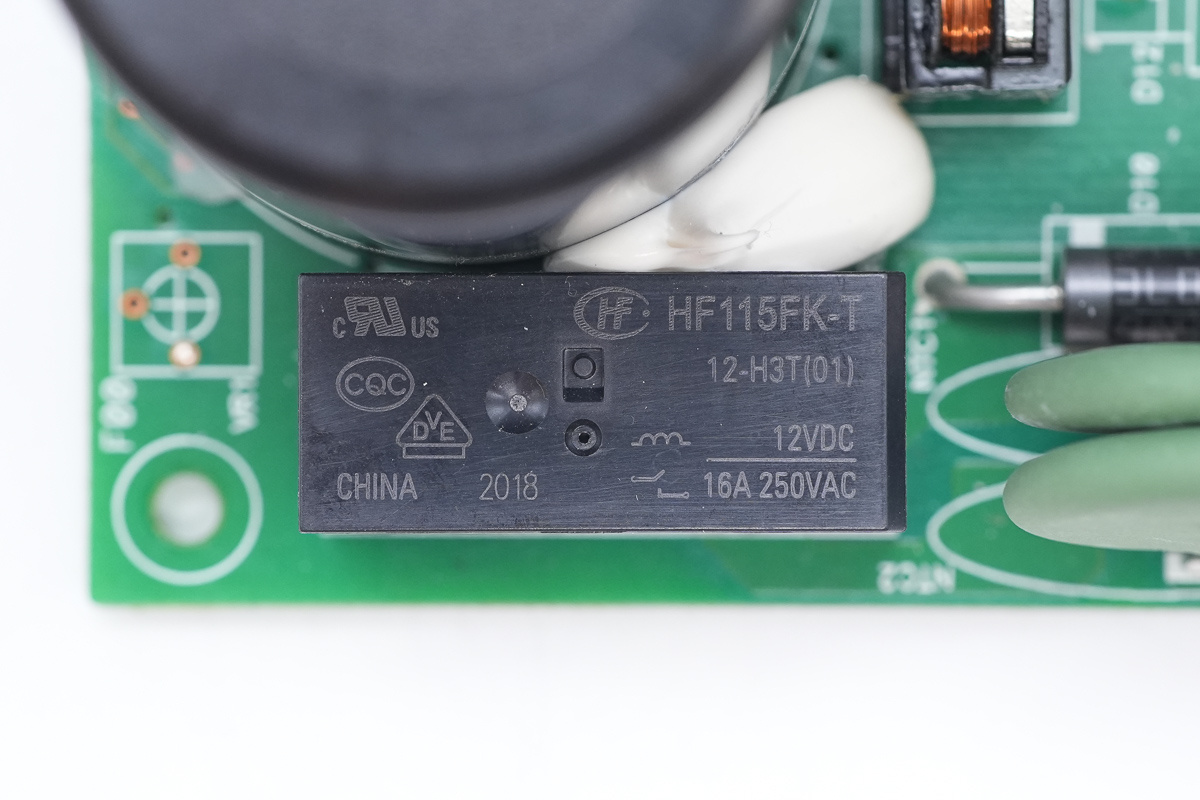
The relay is from HONGFA, model HF115FK-T/12-H3T, which is a miniature high-power DC relay with one set of normally open contacts, featuring a 16A contact switching capacity and a 12V coil voltage.
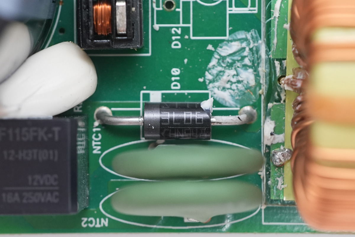
The bypass diode is from ST, model STTH3L06, spec 600V 3A, adopting a DO-201AD package.
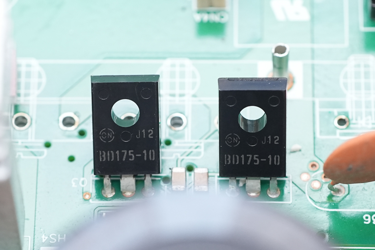
The two MOSFETs are from onsemi, model BD17510STU, which are NPN transistors rated at 45V 3A, adopting a TO-126-3 package.
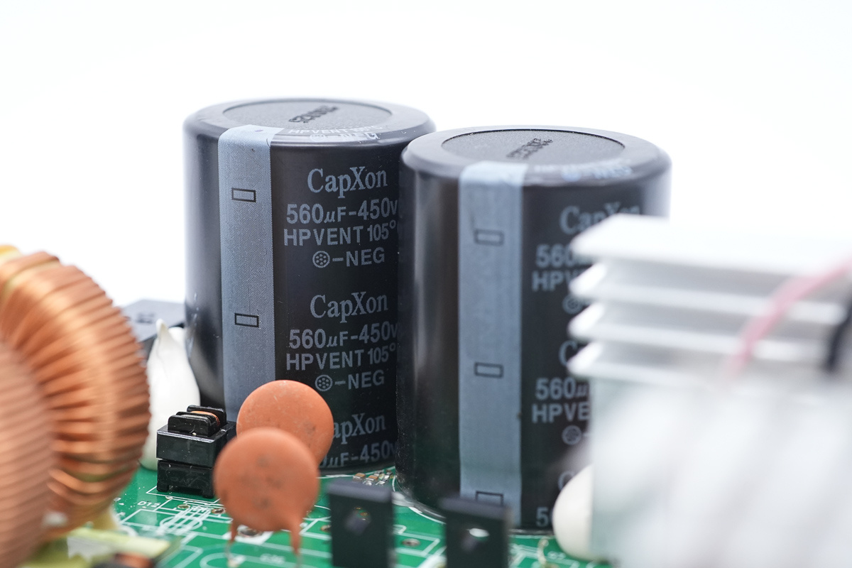
The high-voltage filter caps are from CapXon, spec 560μF 450V, connected in parallel using two pieces.
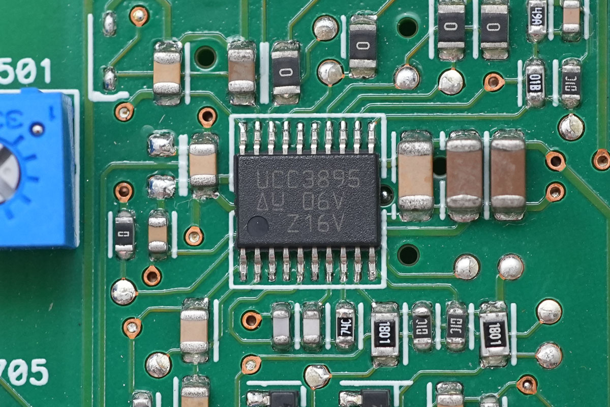
The phase-shifted full-bridge controller is from TI, model UCC3895, supporting constant-frequency PWM and resonant ZVS, as well as voltage-mode and current-mode control. It features enhanced control logic, adaptive delay setting, and shutdown functionality, adopting a TSSOP-20 package.
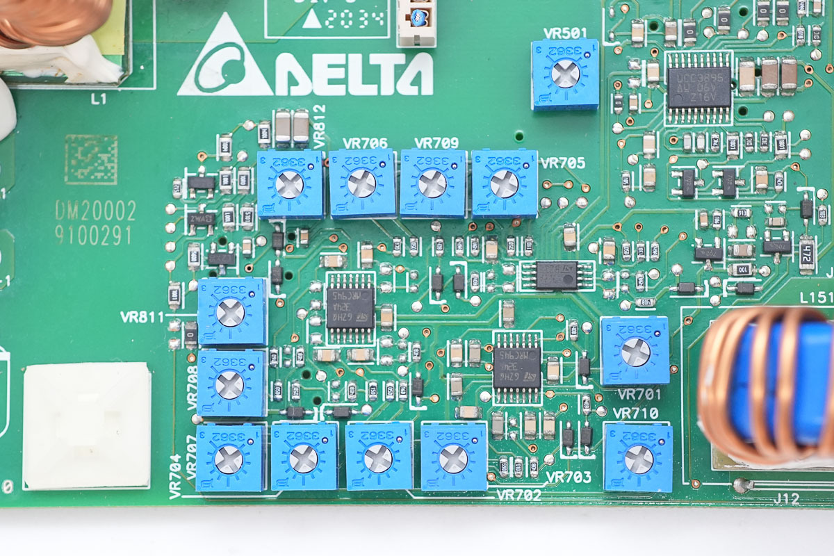
There are adjustable potentiometers and operational amplifiers.
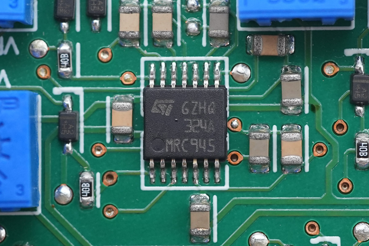
The operational amplifier is from ST, model LM324A, which is a low-power, low-input-bias-current quad operational amplifier adopting a TSSOP-14 package.
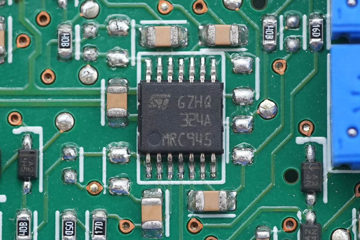
Another one shares the same model.
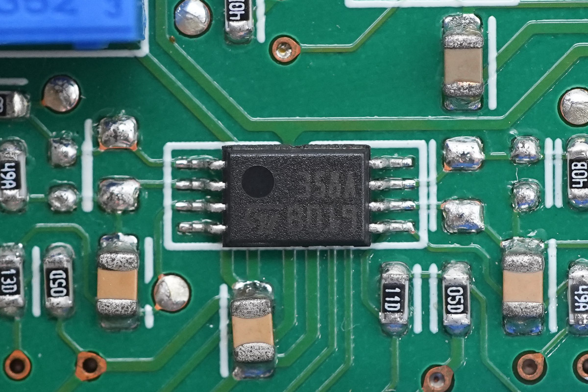
The operational amplifier is from ST, model LM358A, which is a low-power dual operational amplifier adopting a MiniSO-8 package.
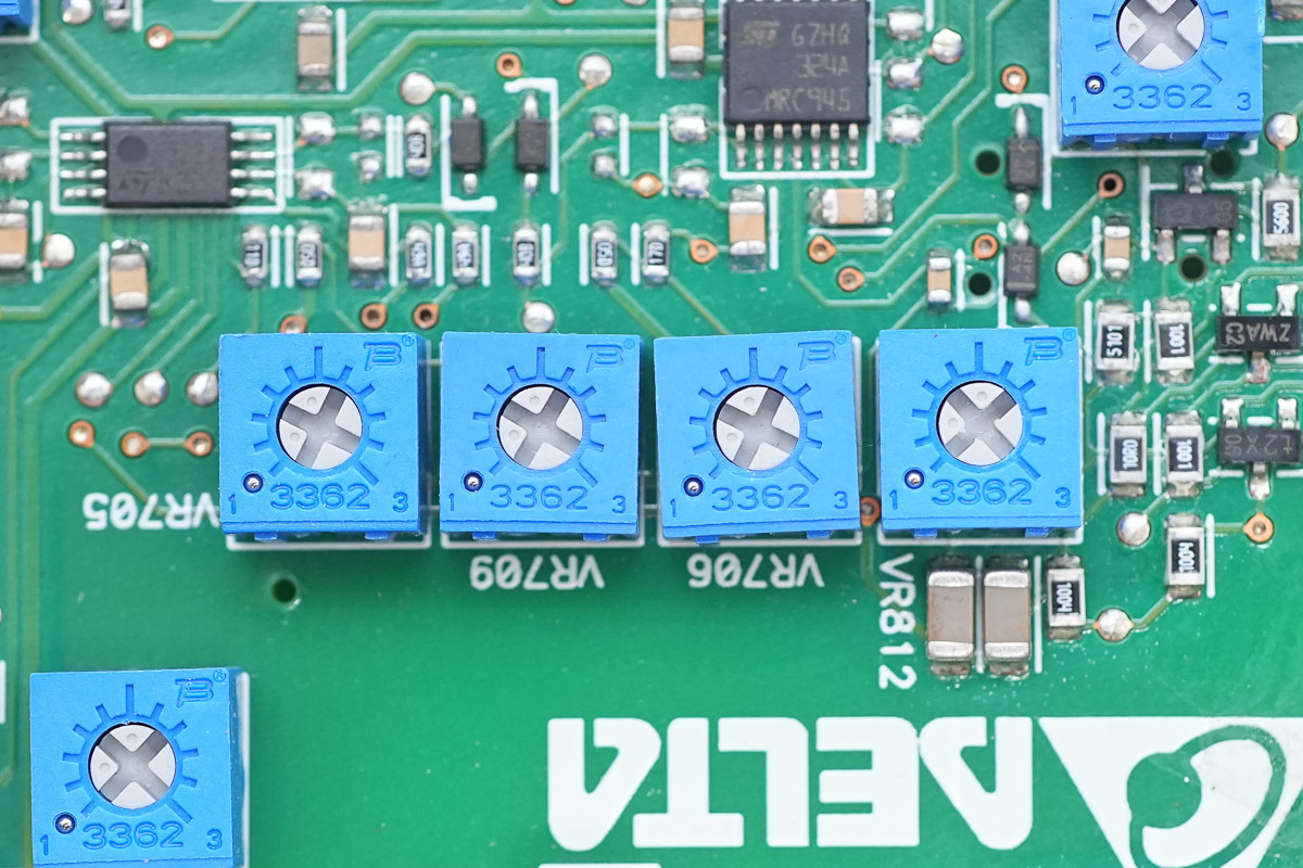
The blue adjustable potentiometers.
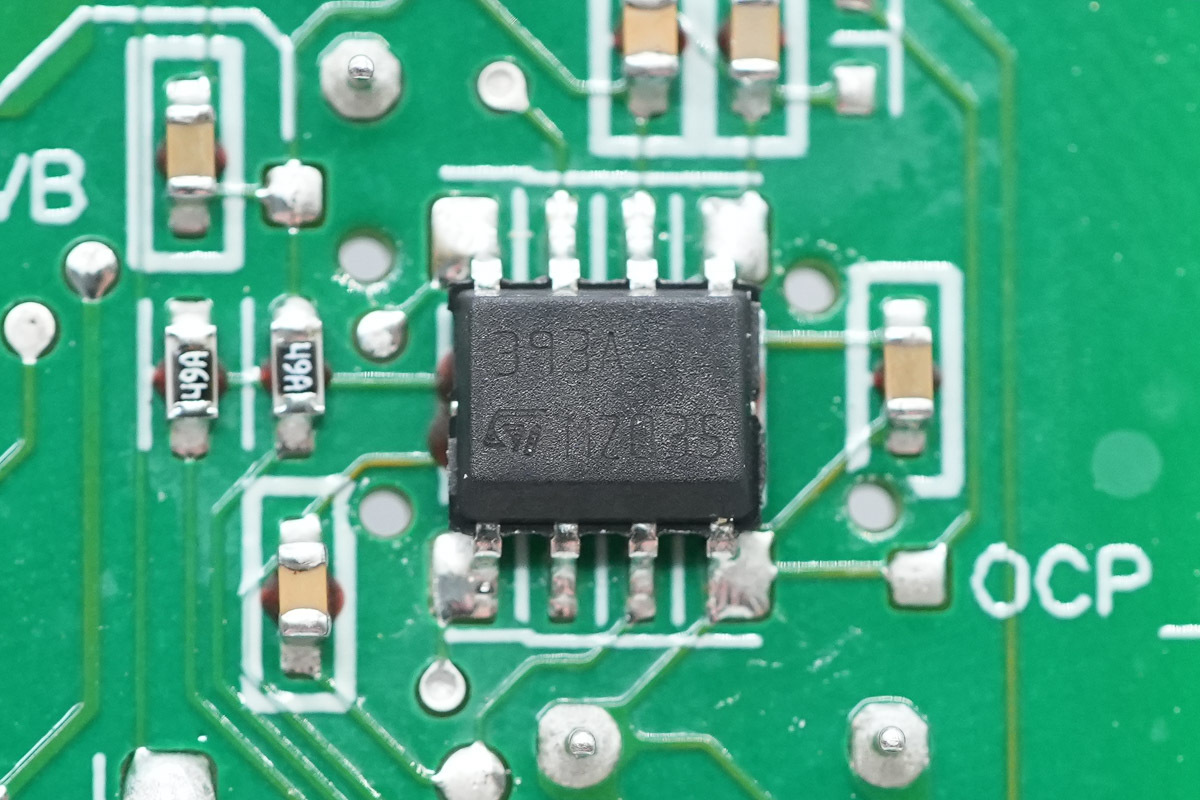
The voltage comparator is from ST, model LM393A, which is a low-power dual voltage comparator adopting an SO-8 package.
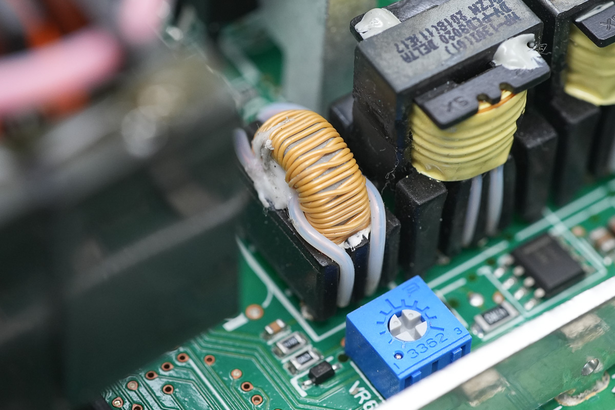
The current transformer is wound with insulated wire.
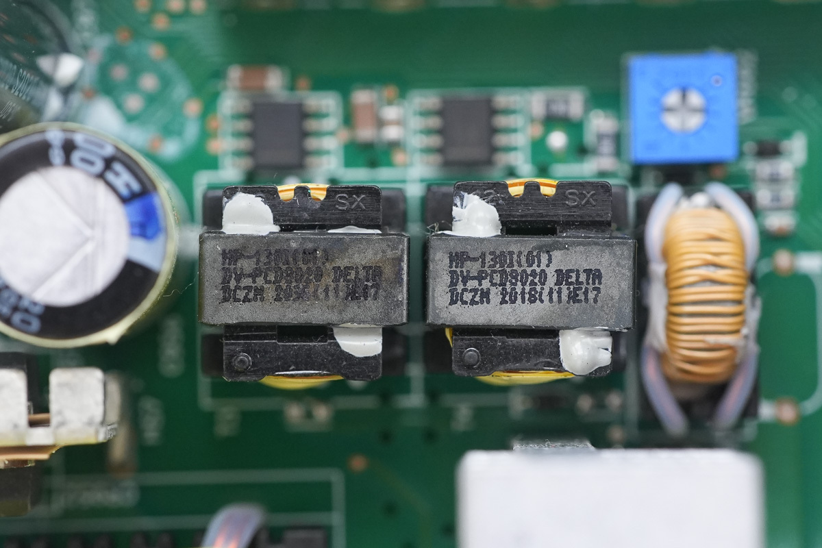
Two transformers are used for isolation driving.
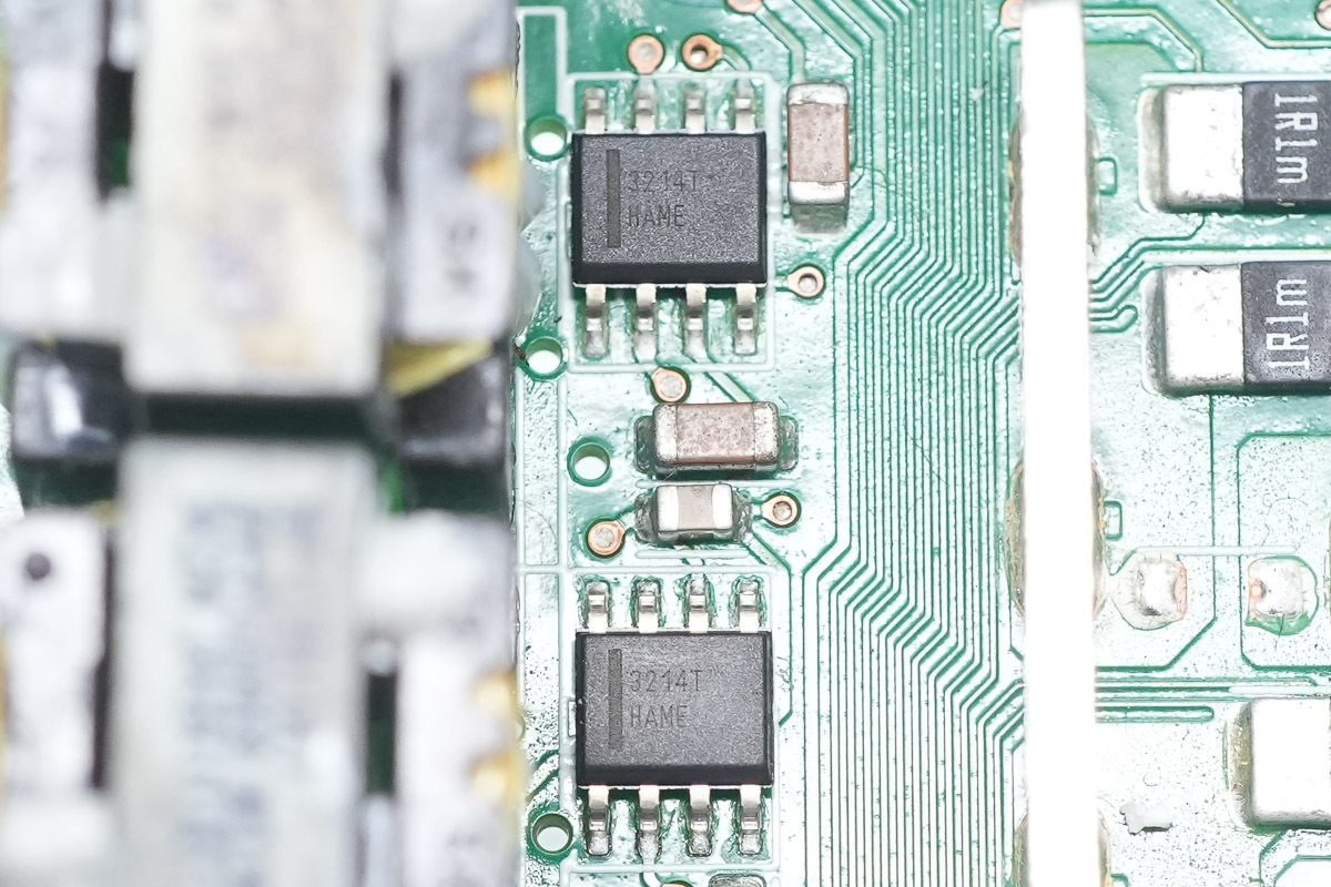
The driver is from onsemi, model FAN3214T, which is a dual-channel low-side high-speed driver with 4A output current capability, adopting an SOIC-8 package.
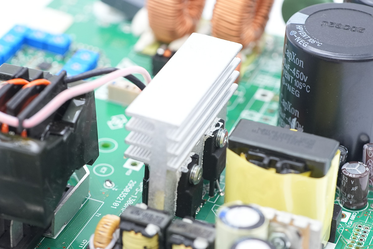
The phase-shifted full-bridge MOSFET is secured on a heat sink.
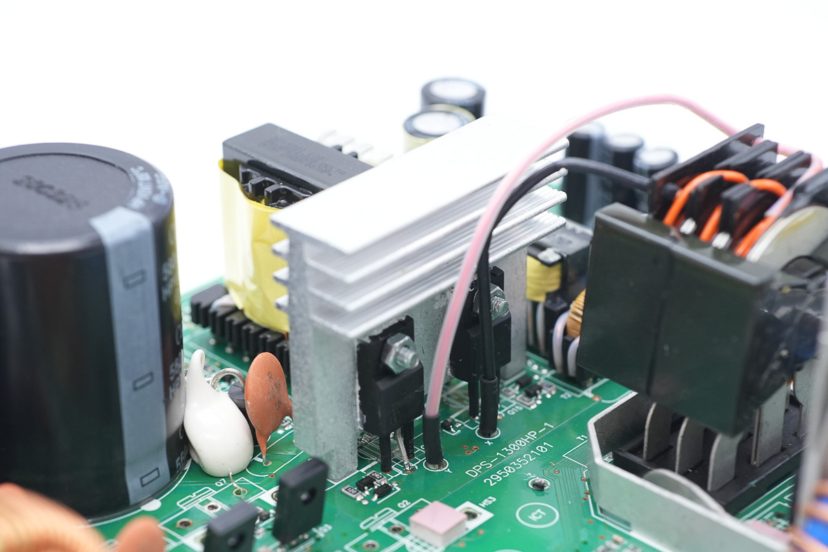
Two additional MOSFETs of the same model are fixed on the other side of the heat sink.
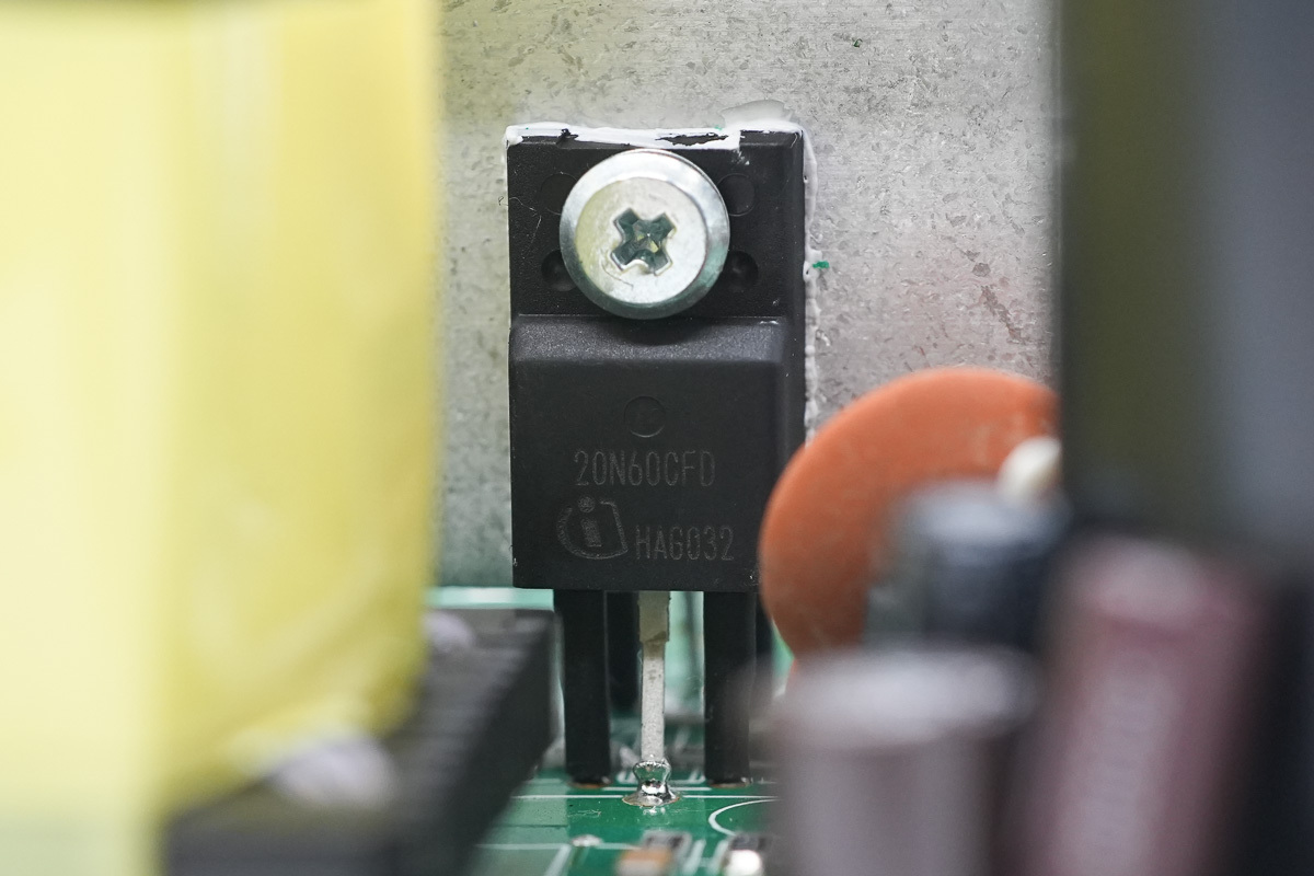
The phase-shifted full-bridge MOSFET is from Infineon, model SPA20N60CFD, NMOS, 600V and 220mΩ, adopting a TO-220FP package.
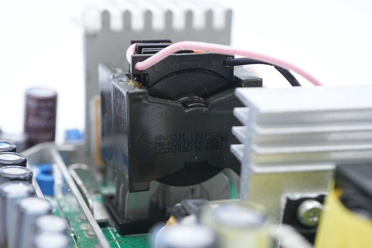
The primary winding of the transformer is wound with insulated wire, and the secondary winding is soldered using copper sheets.
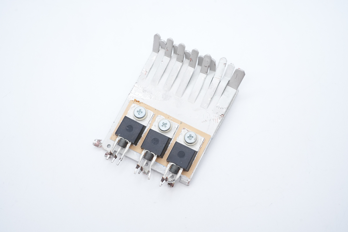
The synchronous rectifier MOSFETs are secured on a heat sink.
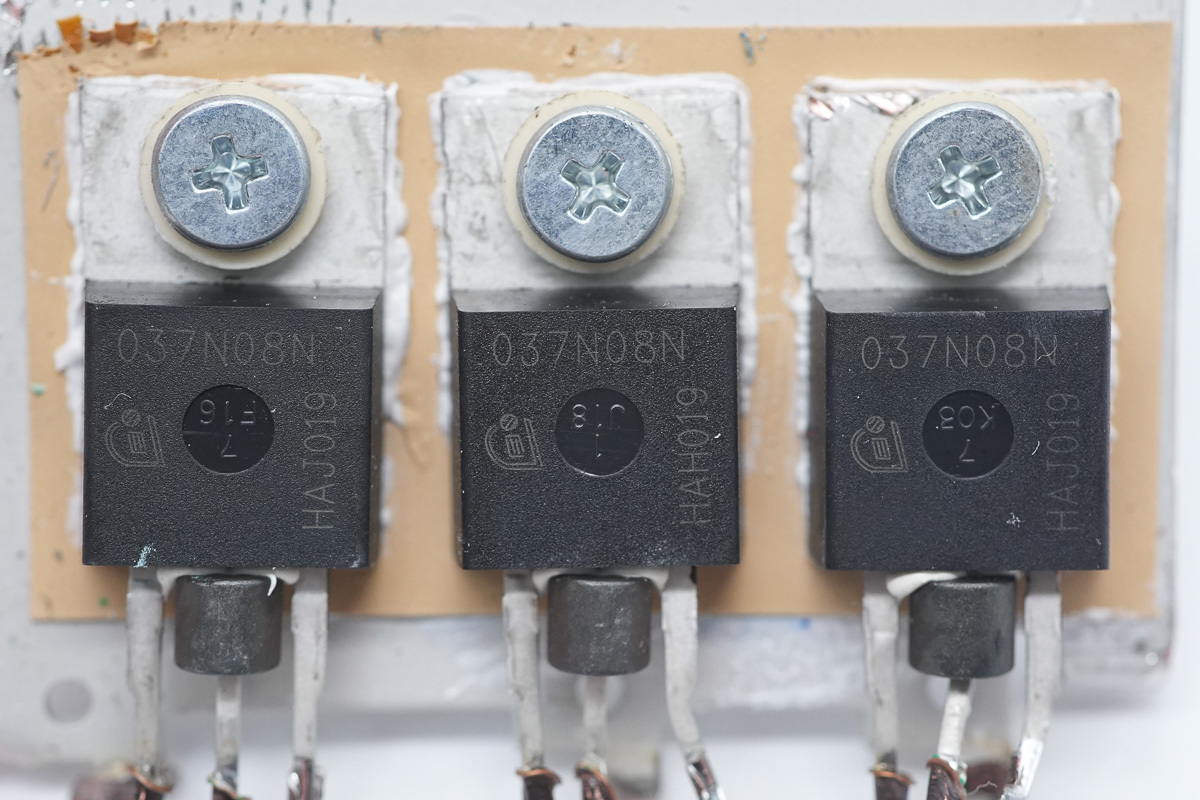
The synchronous rectifier MOSFETs are from Infineon, model IPP037N08N3 G, NMOS, 80V and 3.5mΩ, adopting a TO-220-3 package.
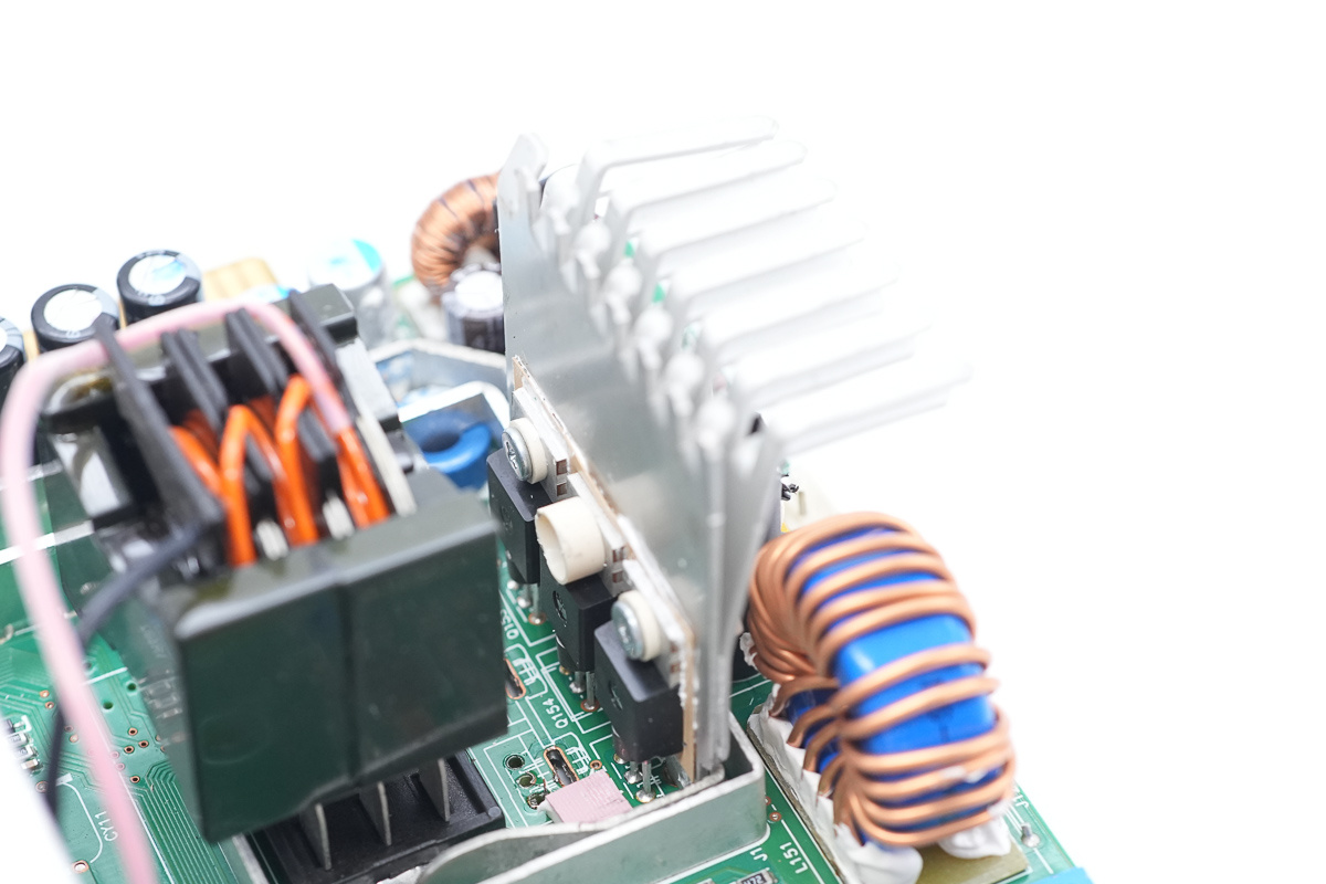
Three additional synchronous rectifier MOSFETs are fixed on another heat sink.
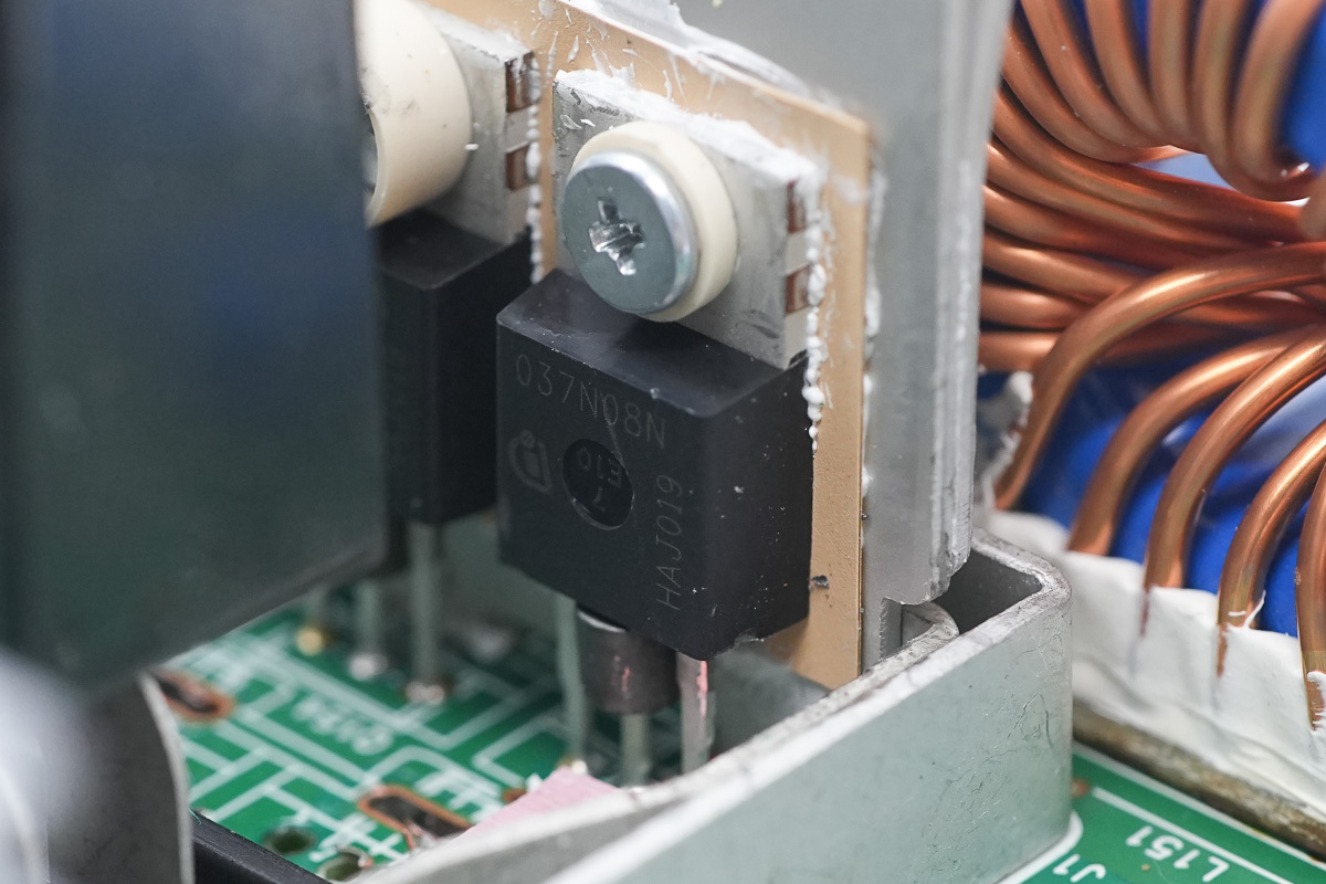
The synchronous rectifier MOSFETs are of the same model.
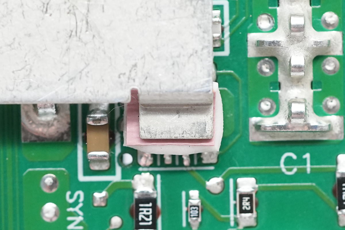
The driver is equipped with a thermal pad and dissipates heat through the connecting copper bar.
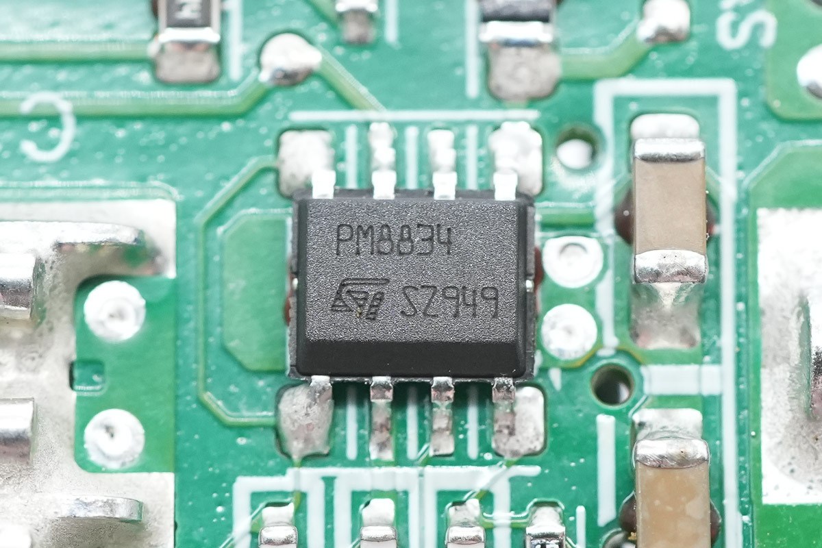
The driver is from ST, model PM8834, which is a dual low-side driver with 4A output current capability, adopting an SO-8 package.
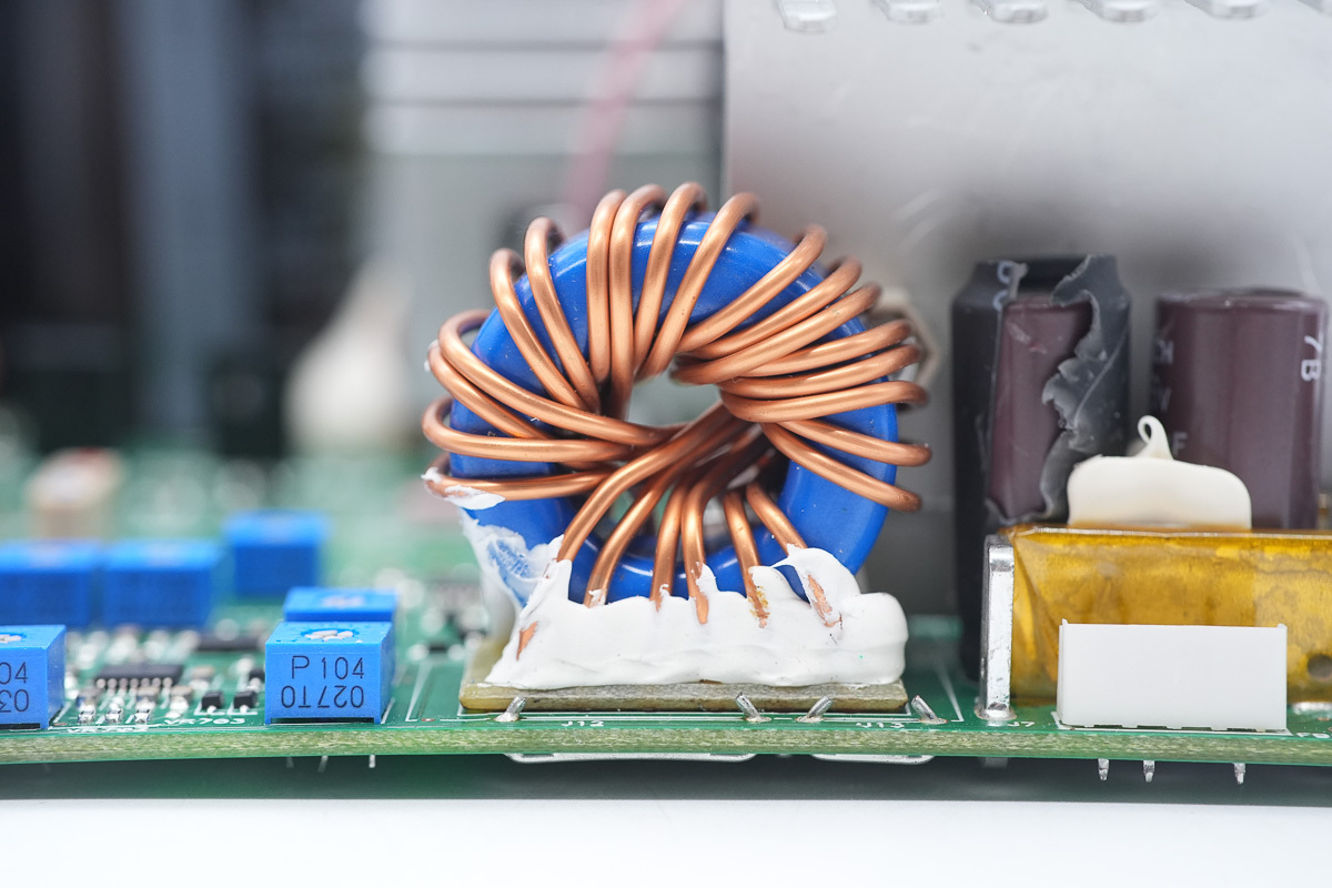
The output filtering choke, wound with parallel enameled wires and insulated with a Bakelite PCB at the bottom.
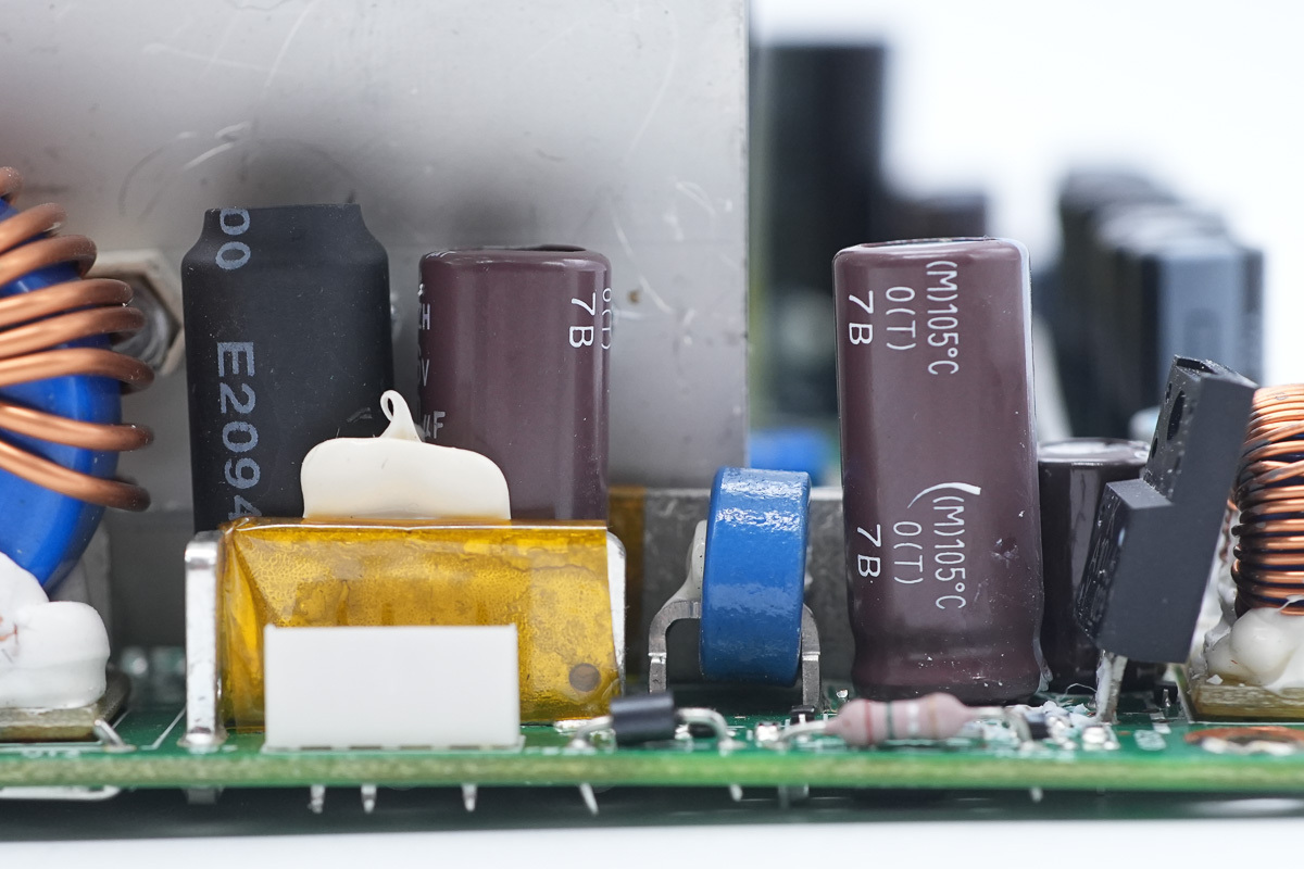
Three filtering caps are installed at the output end.
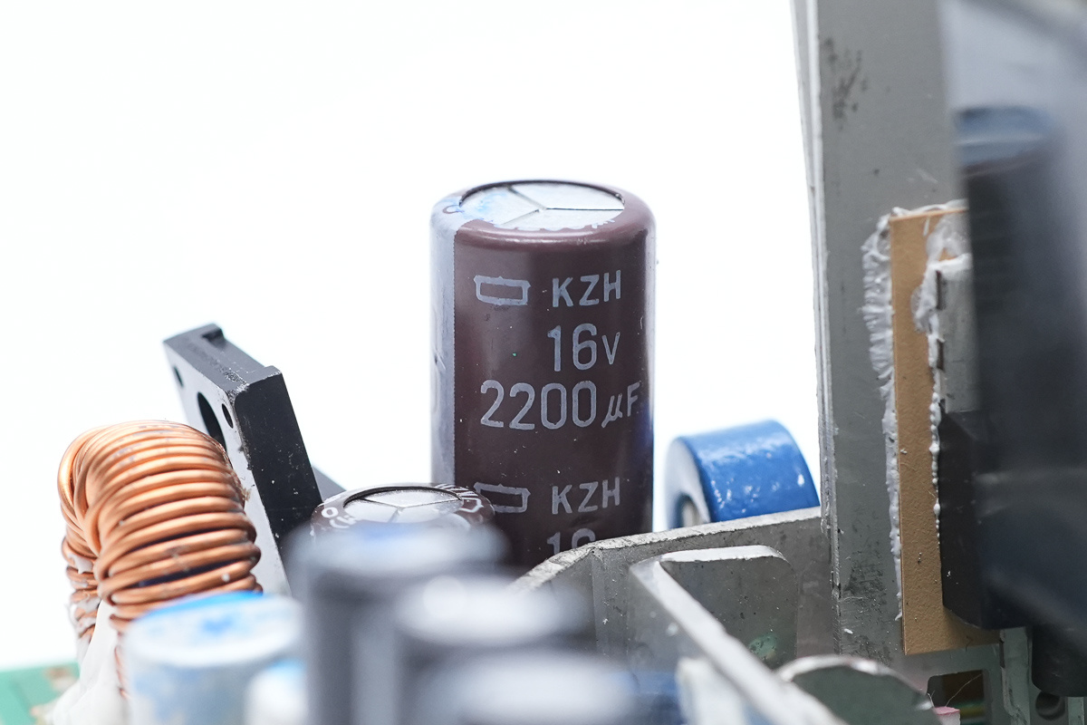
The filtering caps are from NCC, spec 16V 2200μF.
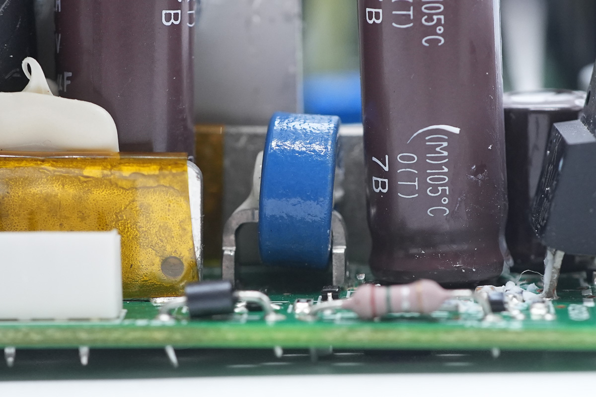
The output filtering choke.
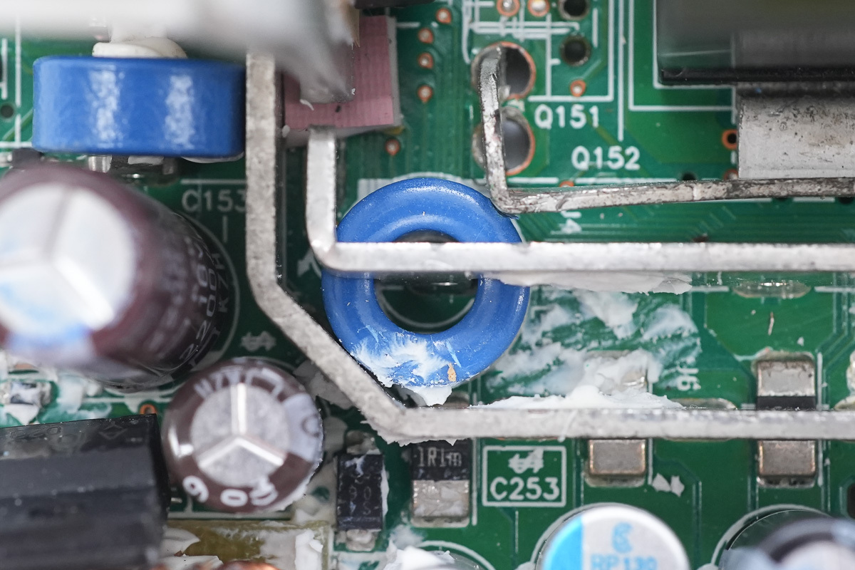
The copper bar is also equipped with a magnetic ring for filtering.
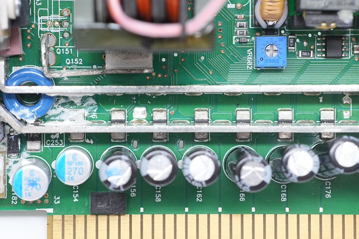
The output end is equipped with connecting copper bars, current sense resistors, and filtering caps.
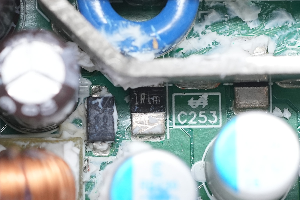
The current sense resistor, spec 1.1mΩ.
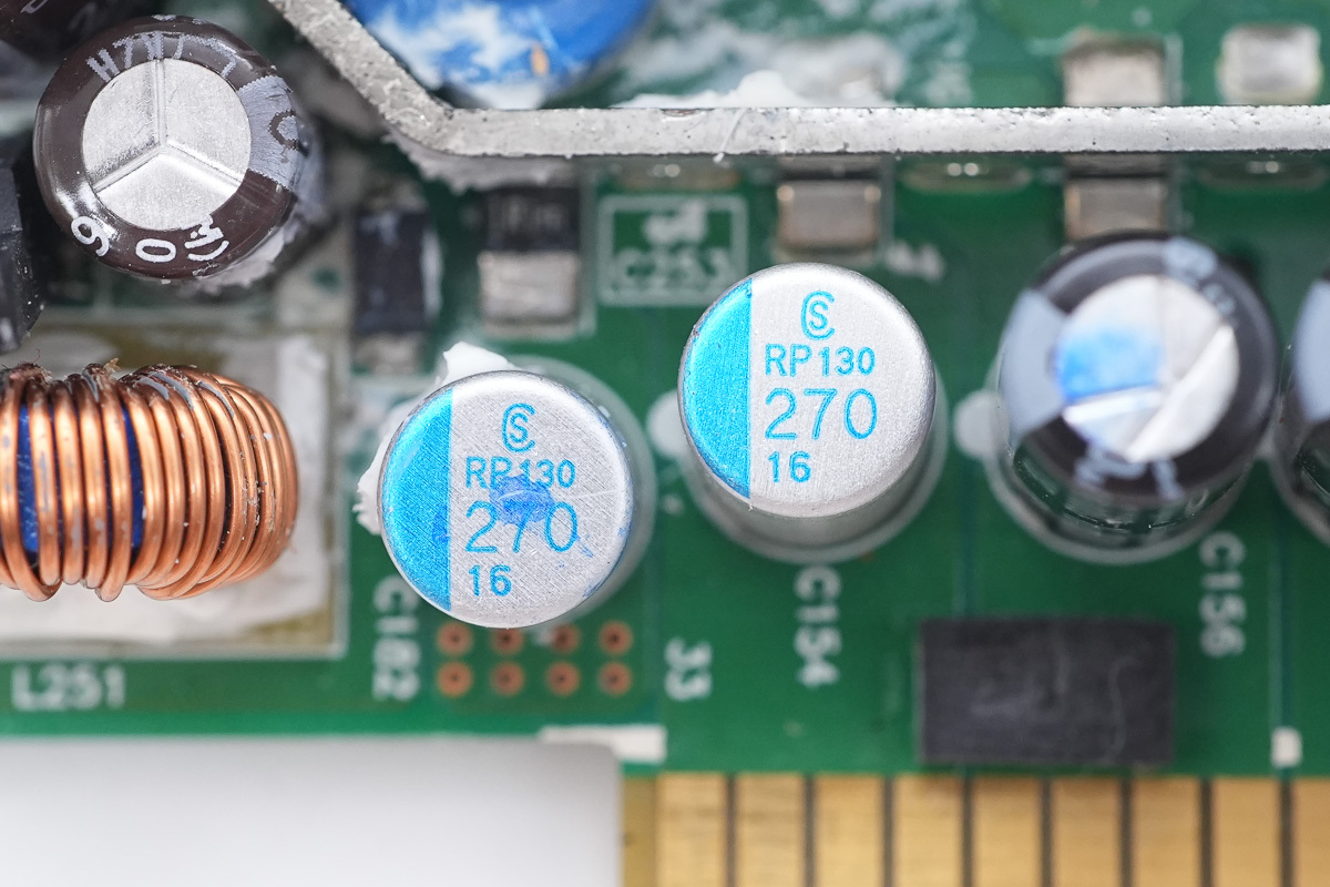
The filtering caps are from elite, spec 270μF 16V.
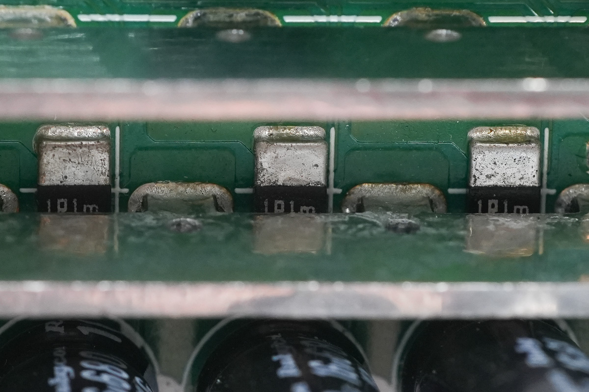
The current sense resistor, spec 1.1mΩ.
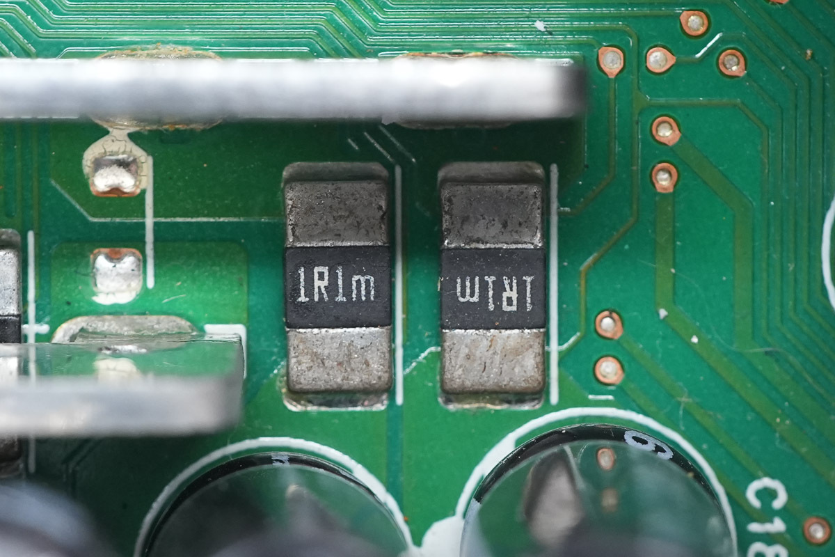
The current sense resistor, spec 1.1mΩ.
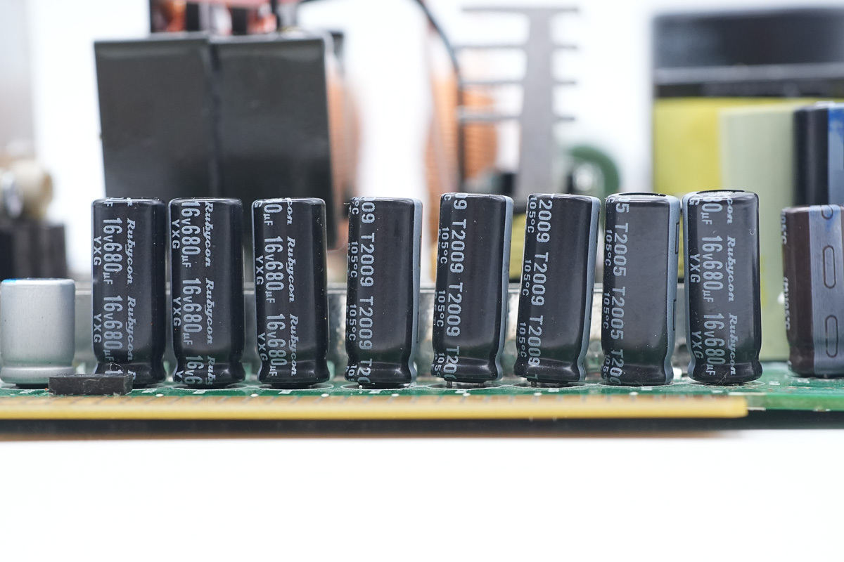
The filtering caps are from Rubycon, spec 16V 680μF.
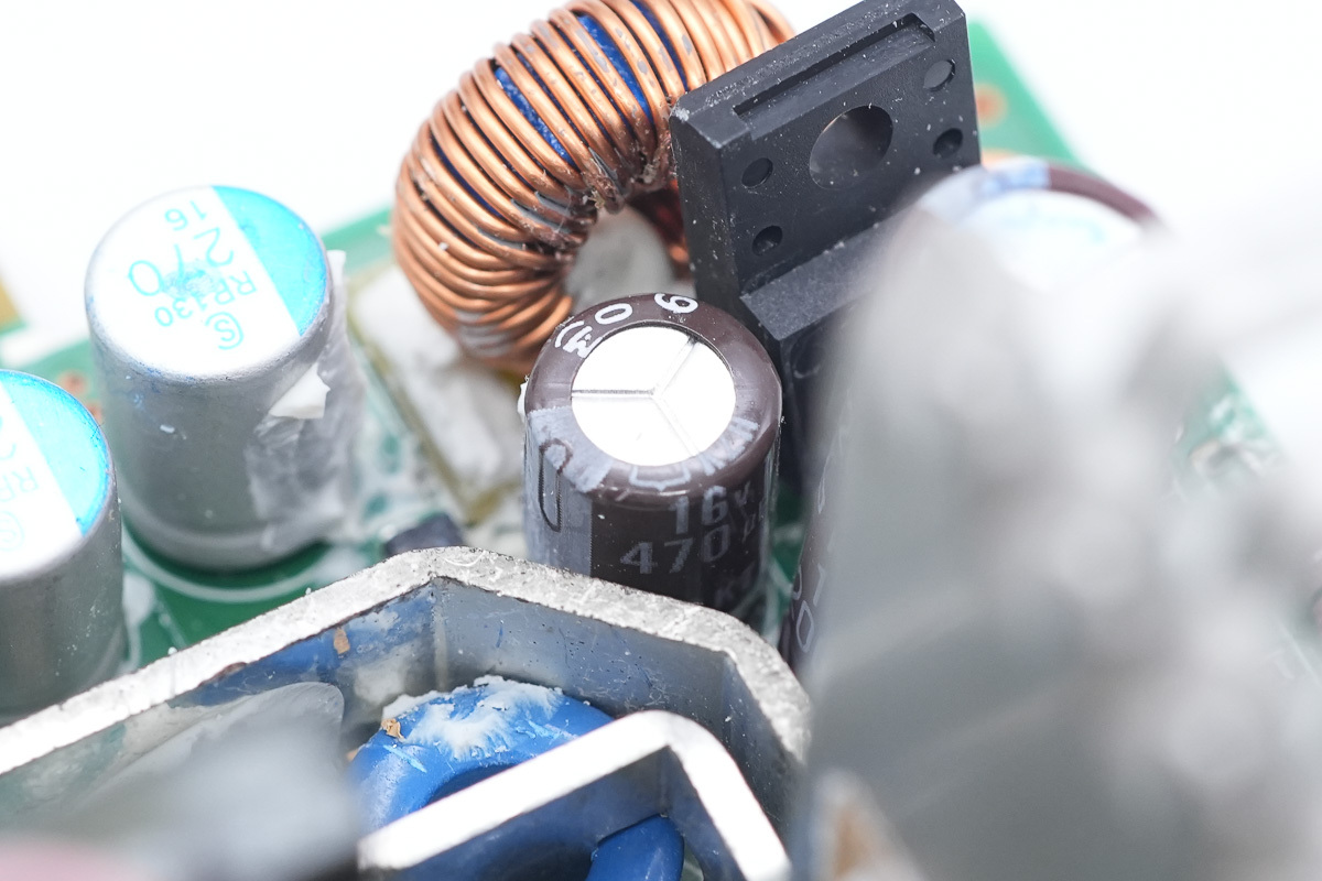
The filtering cap, spec 16V 470μF.
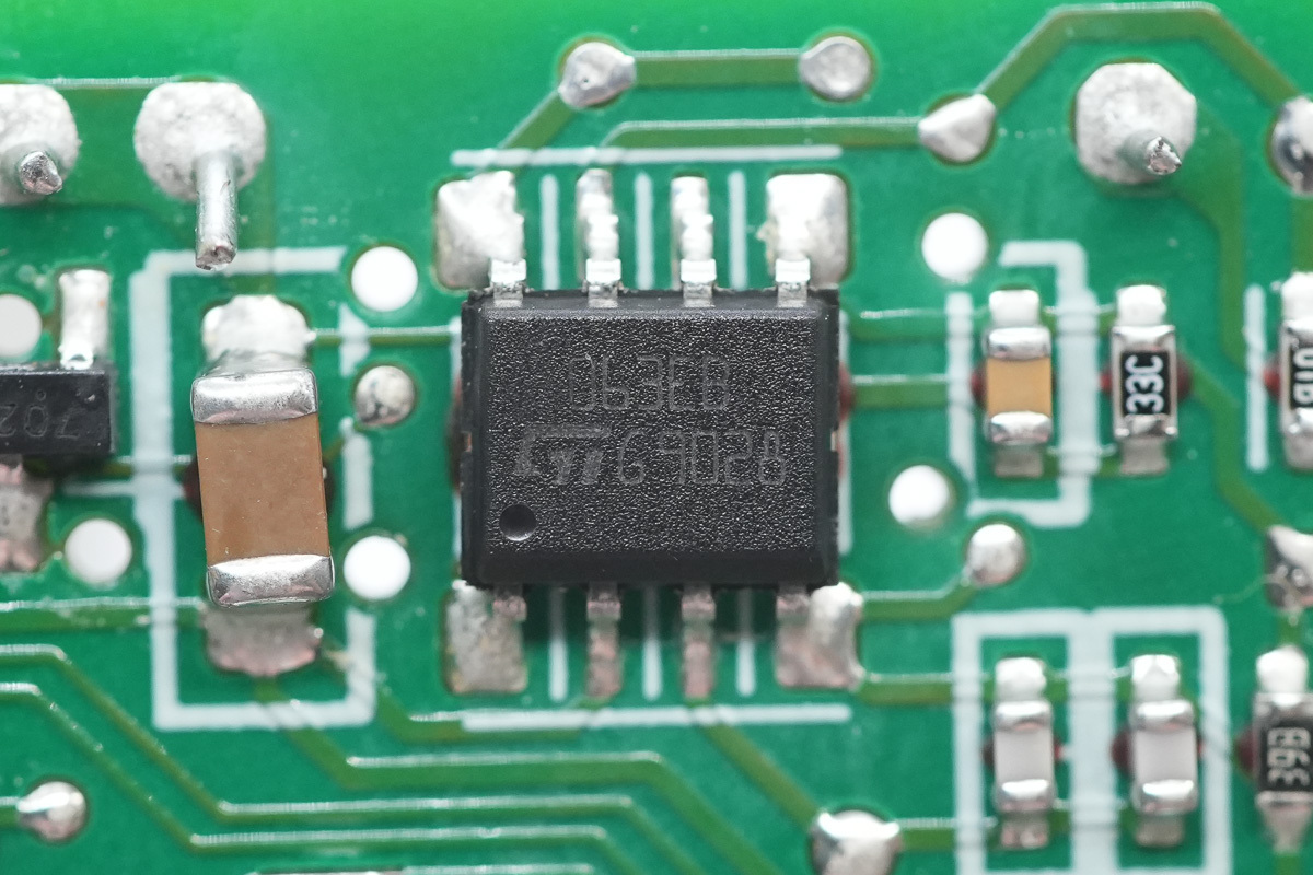
The power conversion chip is from ST, model MC34063EB, which integrates a switching MOSFET internally and supports step-up, step-down, and inverting applications, adopting an SO-8 package.
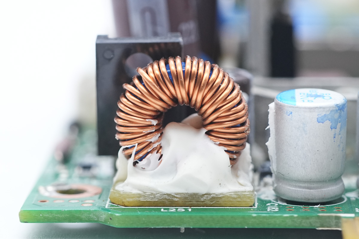
The choke is wound with enameled wire, with a Bakelite PCB at the bottom for insulation, and reinforced with potting compound.
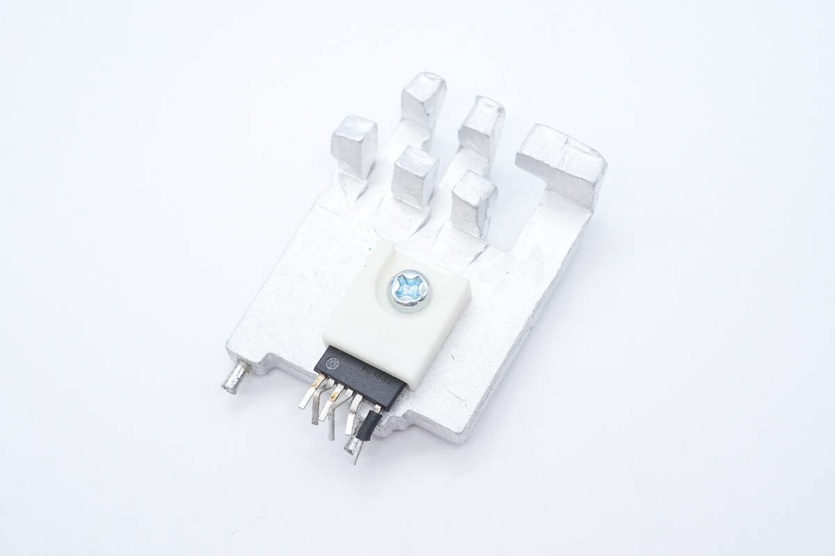
The standby power supply chip is equipped with a heat sink.
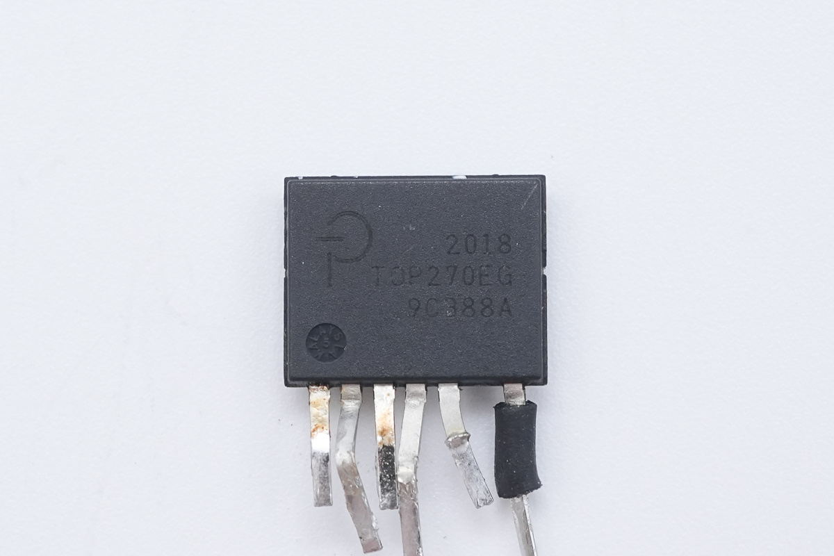
The standby power supply chip is from PI, model TOP270EG, belonging to the TOPSwitch-JX series, with an internally integrated 725V high-voltage switching MOSFET. Supporting up to 190W of output power when paired with a heat sink, it adopts an eSIP-7C package.
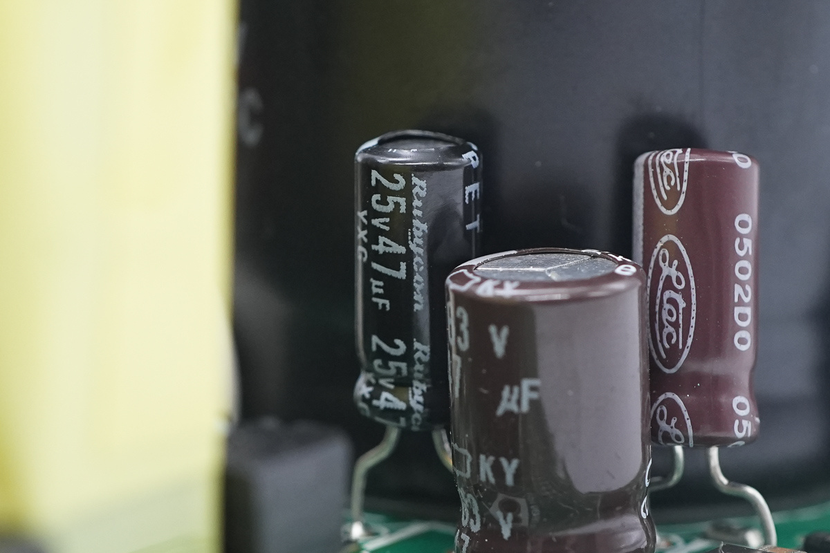
The filtering cap is from Rubycon, spec 25V 47μF.
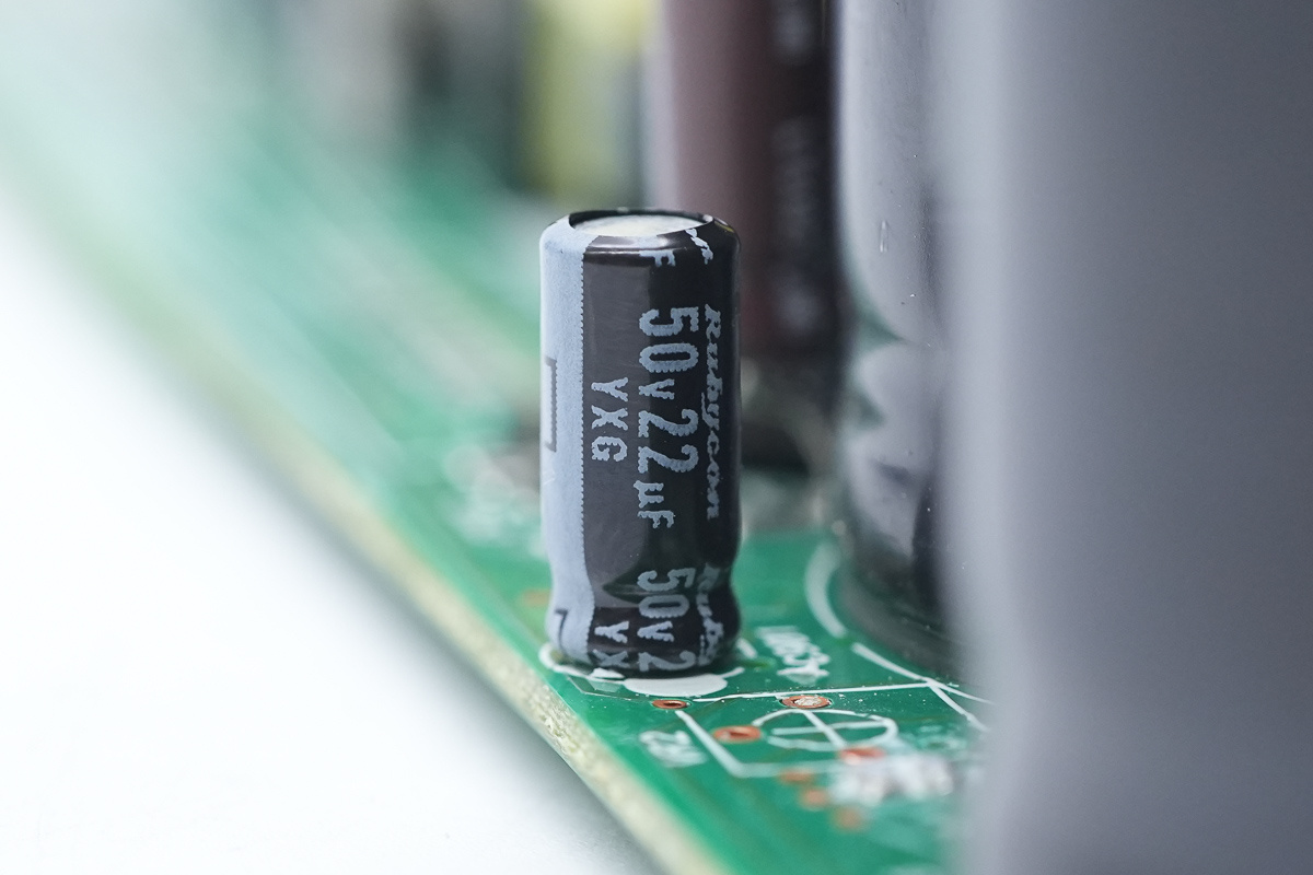
The filtering cap, spec 50V 22μF.
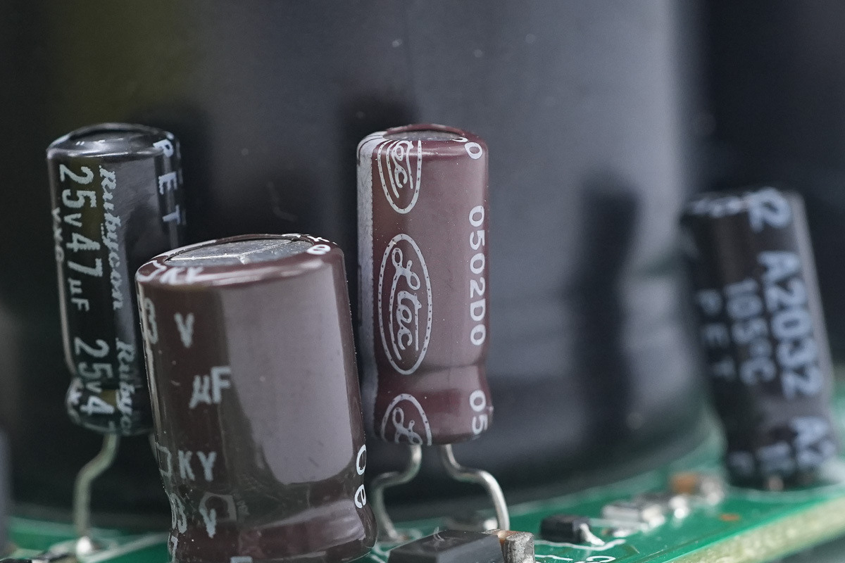
The filtering cap is from Ltec.
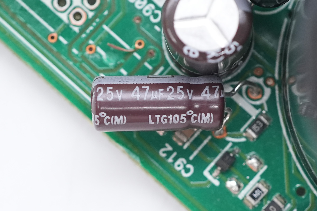
The spec is 47μF 25V.
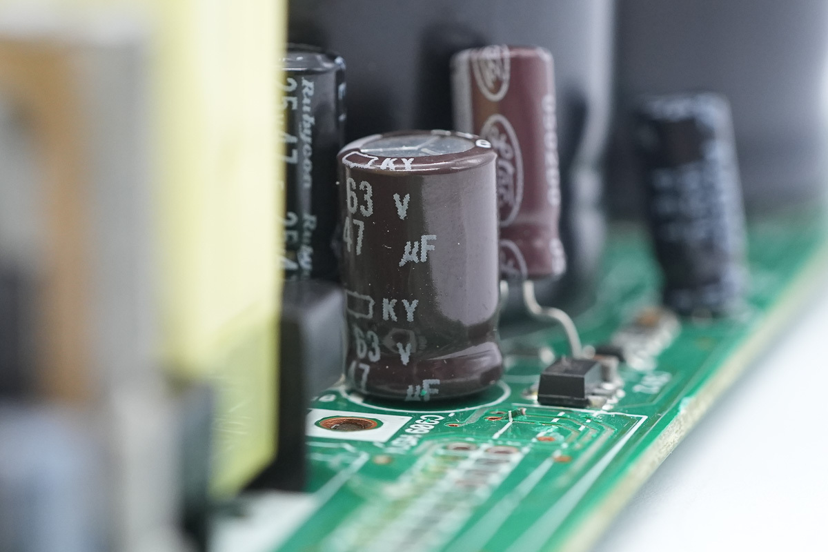
The filtering cap is from NCC, spec 63V 47μF.
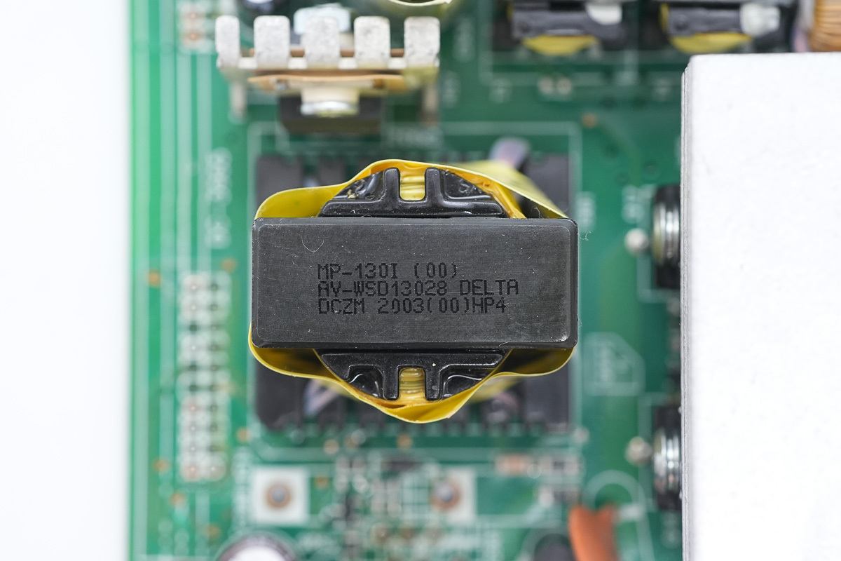
The transformer is wrapped with insulating tape.
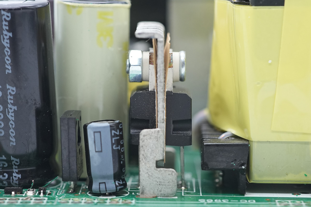
The rectifier MOSFET is equipped with a heat sink.
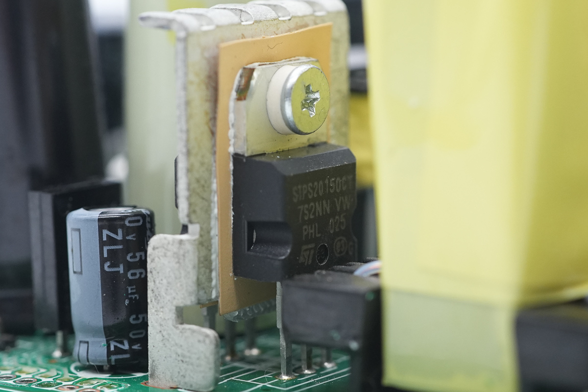
The rectifier MOSFET is from ST, model STPS20150CT, spec 150V 20A, adopting a TO-220AB package.
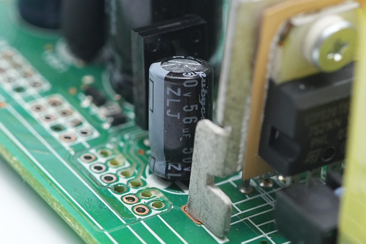
The filtering cap is from Rubycon, spec 50V 56μF.
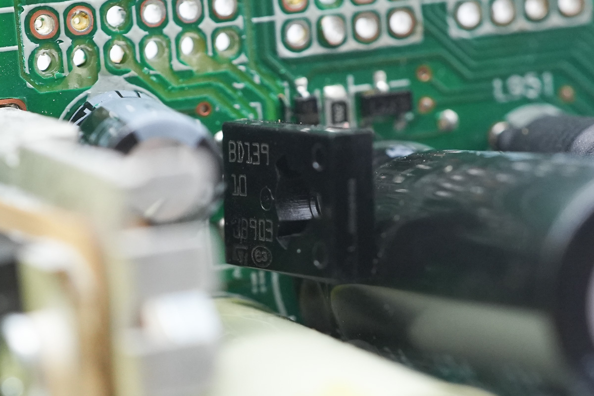
The transistor is from ST, model BD139-10, which is an NPN transistor rated at 80V 1.5A, adopting an SOT-32 package.
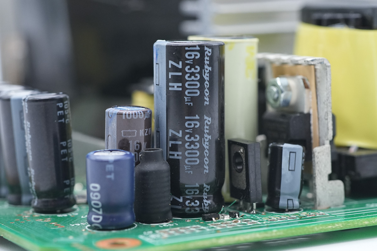
The filtering cap is from Rubycon, spec 16V 3300μF, and the other one is wrapped with insulating tape for insulation.
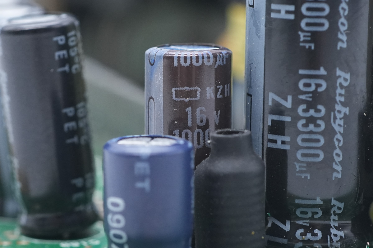
The filtering cap is from NCC, spec 16V 1000μF.
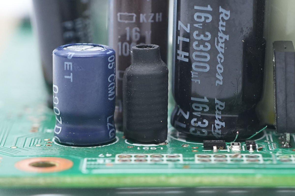
The filtering choke is covered with a heat-shrinkable tube for insulation.
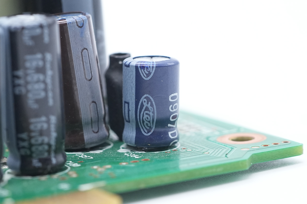
The filtering cap is from Ltec.
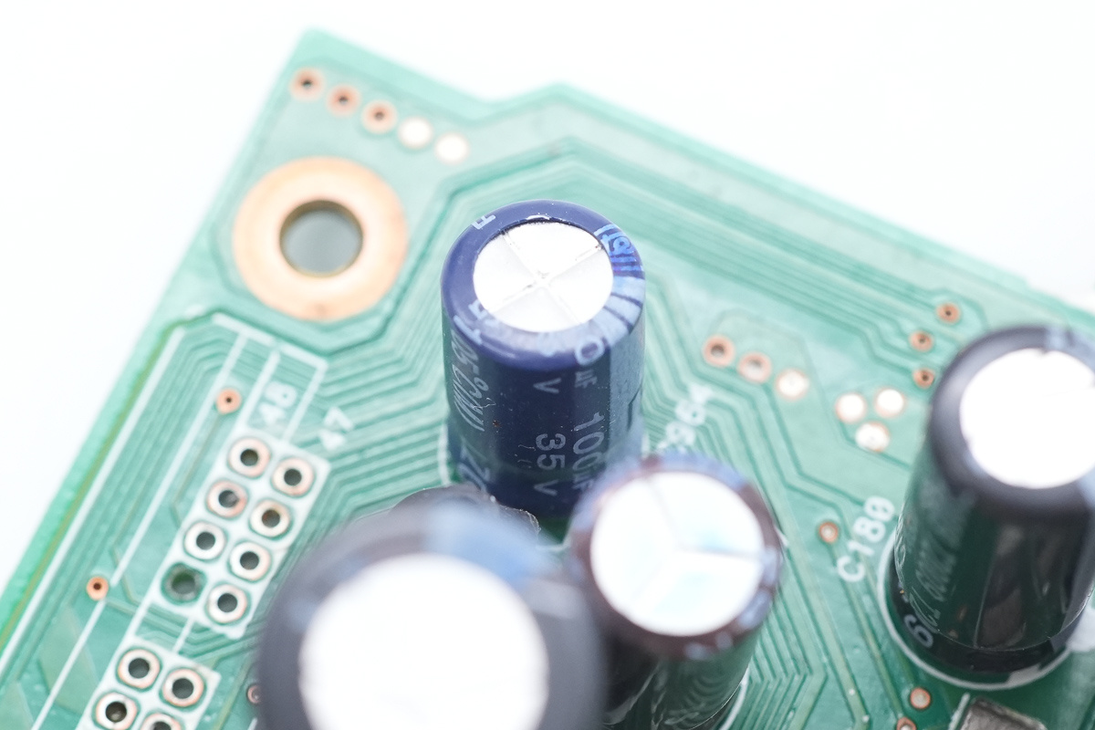
The spec is 100μF 35V.
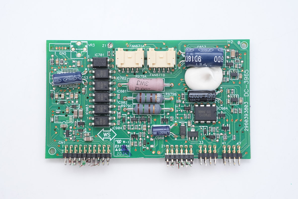
The inner side of the control PCB is equipped with an MCU, a management chip, and a voltage regulator chip.
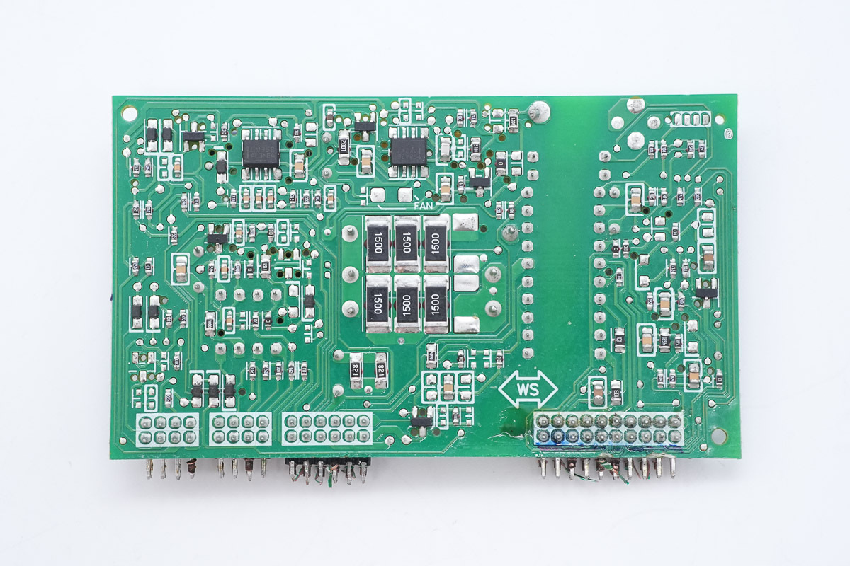
The outer side is equipped with an operational amplifier and a PWM chip.
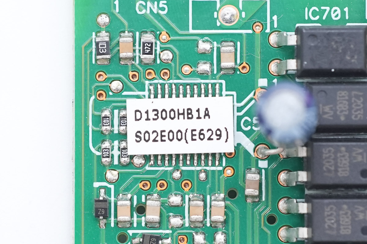
The MCU has a model sticker attached, marked D1300HB1A.
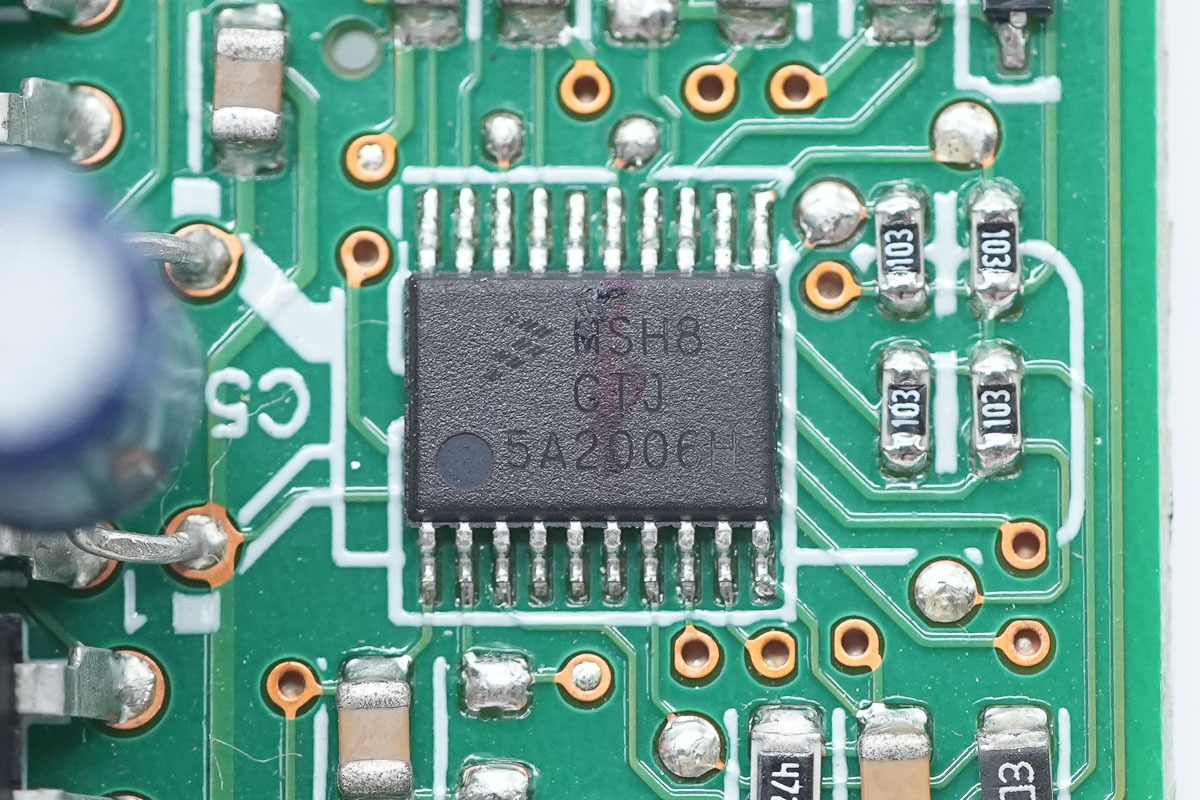
The MCU is from NXP, marked MSH8CTJ, model MC9S08SH8CTJ. It features a built-in 8-bit HCS08 MCU with 8KB of Flash and 512 bytes of RAM, an integrated 12-bit ADC, and adopts a 20-pin TSSOP package.
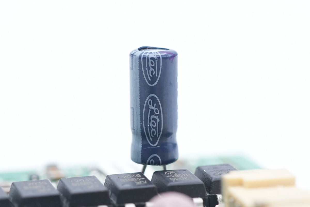
The filtering cap is from Ltec.
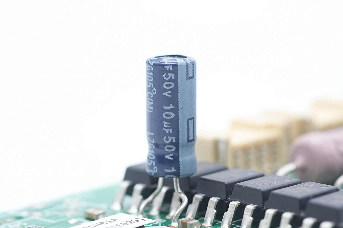
The spec is 100μF 50V.
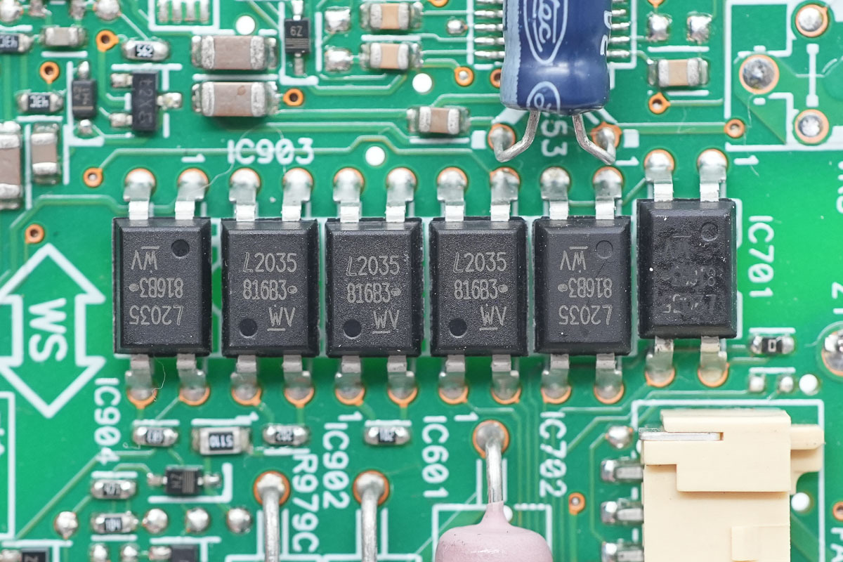
The optocoupler is from LITEON, model LTV-816-B, used for isolated communication.
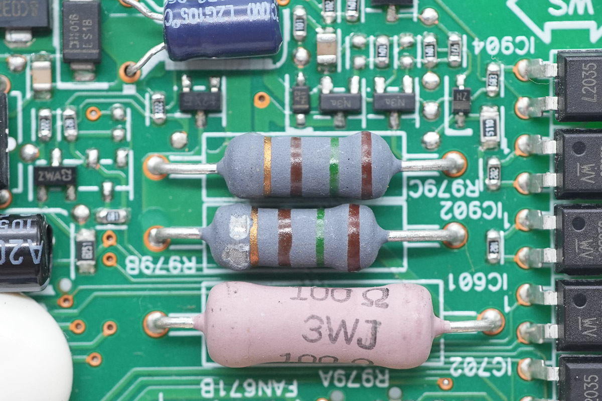
Two color-ring resistors.
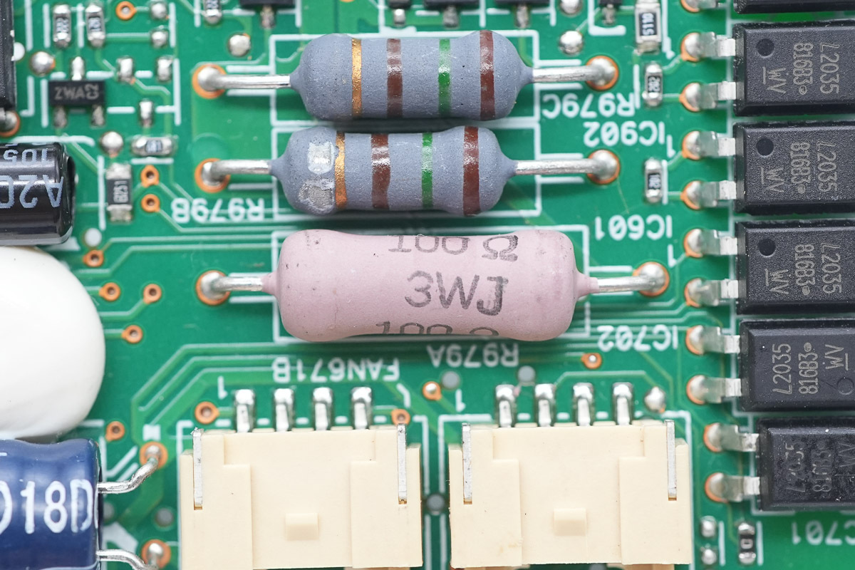
The resistor, spec 100Ω 3W.
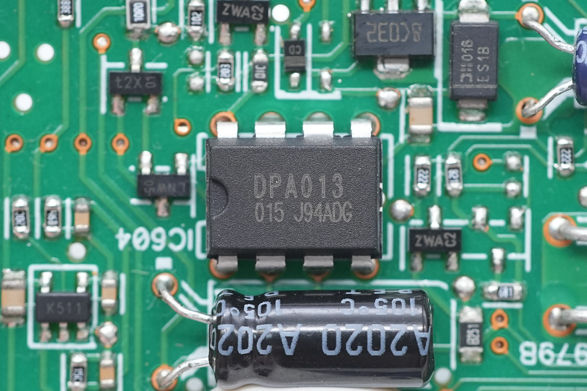
The management chip is from Delta, model DPA013, adopting a DIP-8 package.
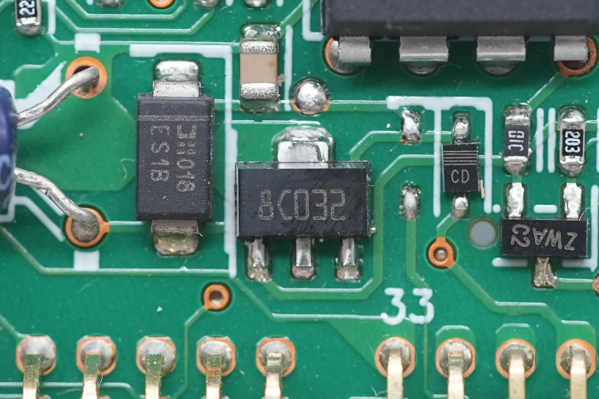
The voltage regulator chip is from ST, marked 8C, model L78L05A, supporting a 30V input voltage, a 5V output voltage, and a 100mA output current, adopting an SOT-89 package.
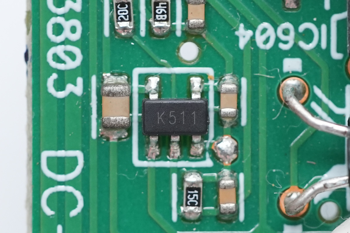
The voltage comparator is from ST, marked K511, model TS391ILT, which is a low-power single voltage comparator adopting an SOT-23-5 package.
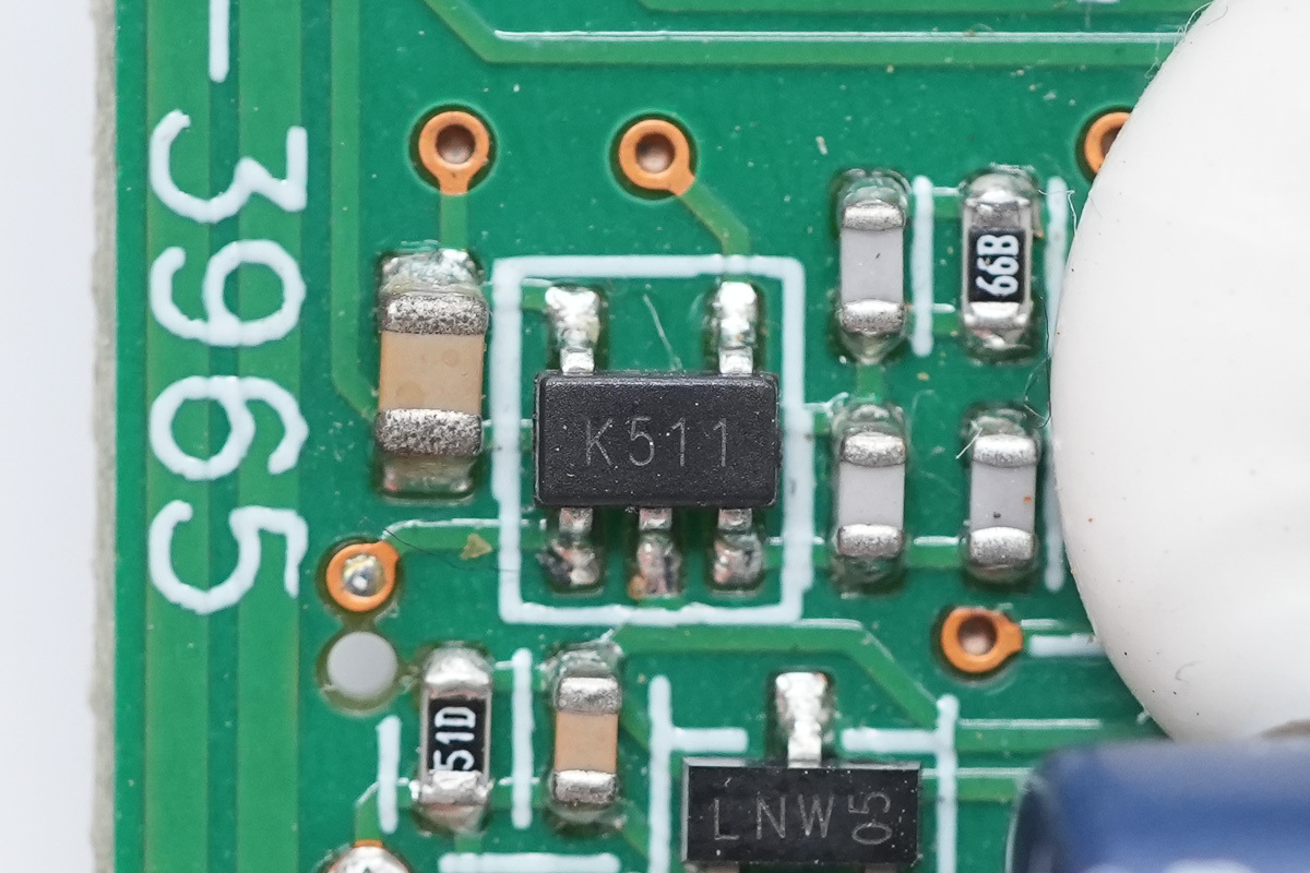
The other one shares the same model.

The 150Ω SMD resistors.
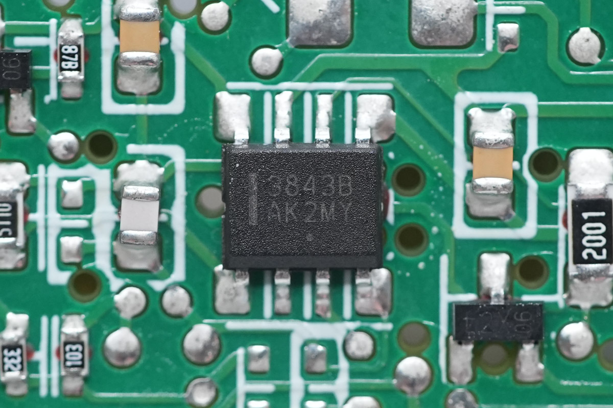
The PWM chip is from onsemi, model UC3843B, which is a high-performance fixed-frequency current-mode controller adopting an SOIC-8 package.
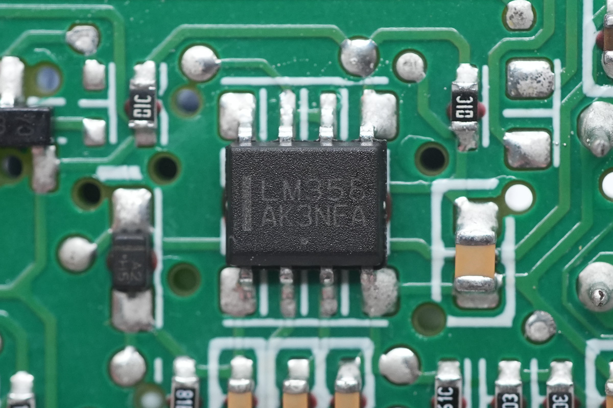
The operational amplifier uses the ST LM358.
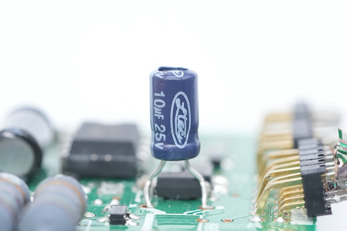
The filtering cap, spec 10μF 25V.
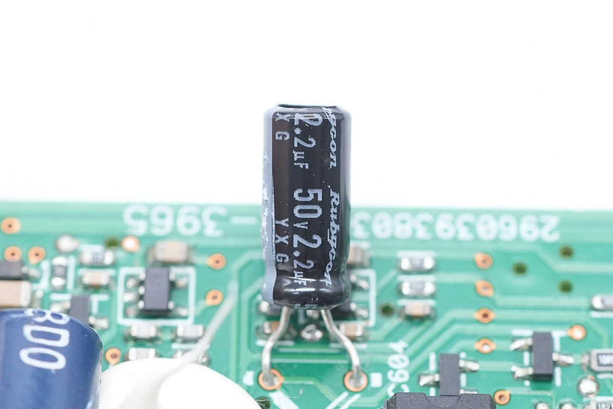
The filtering cap, spec 50V2.2μF.
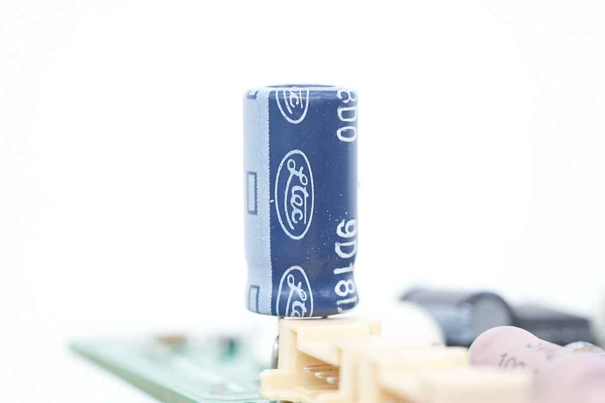
The filtering cap is from Ltec.
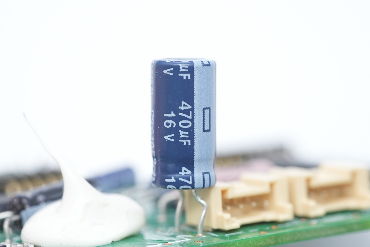
The spec is 470μF 16V.
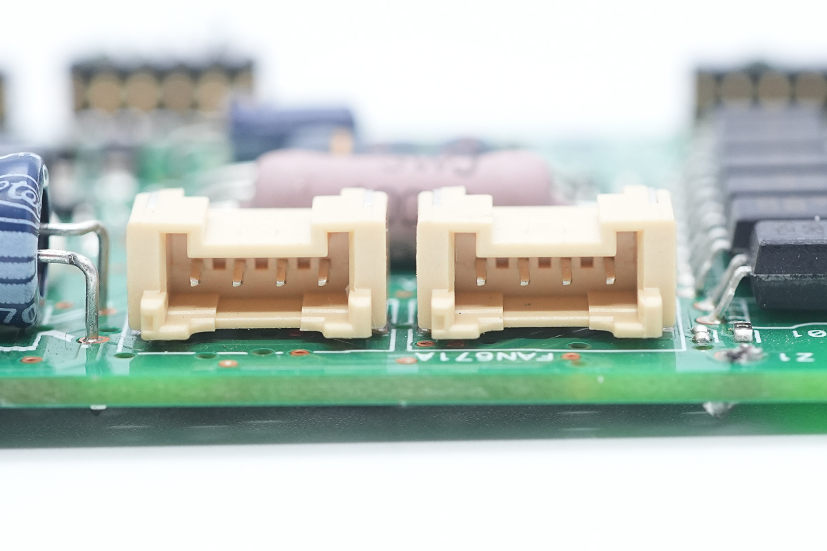
The connector socket for the cooling fan.
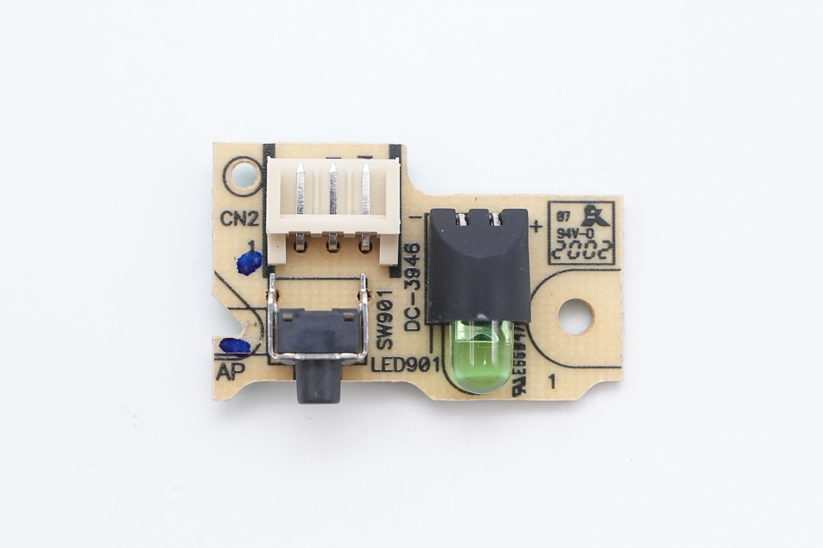
There is an LED indicator and a button PCB.
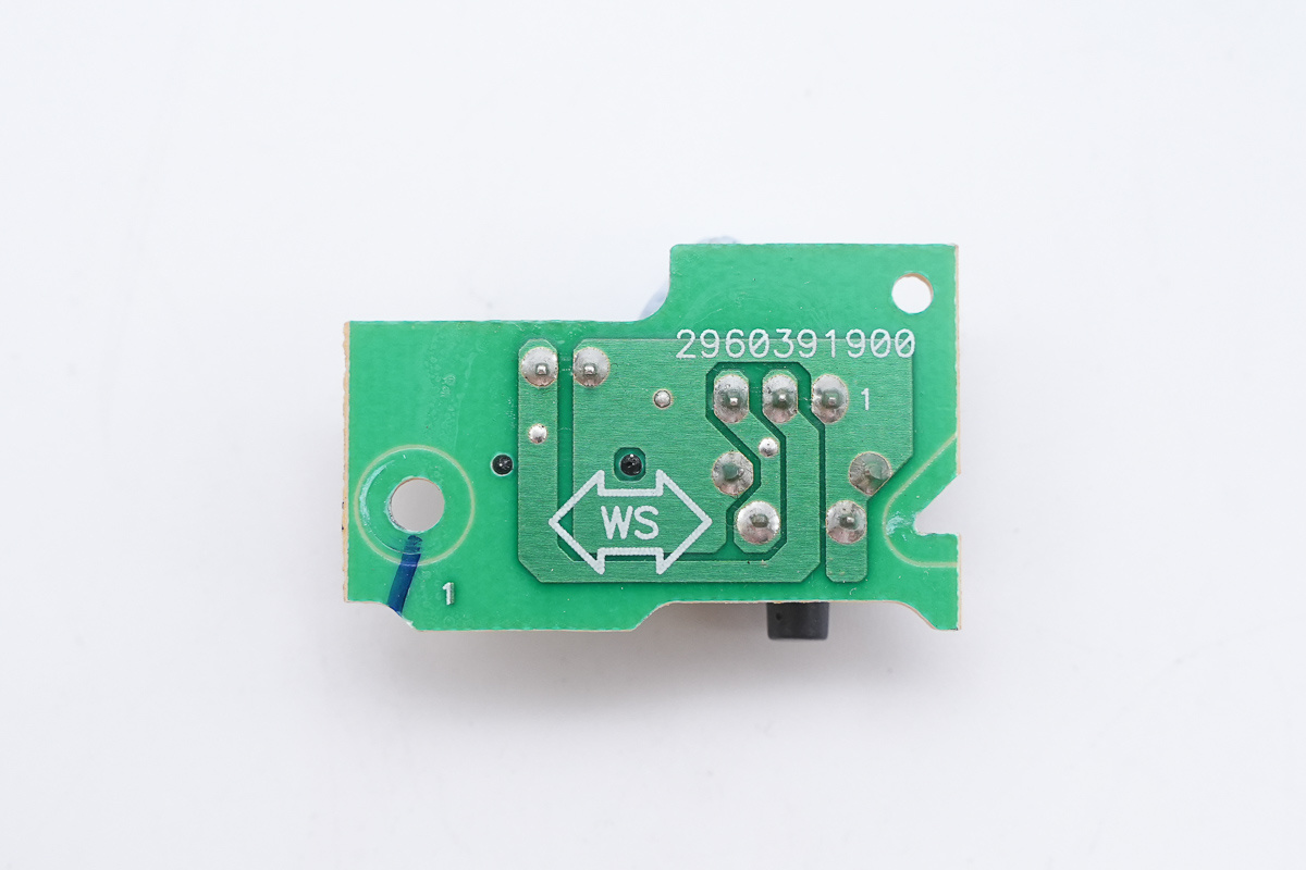
The back of the PCB features connection traces.
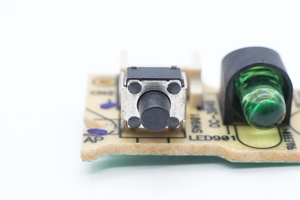
The test button.
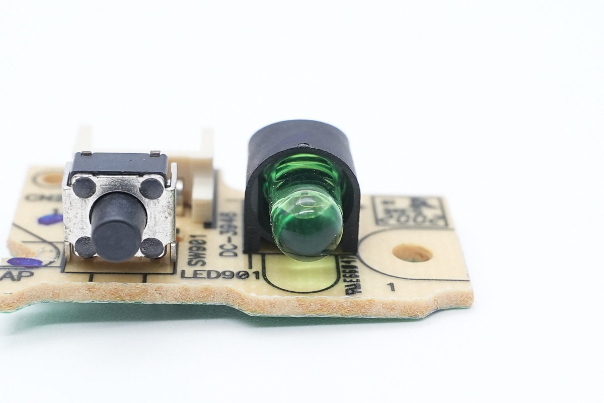
The green LED indicator.
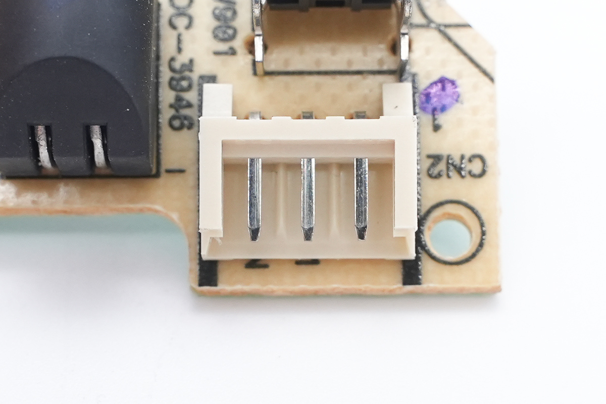
The connection socket.
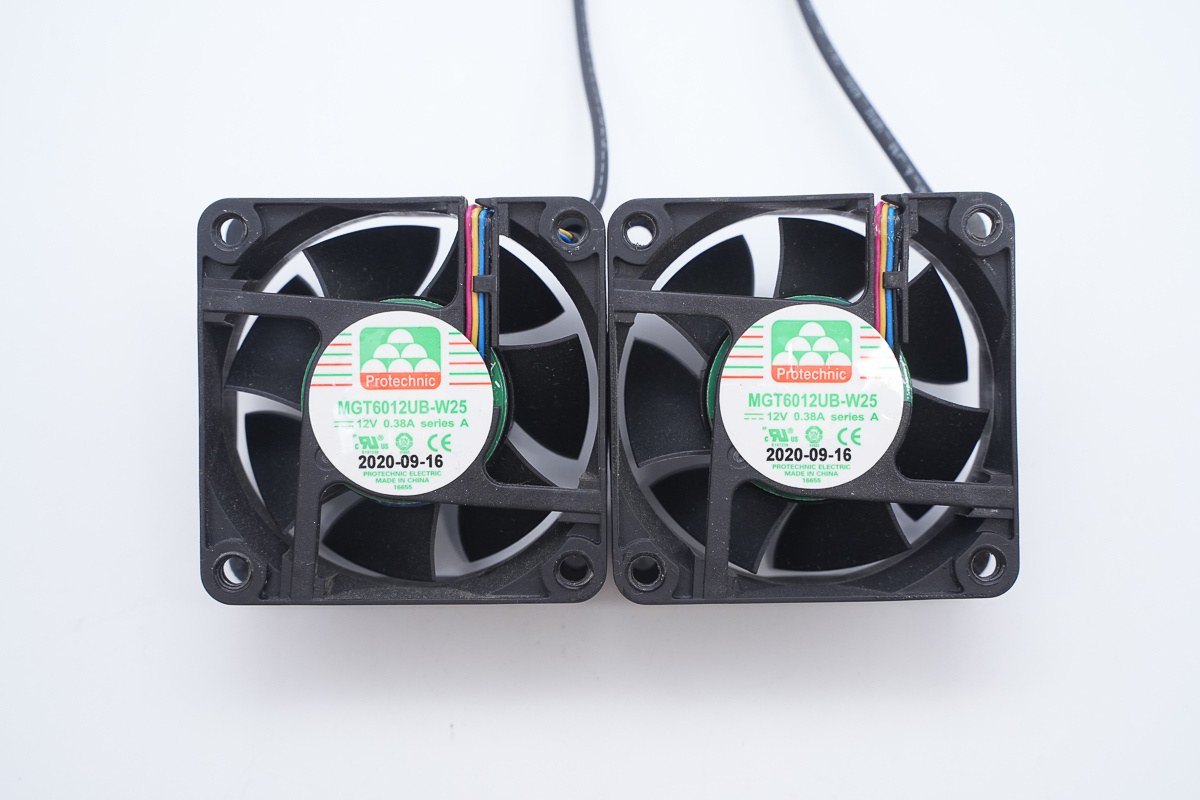
The power supply has two built-in cooling fans.
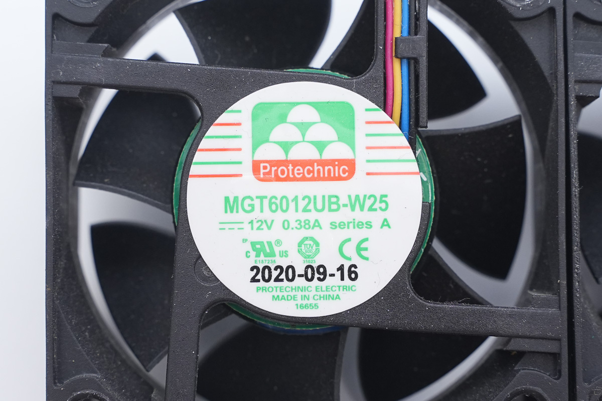
The cooling fan is from Protechnic, model MGT6012UB-W25, spec 12V 0.38A, made in China.

Well, those are all components of the DELL 1300W SiC Workstation Power Supply.
Summary of ChargerLAB
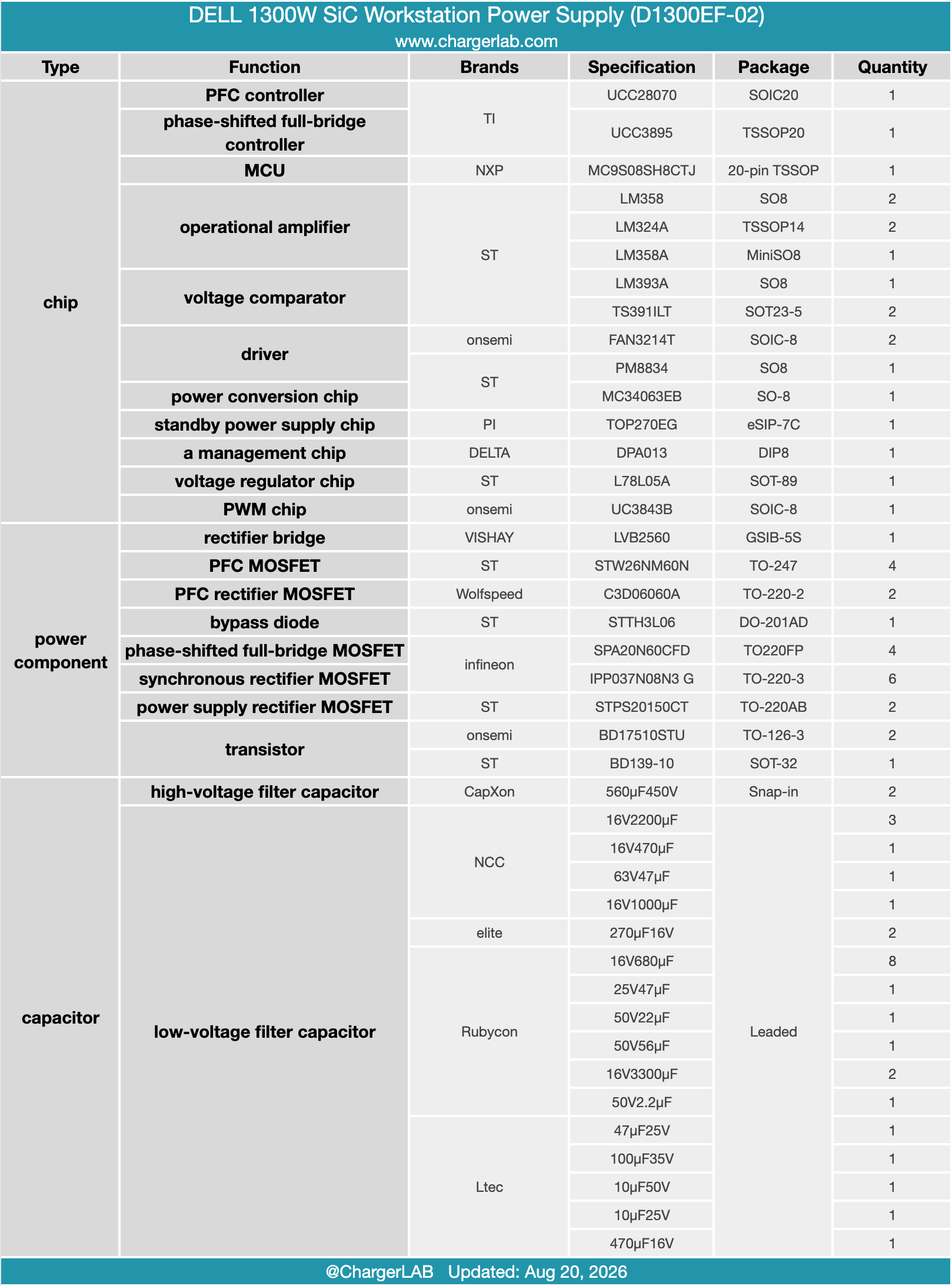
DELL 1300W Workstation Power Supply (Model: D1300EF-02) featuring 100-240V universal AC input, a 12V main DC output partitioned across 10 independent channels (up to 216W per channel), and a 12V/6A standby rail. Cooling is provided by an internal fan pulling air from the rear exhaust vent toward the input side.
Teardown analysis reveals an advanced topology consisting of Interleaved PFC, a PSFB converter, and SR. It relies on a TI UCC28070 PFC controller combined with a UCC3895 PSFB controller. The active PFC stage utilizes ST STW26NM60N MOSFETs paired with Wolfspeed C3D06060A SiC Schottky diodes.
Primary-side full-bridge switching relies on Infineon SPA20N60CFD MOSFETs driven through isolation transformers. Secondary synchronous rectification uses Infineon IPP037N08N3 G MOSFETs, while standby regulation is managed by a PI TOP270EG IC. OCP across all individual outputs is implemented using dedicated sense resistors and operational amplifiers for precise current monitoring.