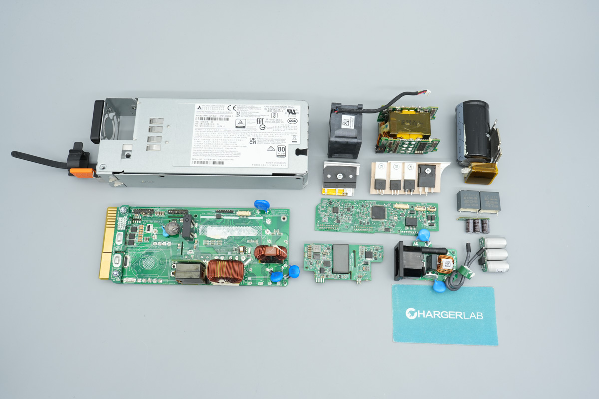

Introduction
In this teardown, we look at the GreatWall GW-CDMDSP1200C SiC server power supply. It supports a 100-240V AC input and a 240V HVDC input, delivering a 12V main output at 100A and a 5V standby output at 6A, totaling a rated power output of 1200W.
The AC input side is equipped with ventilation slots, a power receptacle, and LED indicators, whereas the output end features a gold-finger connector for hot-swap capability. Boasting Platinum-grade efficiency, the unit utilizes a PFC + half-bridge LLC + synchronous rectification architecture with PMBus communication support. Let's dive into the teardown by ChargerLAB to explore the internal layout and component selection.
Product Appearance
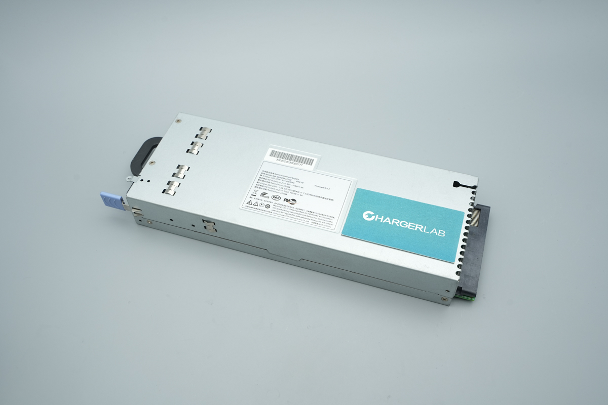
The GreatWall power supply adopts a galvanized steel sheet chassis, with a label affixed to the front.
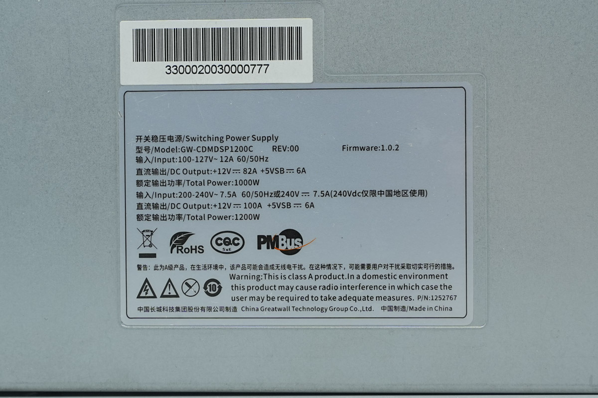
The power supply info label:
Model: GW-CDMDSP1200C
Input: 100-127V ~ 12A 60/50Hz
Output: +12V ⎓ 82A, +5VSB ⎓ 6A
Rated Output Power: 1000W
Input: 200-240V ~ 7.5A 60/50Hz or 240V ⎓ 7.5A (240Vdc restricted to China)
Output: +12V ⎓ 100A, +5VSB ⎓ 6A
Rated Output Power: 1200W
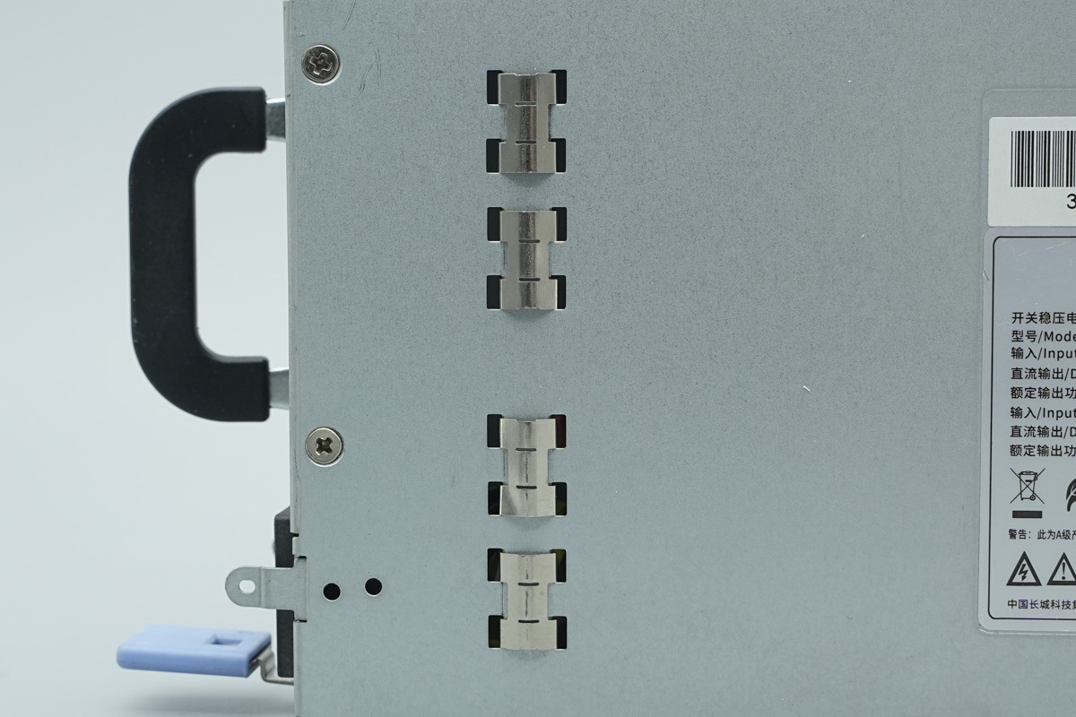
Grounding spring contacts are provided on the front of the chassis.
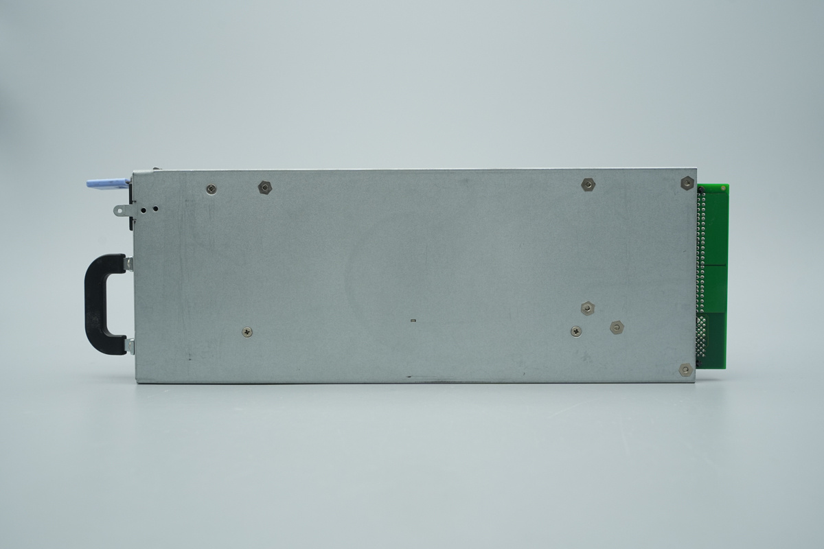
Fixing screws are provided on the back.
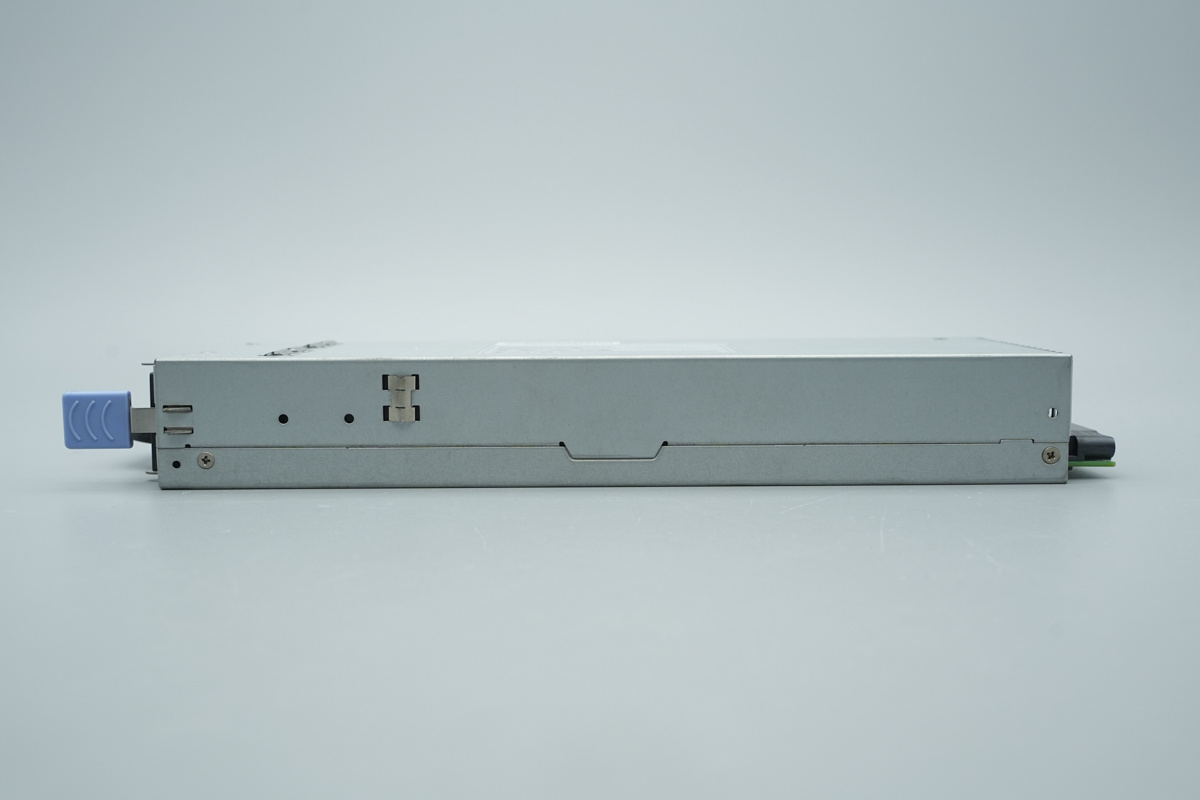
Locking buckles and grounding spring contacts are located on the side of the chassis.
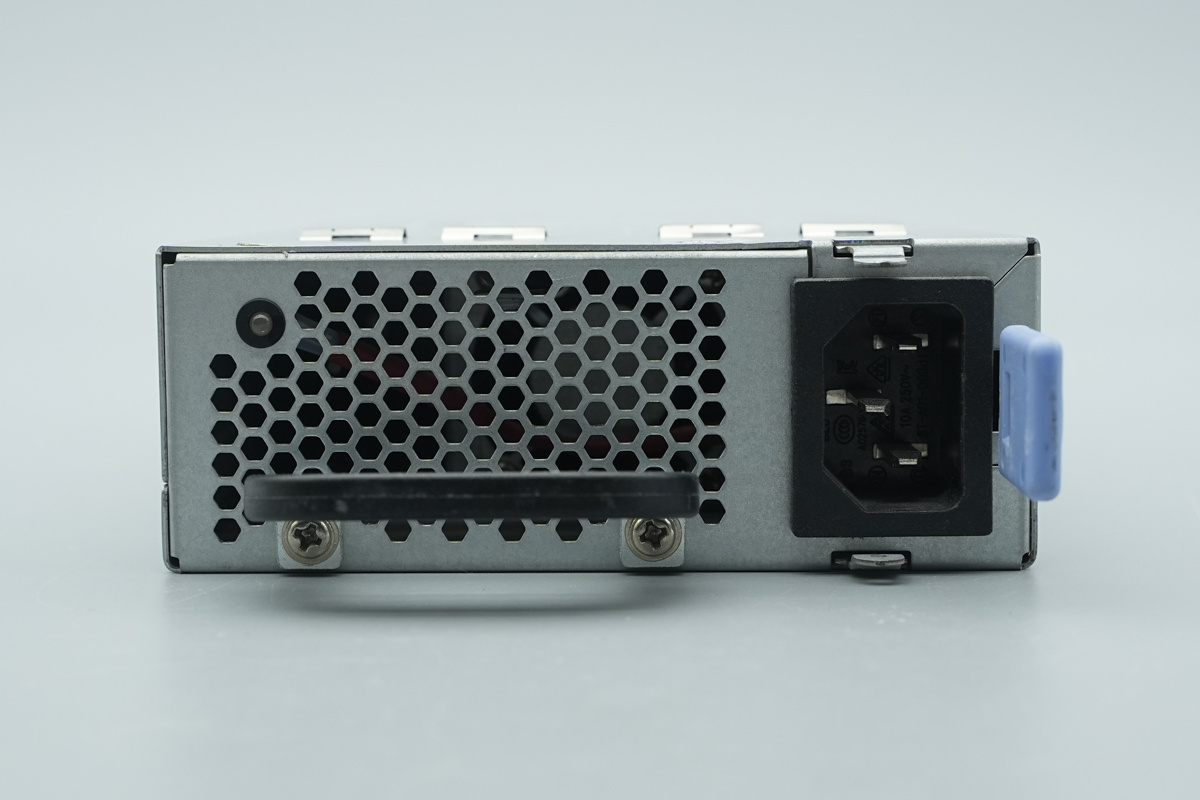
The input end is equipped with a handle, an LED indicator, cooling ventilation holes, an IEC power socket, and a latch release handle.
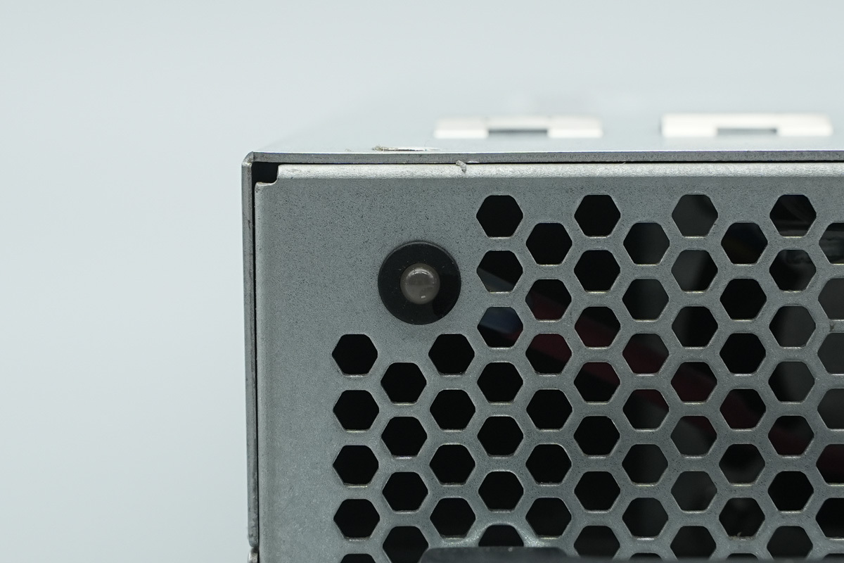
There is the LED indicator.
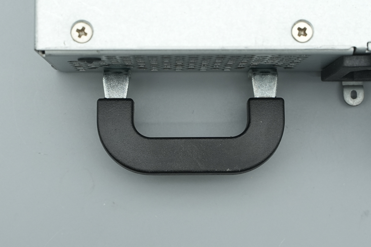
The handle is secured with screws.
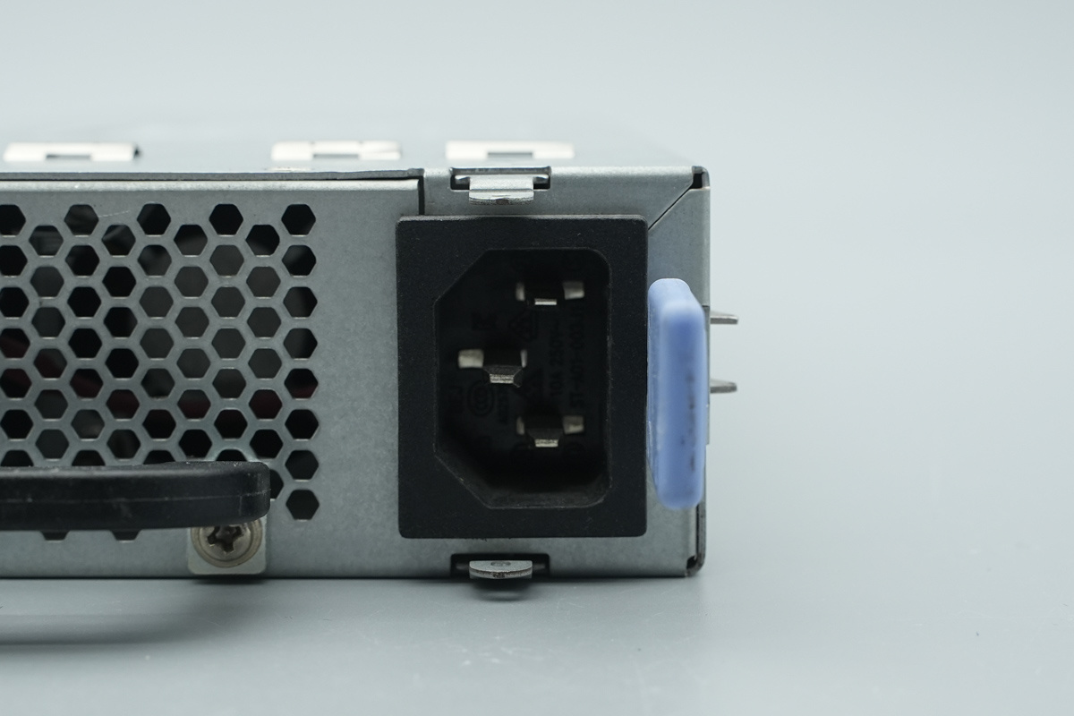
The IEC power input socket.
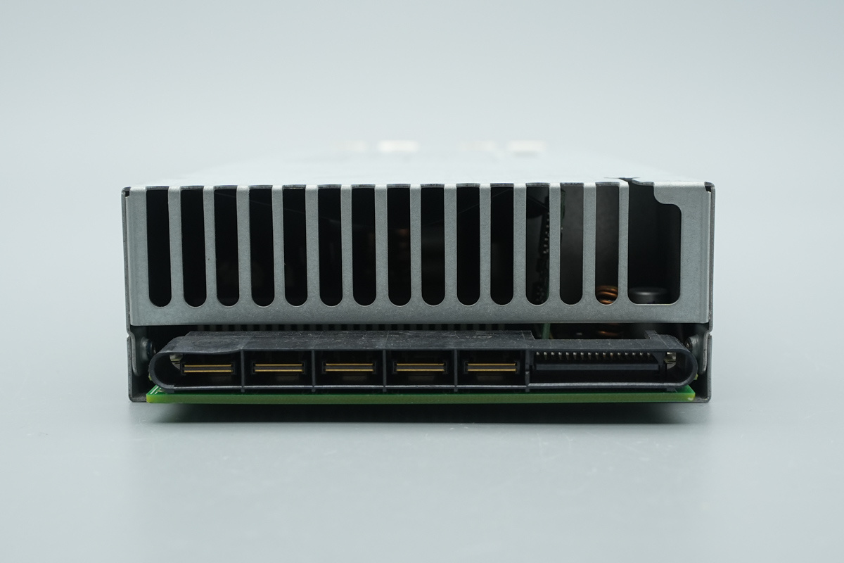
The output end features a cooling grille and a connector.
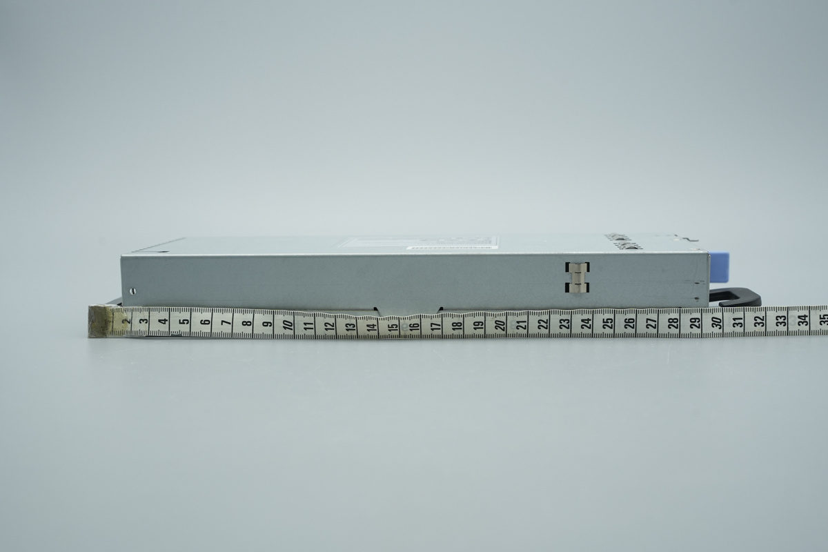
The length of the power supply is about 293mm (11.535 inches).
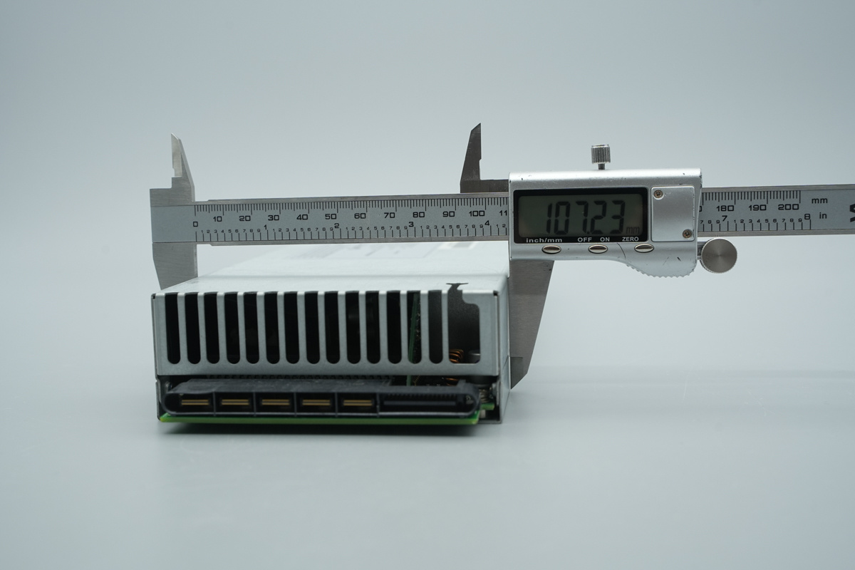
The width of the power supply is about 107mm (4.213 inches).
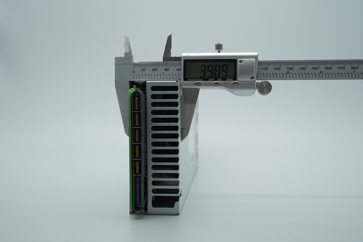
The thickness of the power supply is about 39.9mm (1.571 inches).
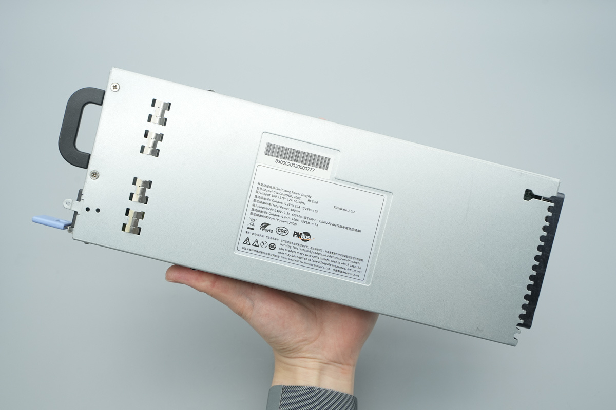
That's how big it is in the hand.
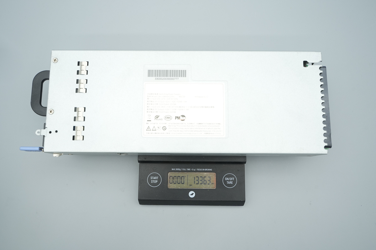
The weight is about 1336g (47.126 oz).
Teardown
Having examined the exterior of the GreatWall server power supply, let's move on to the teardown to explore its internal architecture and components.
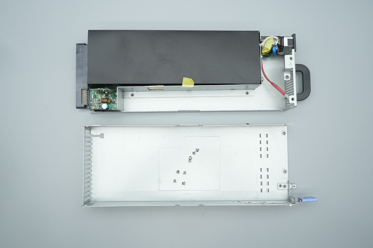
First, we remove the fixing screws and open the casing, revealing the internal power module.
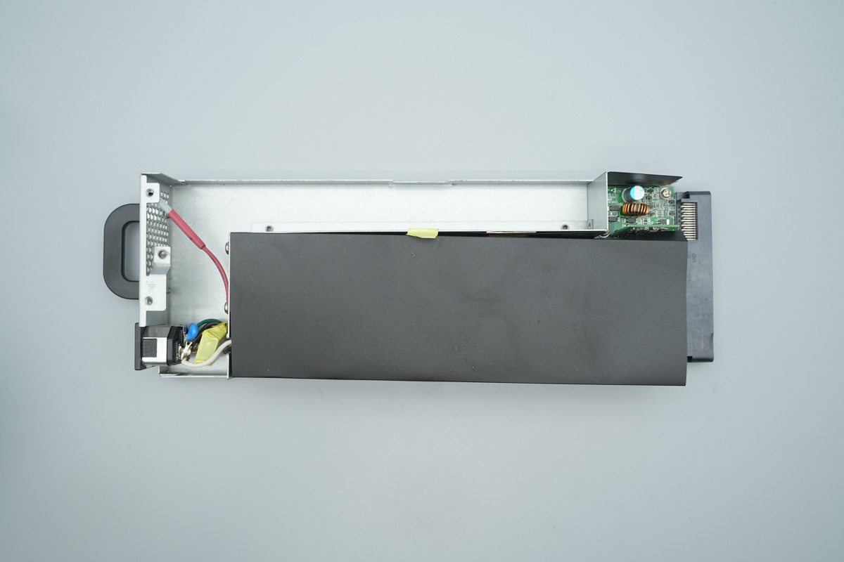
The power module is wrapped with Mylar sheet for insulation.
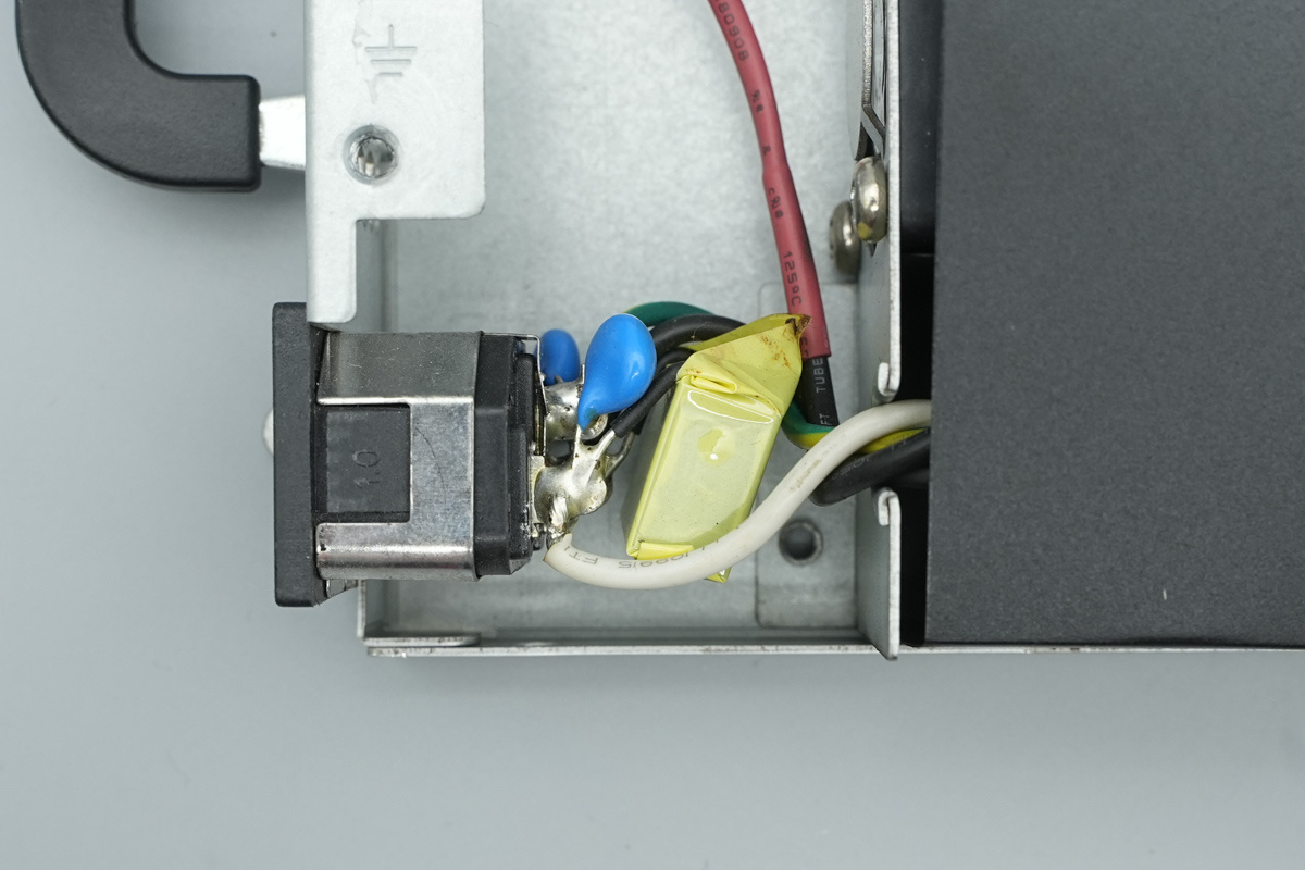
The input end is equipped with safety X2 caps and blue Y-caps.
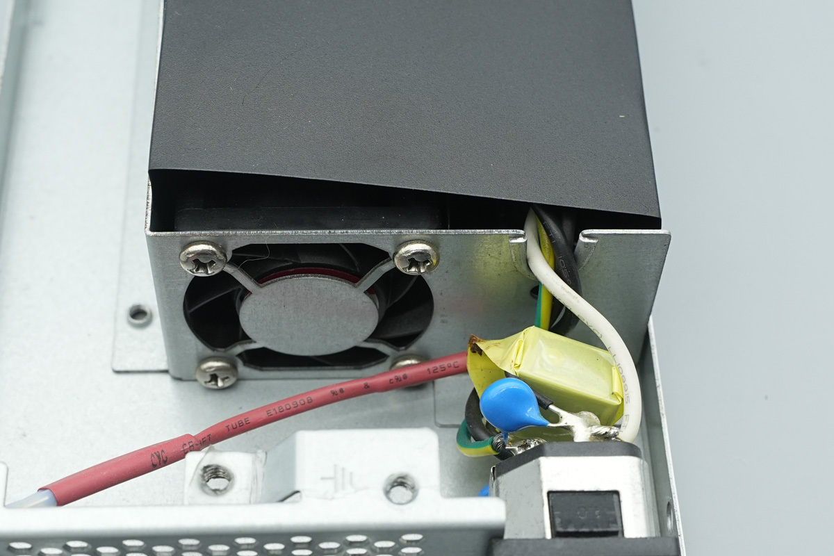
A cooling fan is installed inside the internal casing.

The Mylar sheet is secured with adhesive tape.
The PCBA module is fastened inside the chassis with screws.
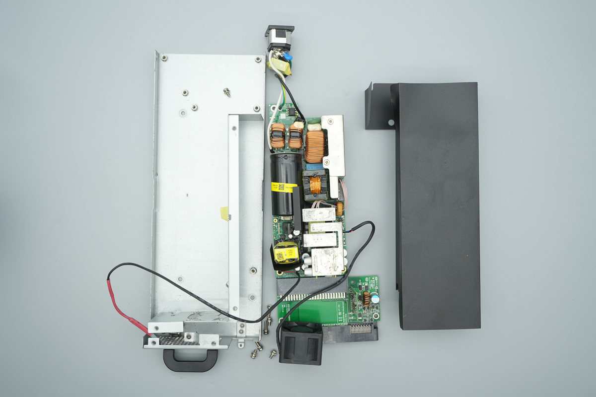
Unscrew the fixing screws and take out the PCBA module.
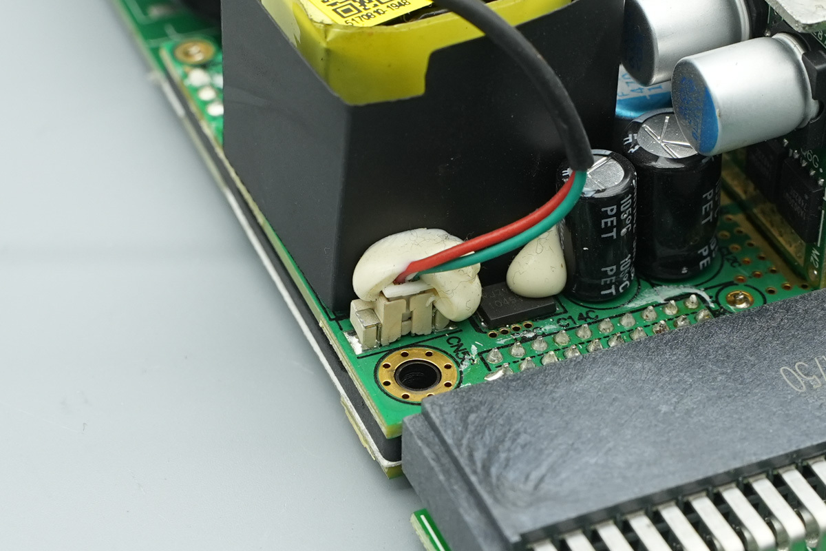
The LED indicator is connected to the PCBA module.
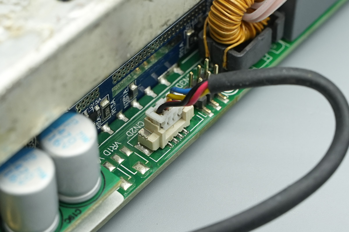
The cooling fan is connected to the PCBA module.
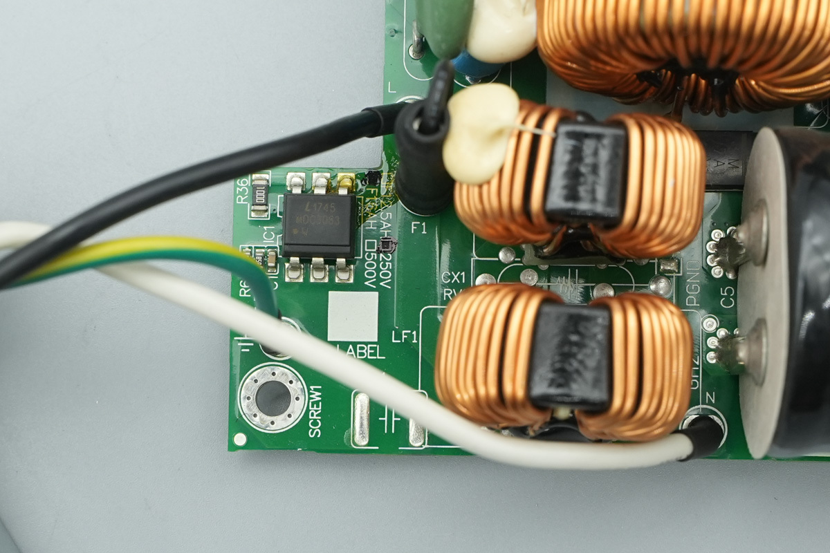
The input wires are connected via soldering.
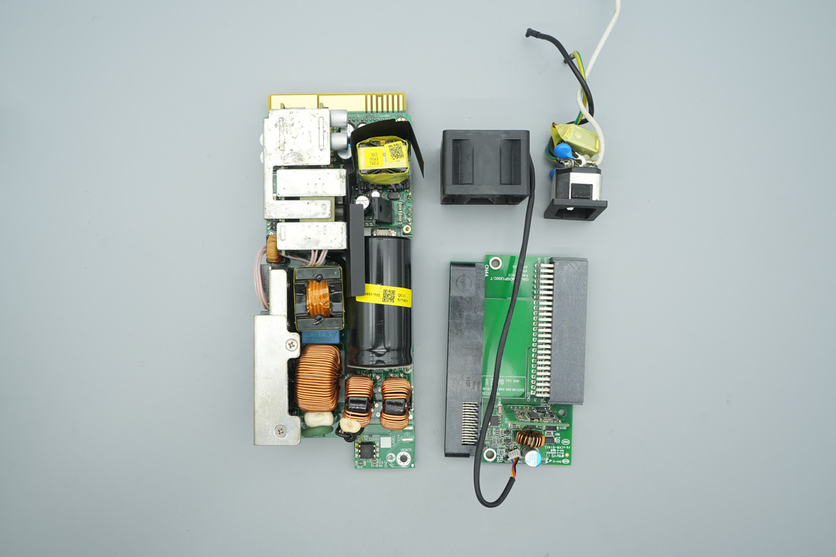
The internal PCBA module, adapter PCB, IEC input socket, and cooling fan.
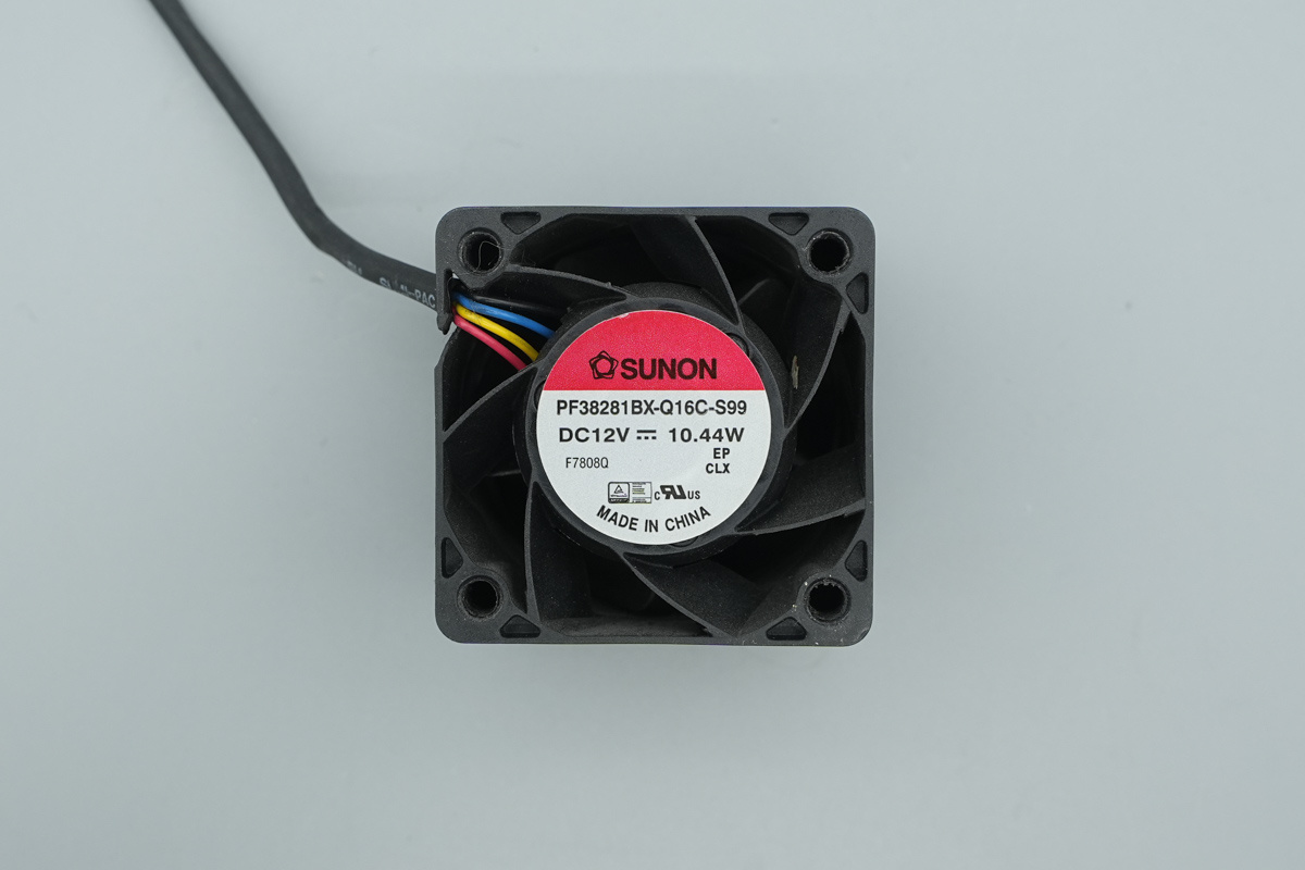
The cooling fan is from SUNON, model PF38281BX-Q16C-S99, spec 12V10.44W.
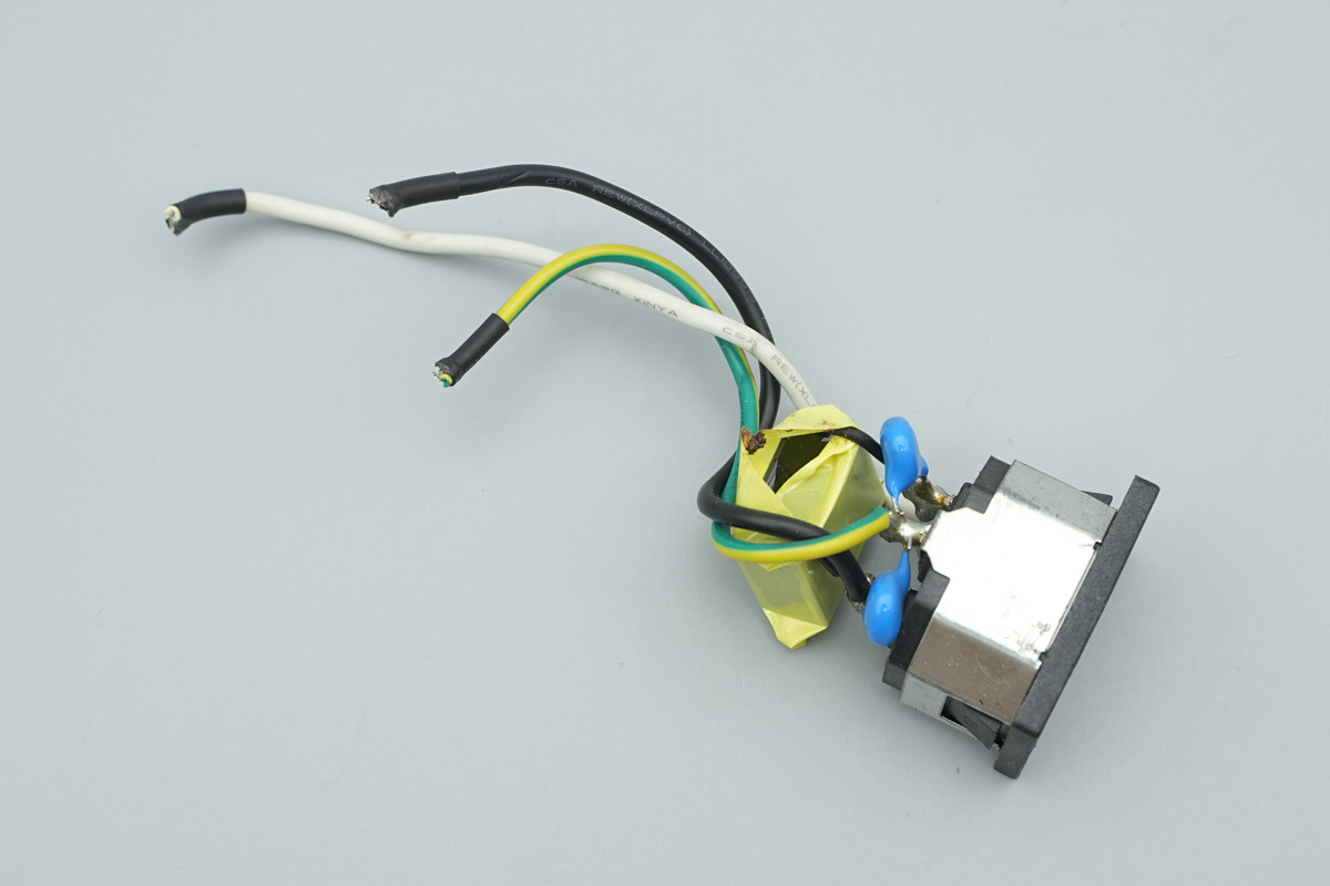
The IEC power socket is connected to wires via soldering.
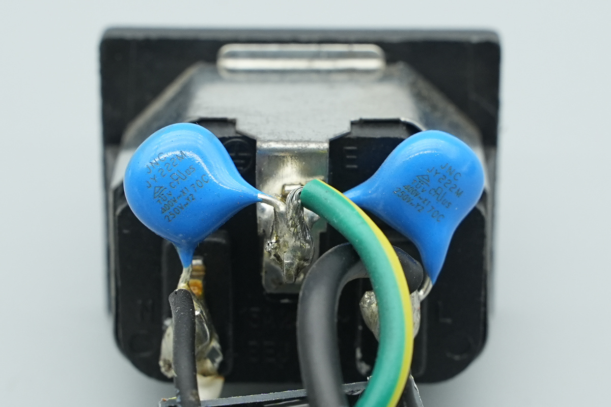
The blue Y-cap is from JNC, model JY222M.
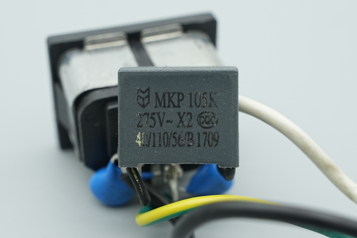
The safety X2 cap,spec 1μF.
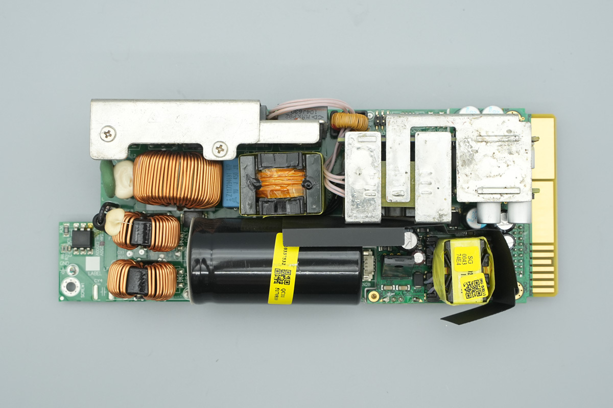
The front of the PCBA module shows a common-mode choke at the bottom-left, a heatsink and PFC boost choke along the upper-left side, a resonant choke, current transformer, and resonant cap in the middle, high-voltage filter caps along the bottom, copper busbars soldered on the upper-right to connect the output, and a standby power chip and standby power transformer on the lower-right.
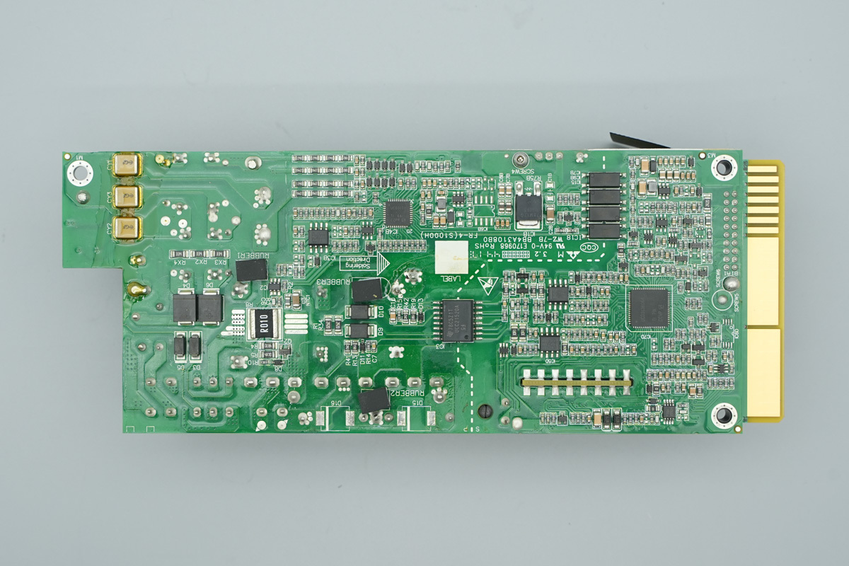
The back of the PCBA module features a rectifier MOSFET, current sense resistor, PFC controller, operational amplifiers, gate drivers, voltage regulator chips, isolated drivers, LLC controller, and synchronous step-down chips.
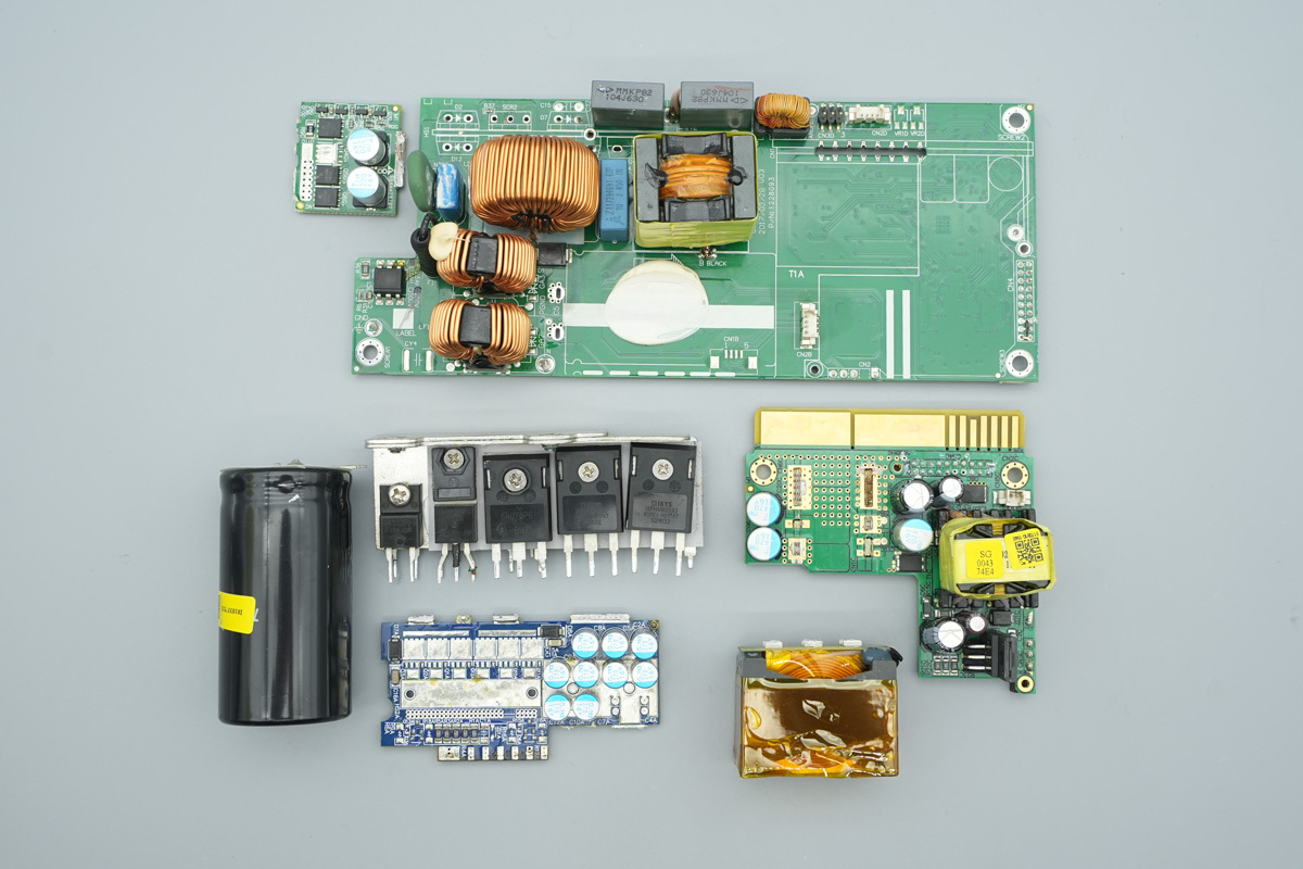
The high-voltage filter caps, heatsinks, transformers, synchronous rectifier PCB, and output PCB are desoldered and removed to continue the teardown.
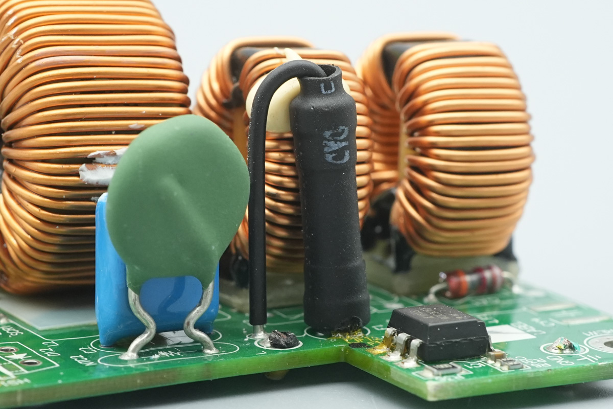
The input fuse is rated at 16A 250V and covered with heat-shrink tubing for insulation.
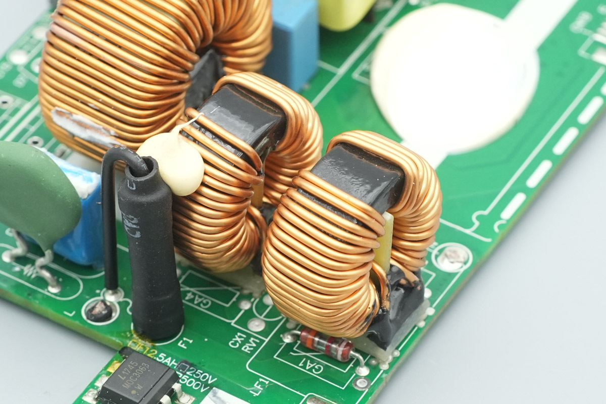
The common-mode choke is wound with enameled wire, with Bakelite PCB insulation provided internally and at the bottom.
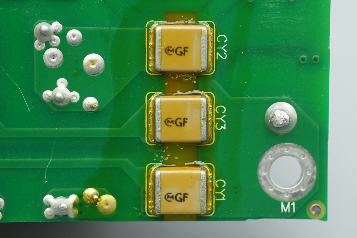
The SMD Y-cap is from Holy Stone, coated with conformal coating for protection.
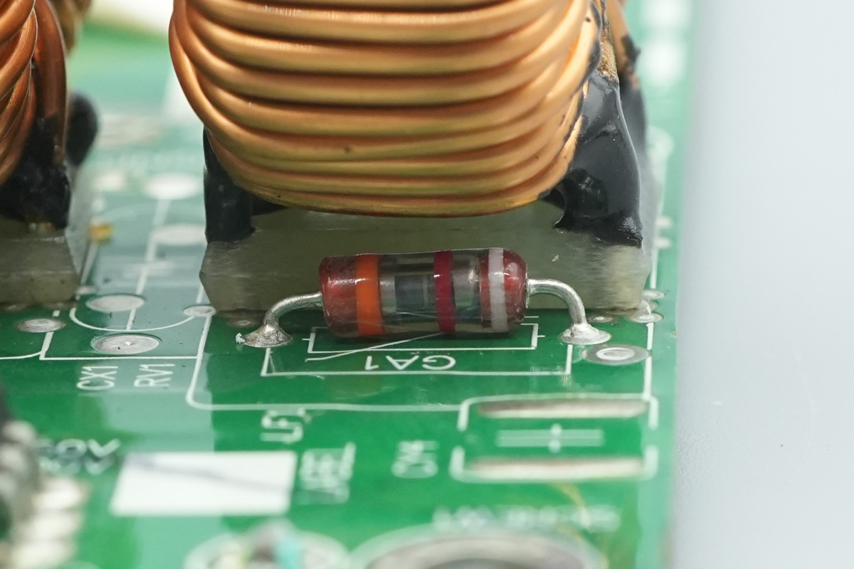
A gas discharge tube is positioned beside the common-mode choke.
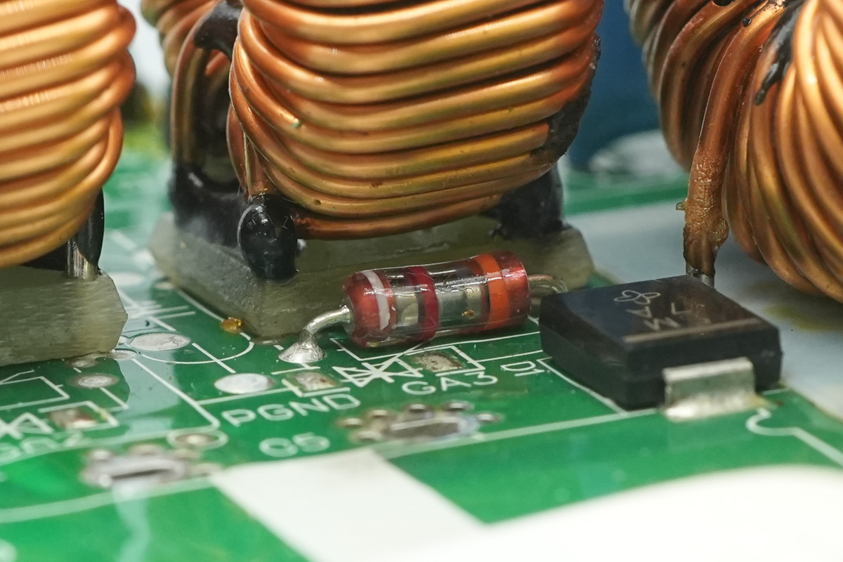
Another one is also located near the second common-mode choke.
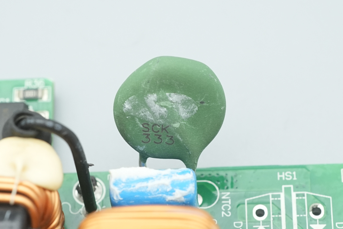
The NTC thermistor, model SCK333.
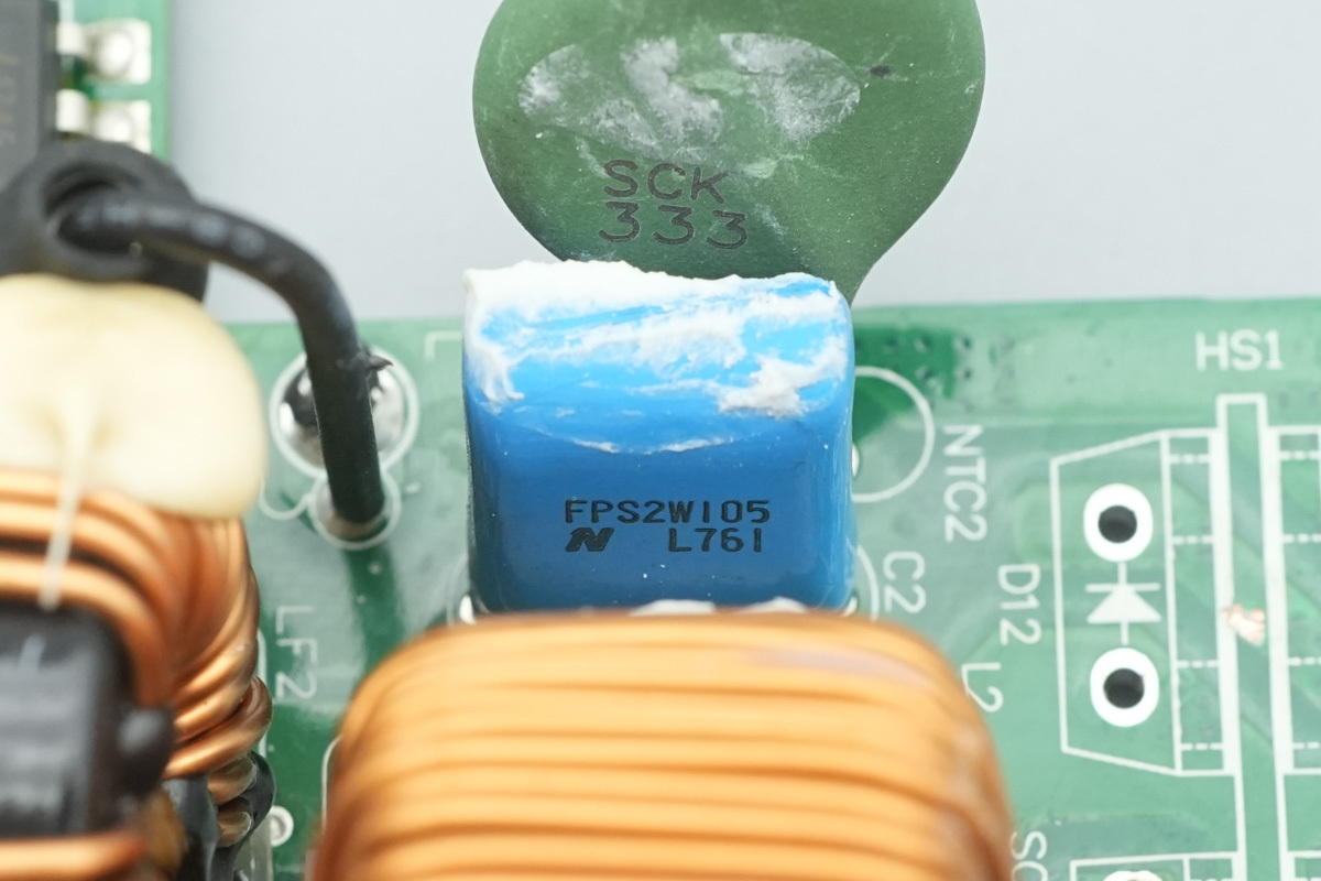
The film filtering cap is from Nitsuko, FPS series, model FPS22W105K, spec 1μF 450V.
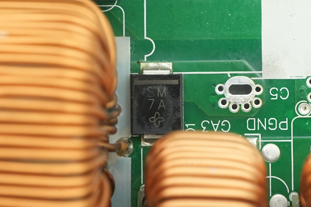
The bypass diode is from VISHAY, marked SM, model S3M, rated at 1000V 3A, and packaged in an SMC package.
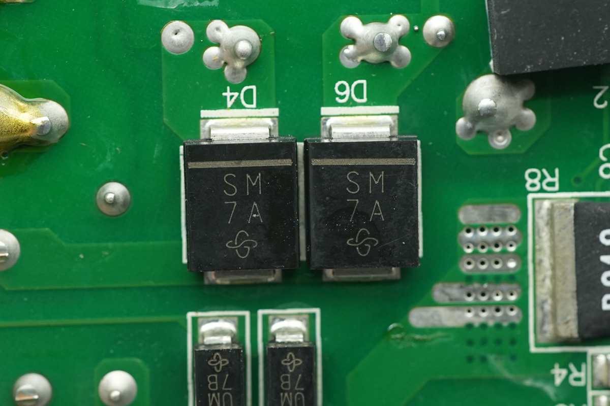
Two SMD diodes share the same model.
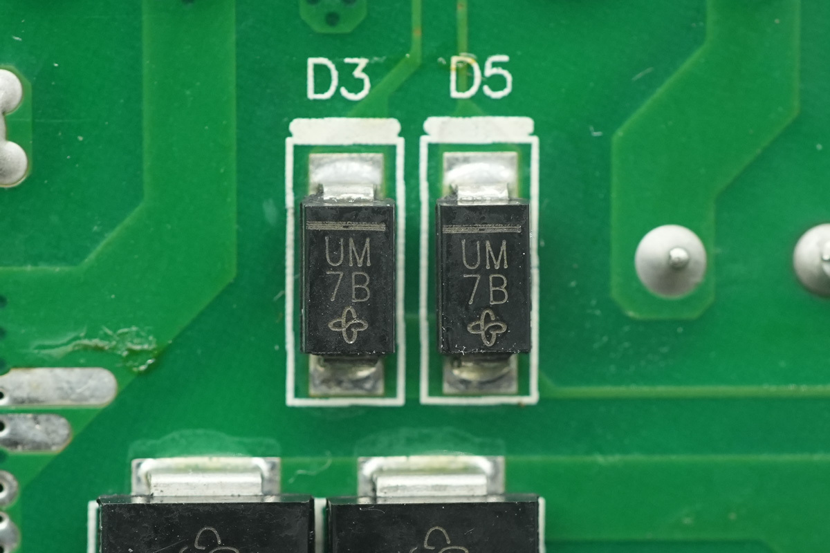
The diode is from VISHAY, marked UM, model US1M. It is an ultra-fast recovery diode rated at 1000V 1A, packaged in an SMA package.
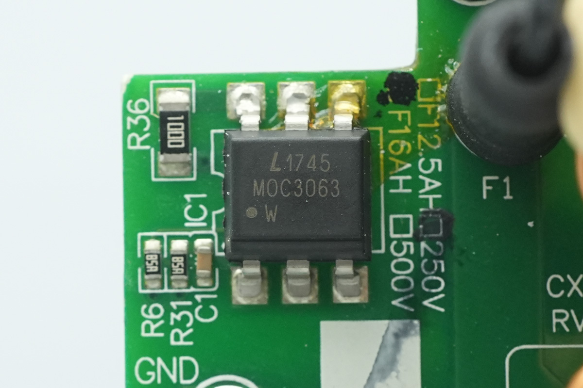
The optocoupler is from LITEON, model MOC3063, in a SMD package.
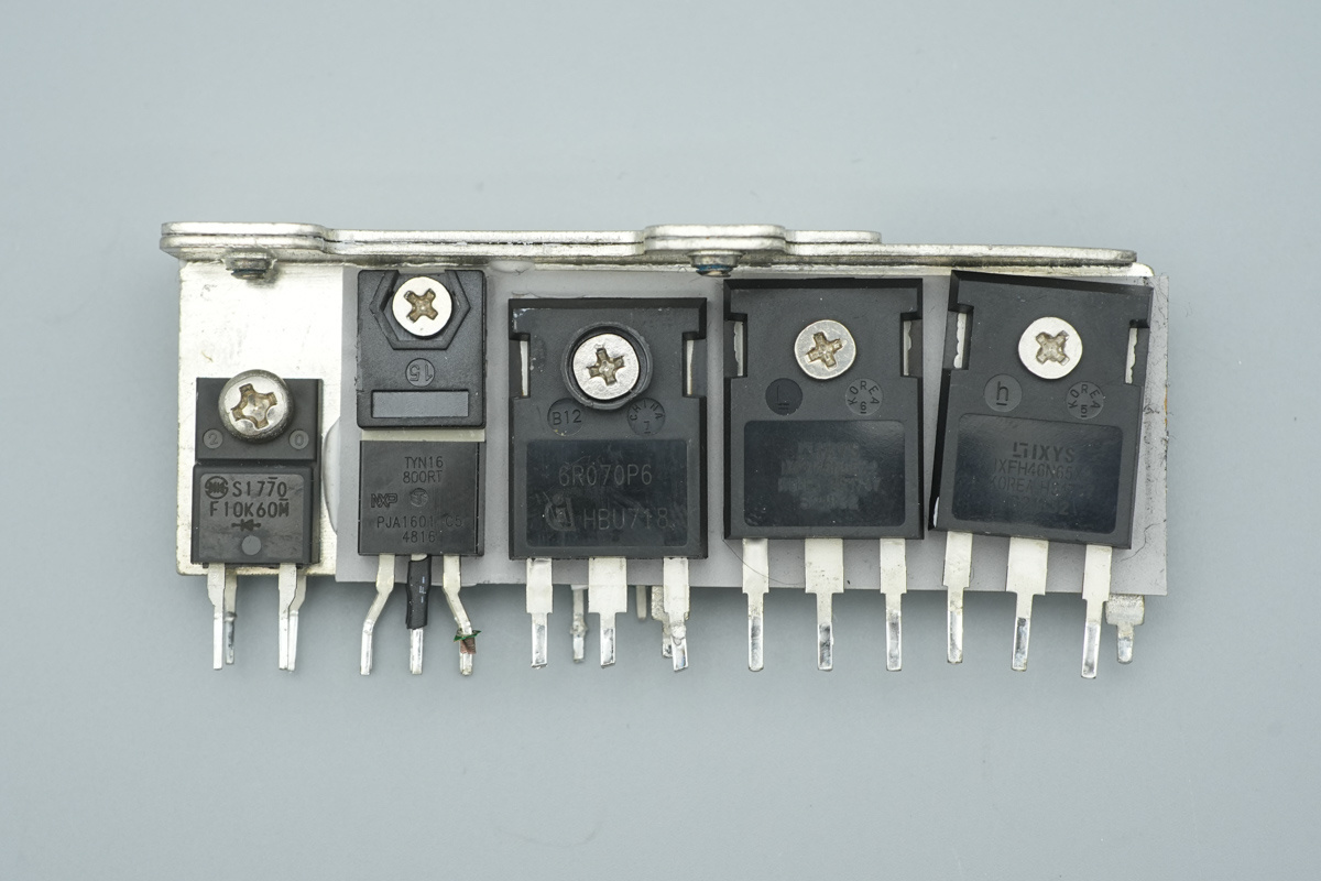
The heatsink secures the rectifier MOSFET, thyristor, PFC MOSFET, and LLC MOSFET.
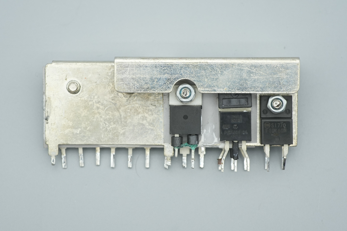
The other side secures the PFC rectifier MOSFET, thyristor, and rectifier MOSFET.
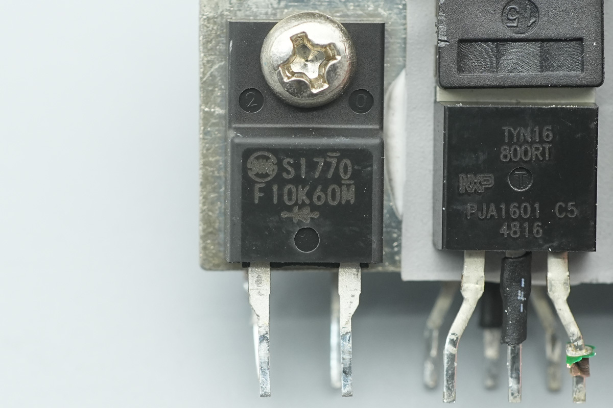
The rectifier MOSFET is from SHINDENGEN, model SF10K60M. It is a fast recovery diode rated at 600V 10A, packaged in an FTO-220AG package.
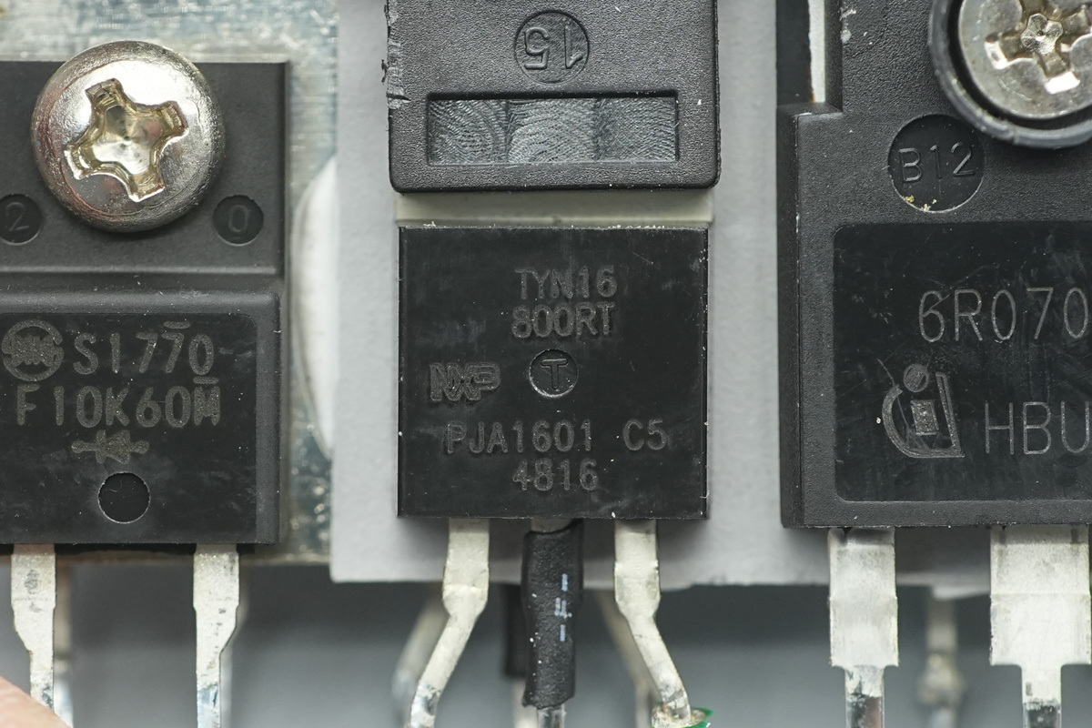
The thyristor is from WeEn, model TYN16-800RT, rated at 800V 16A, and packaged in a TO-220 package.
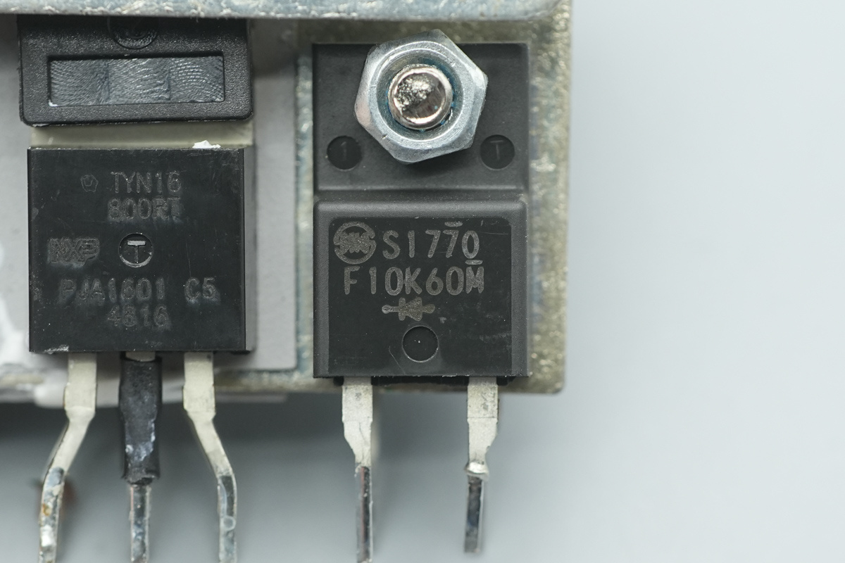
The other rectifier MOSFET shares the same model.
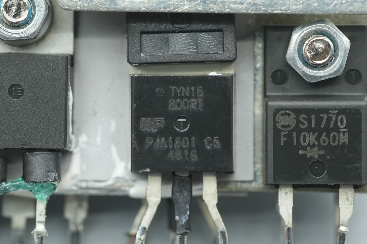
The other thyristor shares the same model.
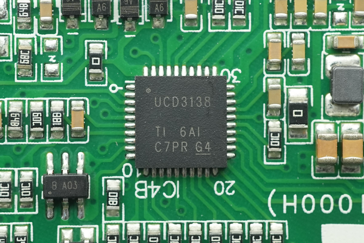
The PFC controller is from TI, model UCD3138, a highly integrated digital power controller. It features a high-performance 32-bit processor, 32KB of integrated flash memory, and supports I2C, PMBus, and UART interfaces. It is designed for power supply, telecom rectifier, power factor correction, and DC-DC module applications, and it is housed in a QFN40 package.
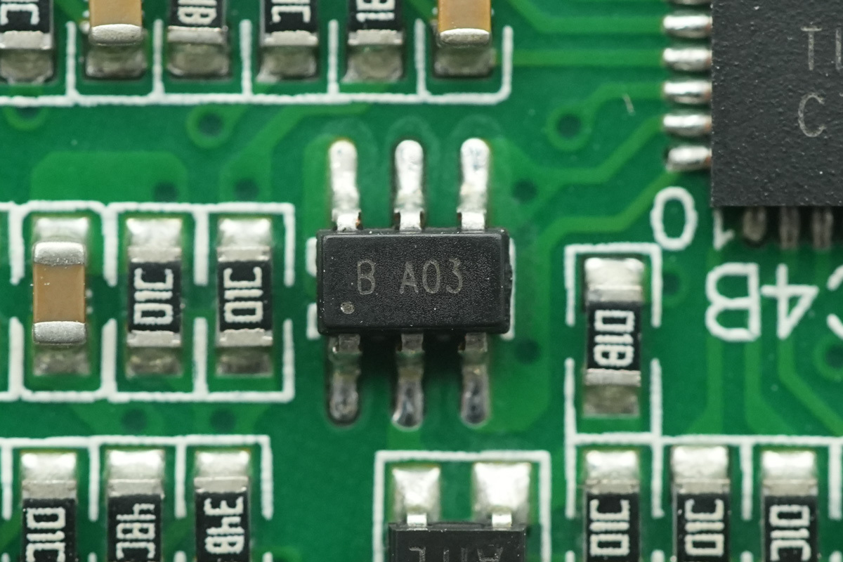
The chip,marked B A03.
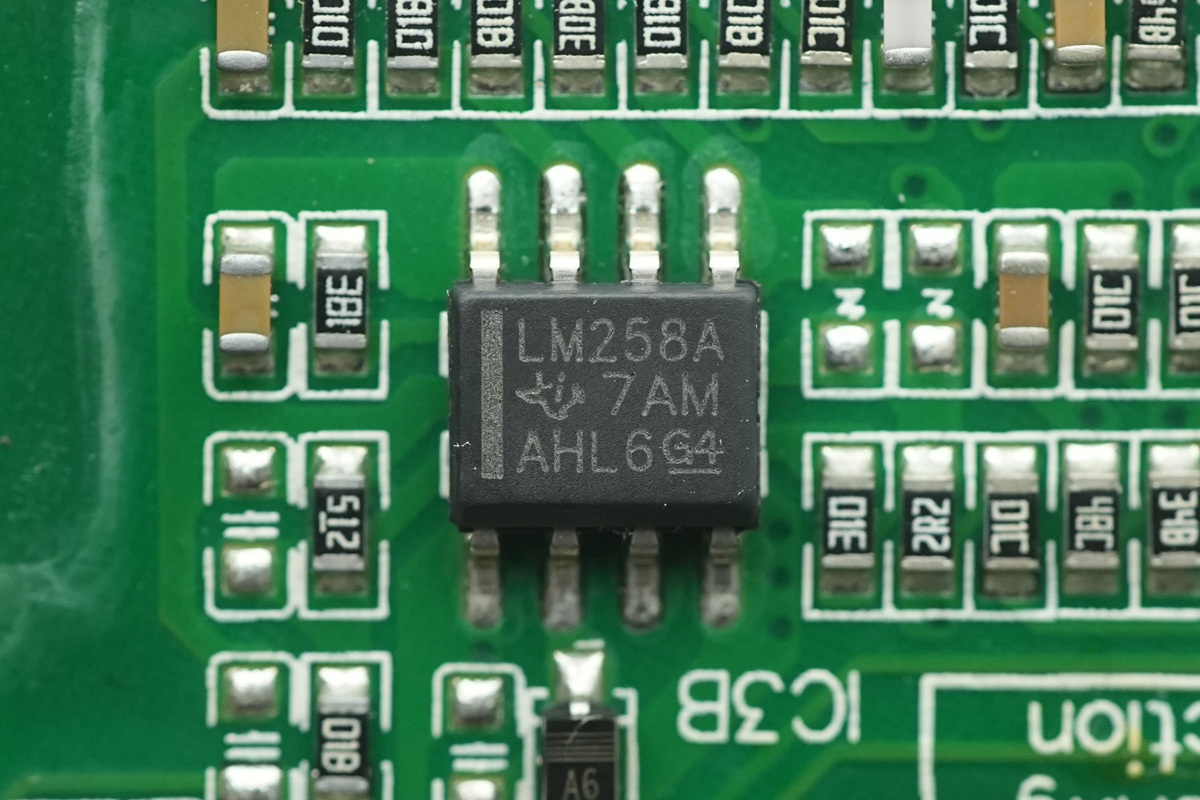
The operational amplifier is from TI, model LM258A, a standard dual operational amplifier that supports a 30V operating voltage, housed in an SOIC8 package.
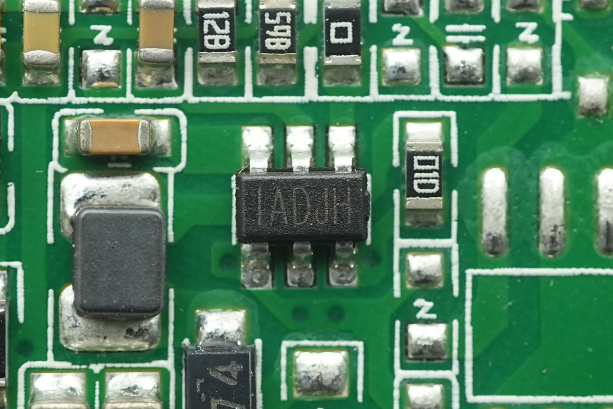
The step-down chip is from MPS, marked IADJ, model MP1470. It is a synchronous buck converter supporting a 16V input voltage and 2A output current, featuring an integrated switch and housed in a TSOT23-6 package.
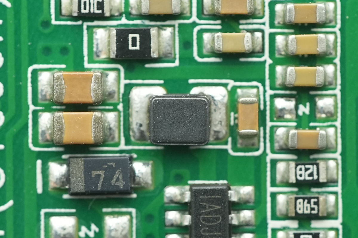
The paired step-down choke.
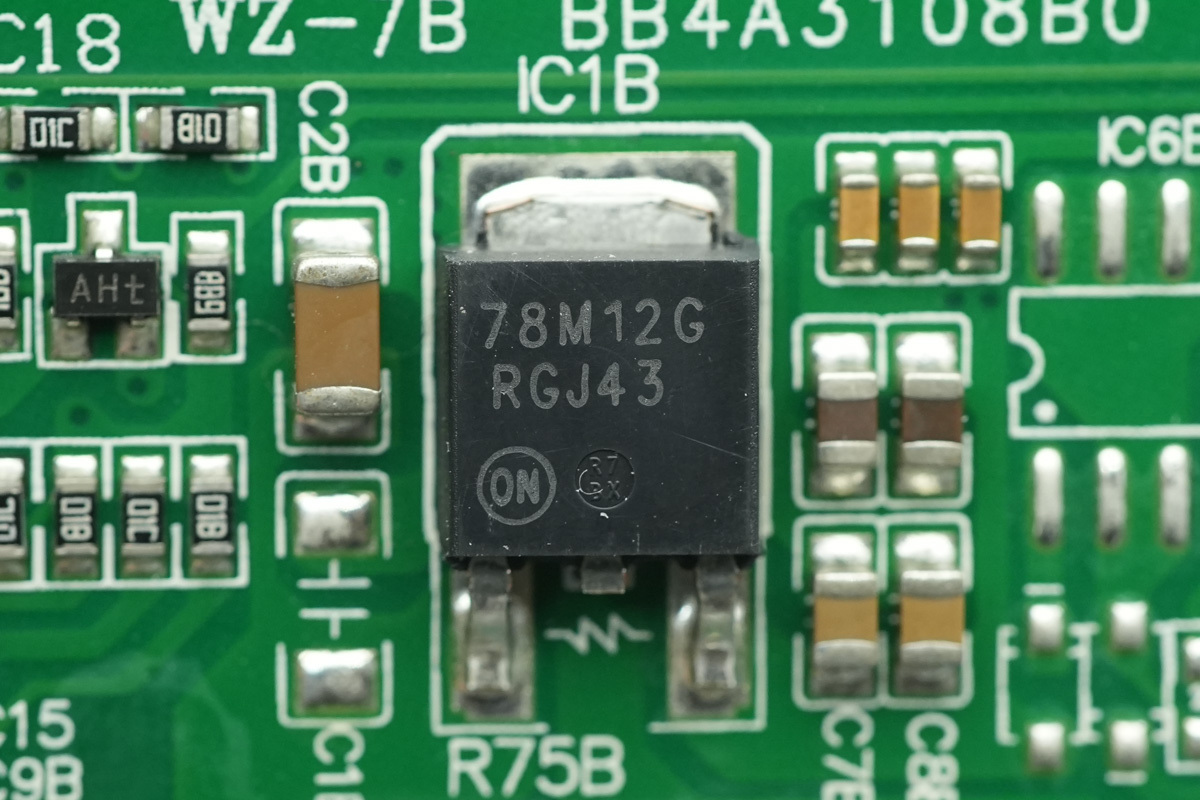
The voltage regulator chip is from onsemi, model MC78M12, supporting an input voltage up to 35V, with an output voltage of 12V and an output current of 500mA, housed in a DPAK-3 package.
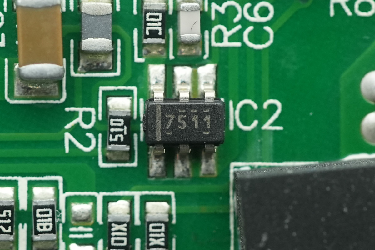
The PFC MOSFET driver is from TI, model UCC27511, a single-channel high-speed driver featuring a 4A peak source and 8A peak sink current, packaged in an SOT-23 package.
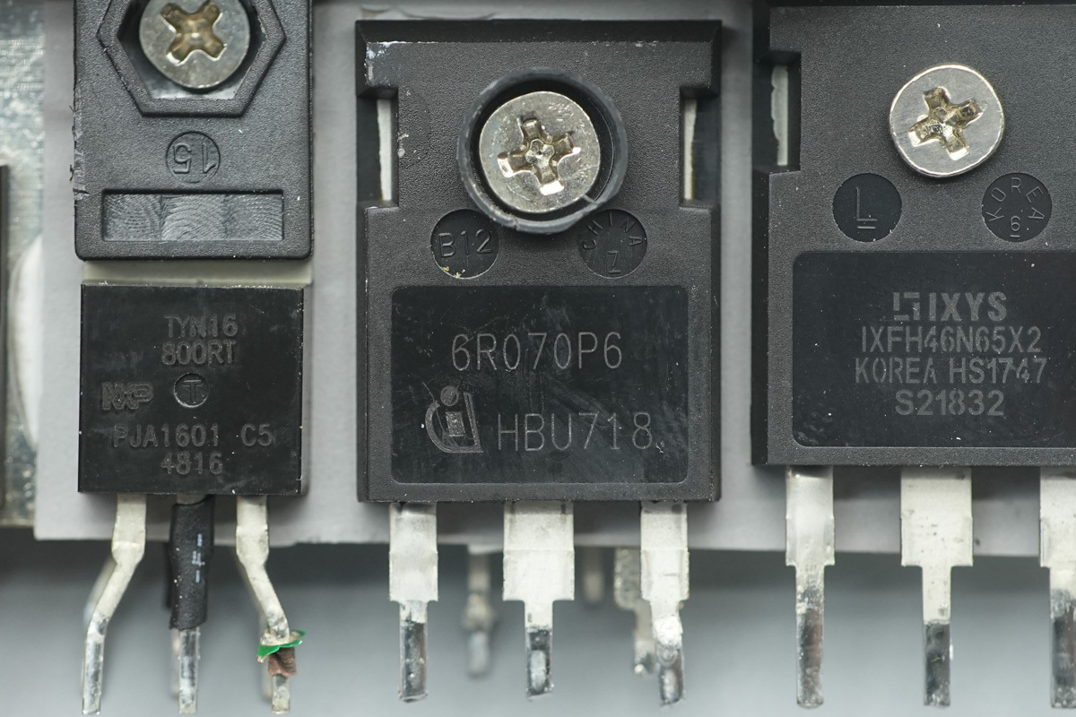
The PFC MOSFET is from Infineon, marked 6R070P6, model IPW60R070P6, NMOS, 650V and 70mΩ, in a TO-247 package.
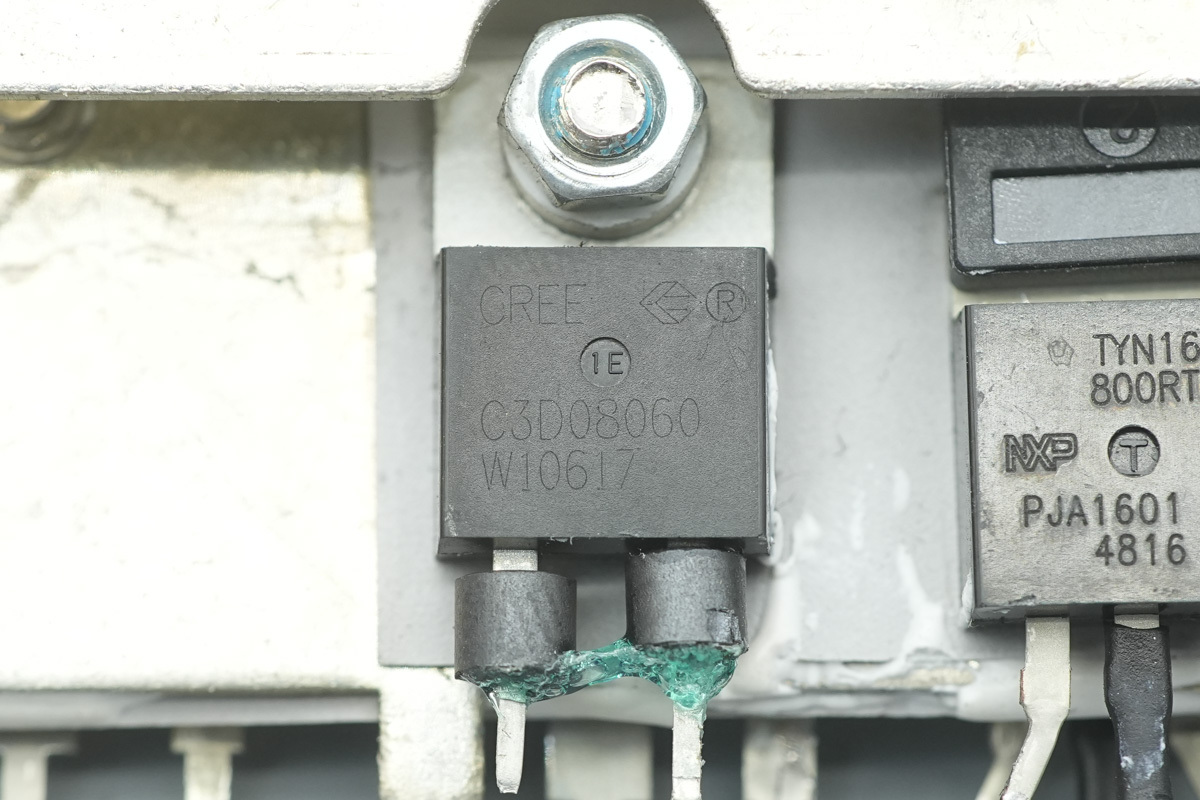
The PFC rectifier MOSFET is from Wolfspeed, model C3D08060A, a SiC Schottky diode rated at 600V and 8A, housed in a TO-220-2 package.
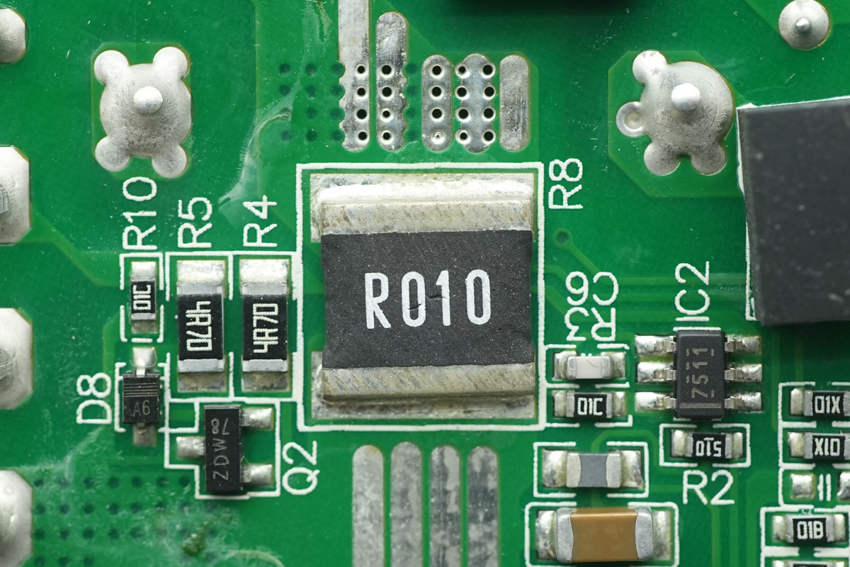
A 10mΩ current sense resistor is used to detect the PFC MOSFET current.
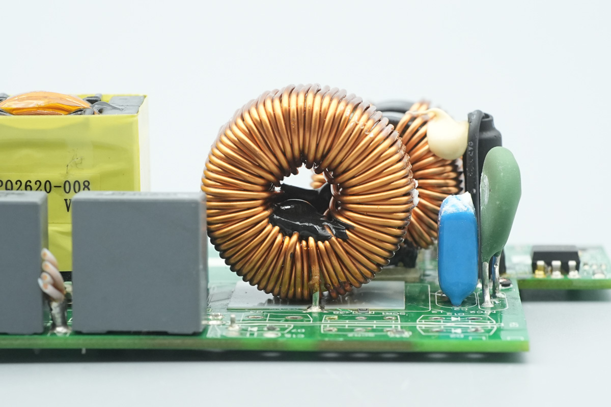
The PFC boost choke is wound with enameled wire, with a plastic insulation sheet placed at the bottom.
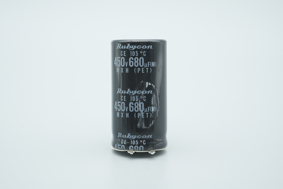
The high-voltage filter cap is from Rubycon, spec 450V 680μF.
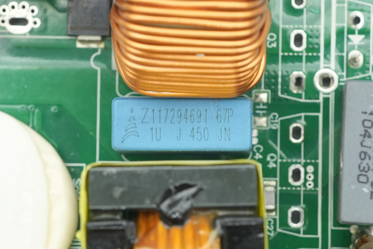
The film filtering cap is from TDK, spec 1μF450V.
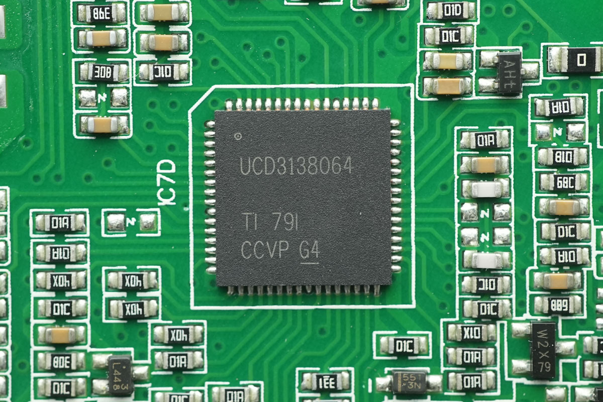
The LLC controller is from TI, model UCD3138064, a digital power controller featuring 64kB of integrated flash memory, SPI and I2C interfaces. It supports phase-shifted full-bridge, single and interleaved PFC, bridgeless PFC, hard-switched full-bridge and half-bridge, as well as half-bridge and full-bridge LLC applications, housed in a VQFN64 package.
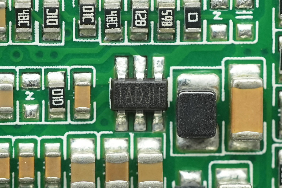
The synchronous step-down chip is the MPS MP1470.
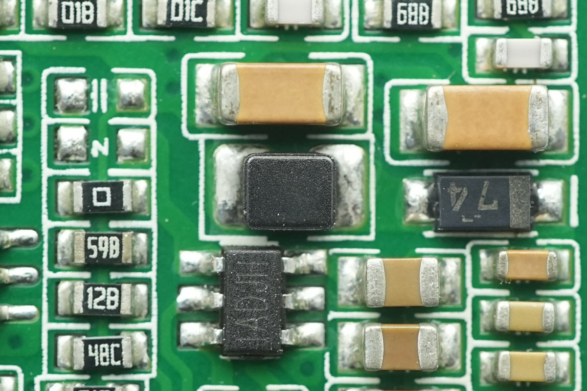
The paired step-down choke.
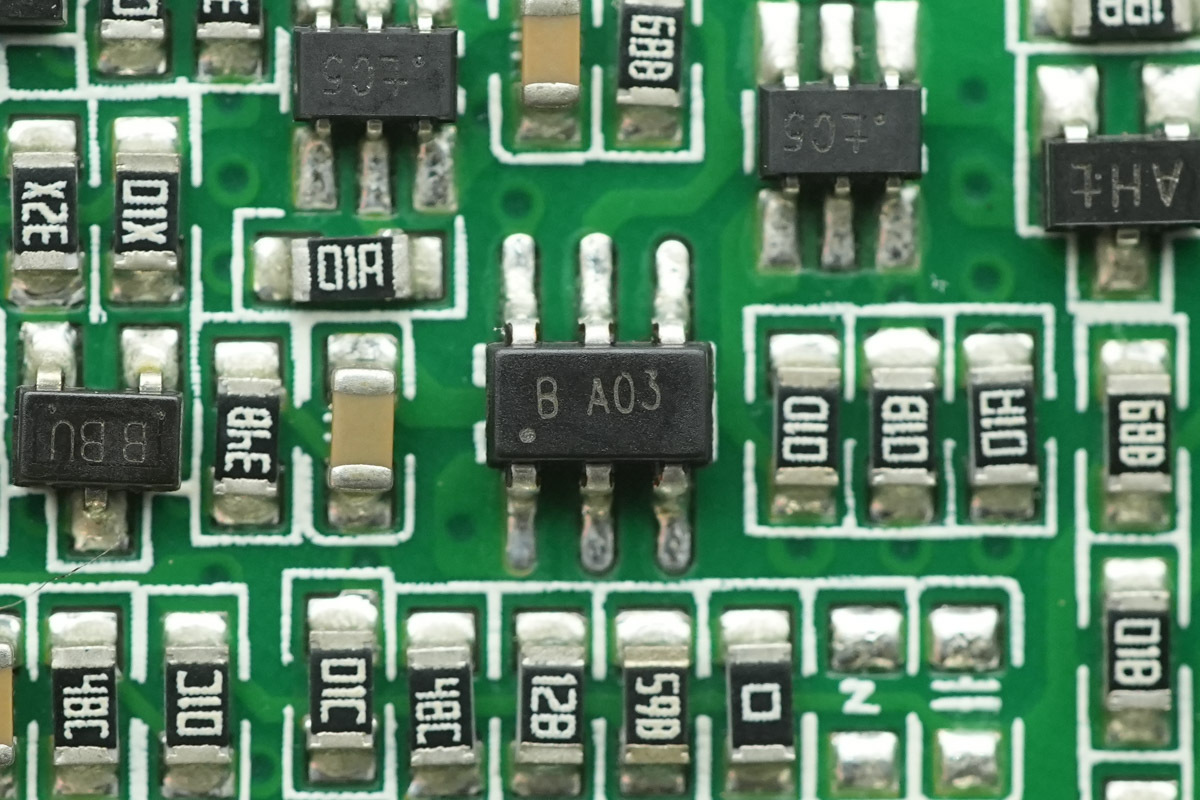
The chip, marked B A03.
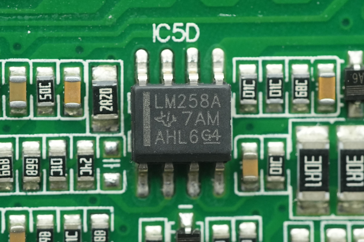
The operational amplifier is TI LM258A.
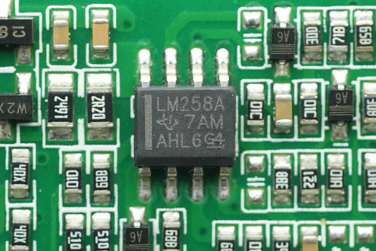
The other one shares the same model.
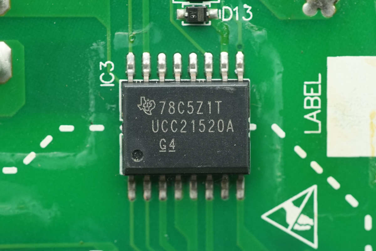
The isolated driver is from TI, model UCC21520A, a dual-channel isolated driver supporting a 4A source and 6A sink current, featuring 5.7kVrms isolation capability, 3-18V input voltage range, 25V drive voltage, andUVLO protection, housed in an SOIC16 package.
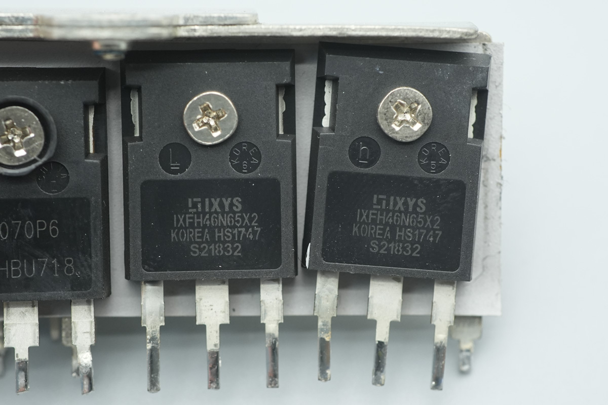
The LLC MOSFET is from Littelfuse, model IXFH46N65X2, NMOS, 650V and 69mΩ, housed in a TO-247 package.
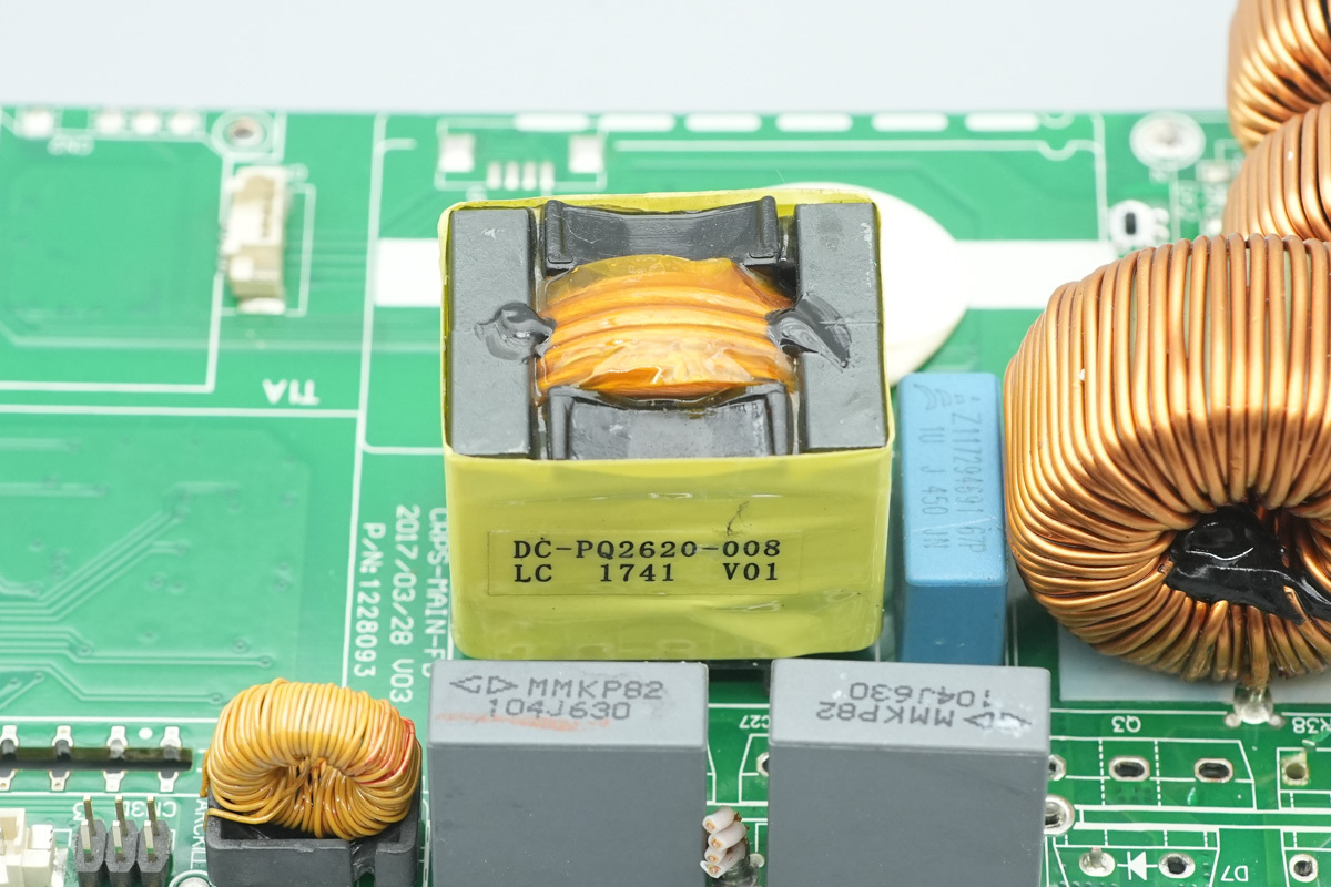
The LLC resonant choke is wound with Litz wire.
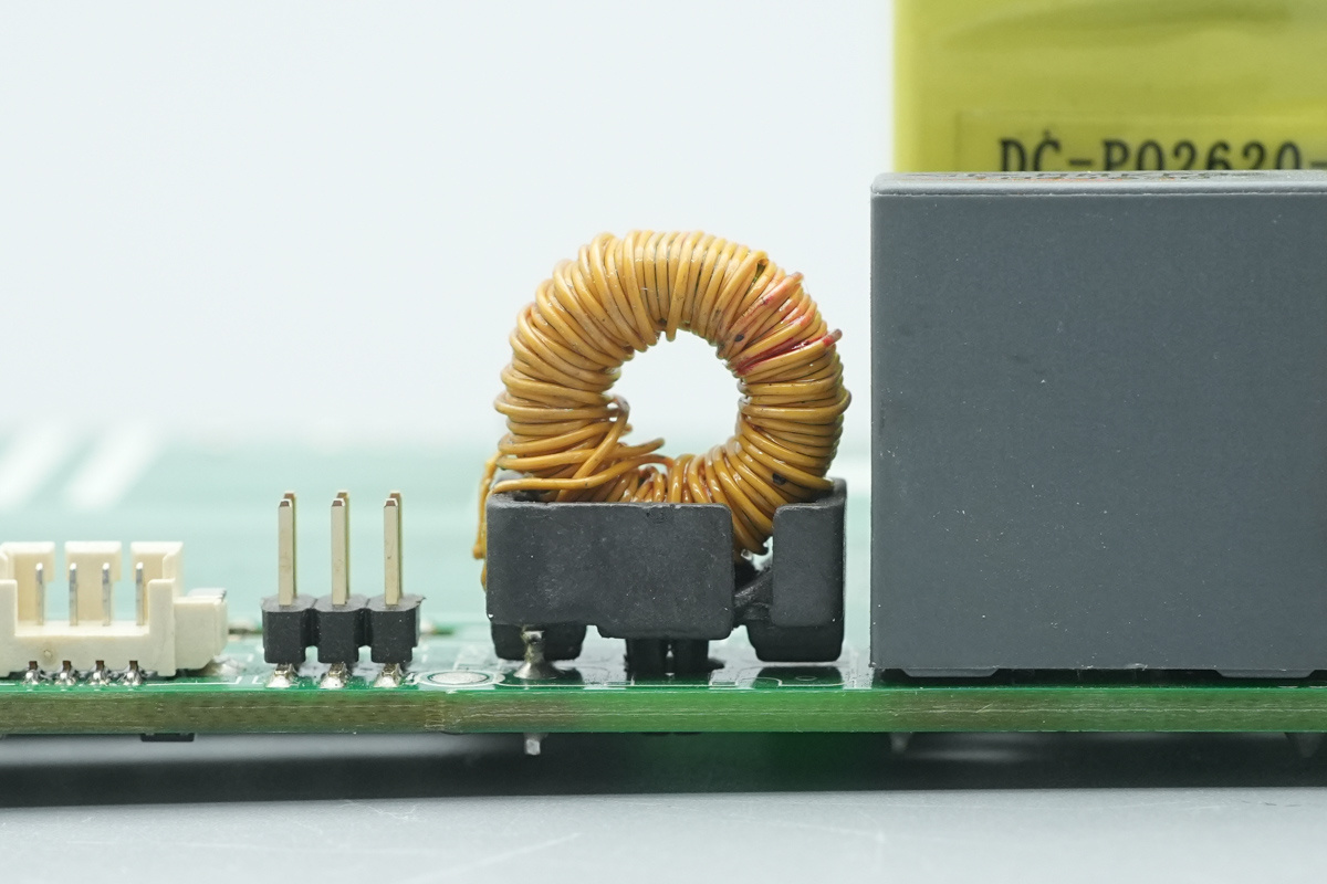
The current transformer is wound with insulated wire.
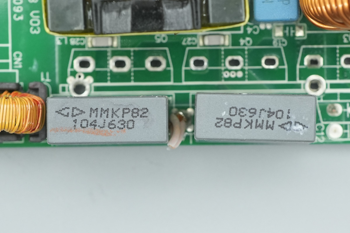
The resonant cap is from Faratronic, spec 0.1μF630V.
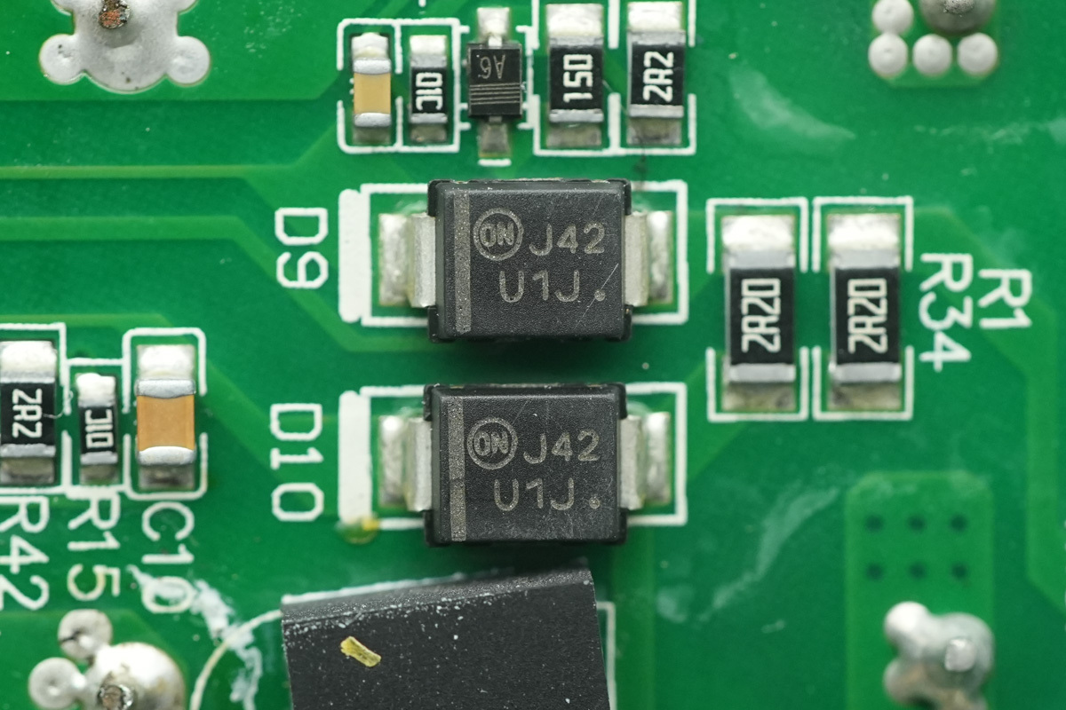
The two fast recovery diodes are from onsemi, marked U1J, model MURS160. They are ultra-fast recovery diodes rated at 600V and 1A, packaged in an SMB package.
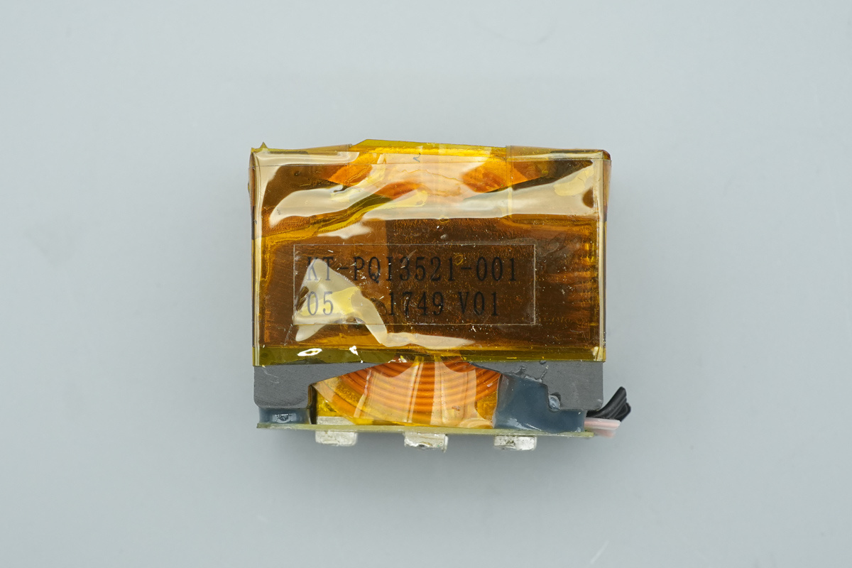
The transformer primary is wound with Litz wire, the secondary is soldered with copper foils, and the magnetic core is wrapped with high-temperature adhesive tape for insulation.
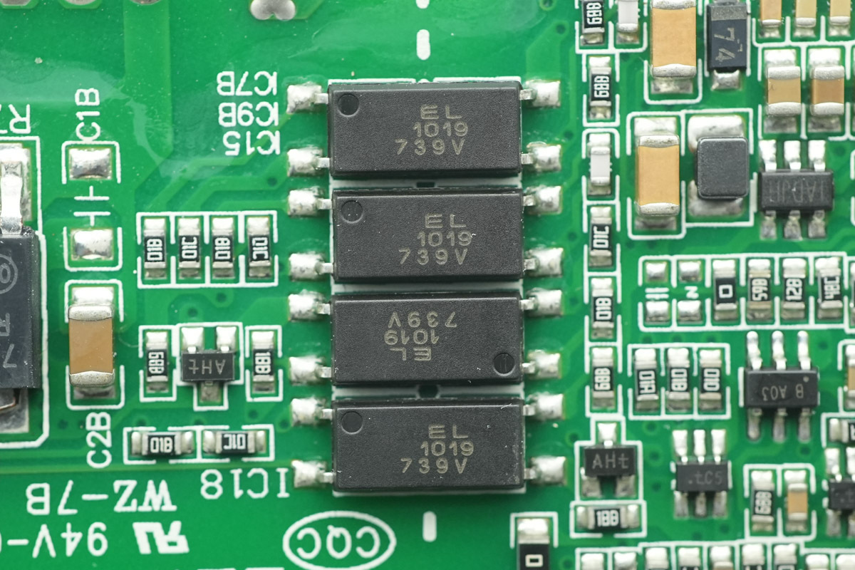
The Everlight EL1019 optocoupler is used for isolated communication between the primary and secondary sides.
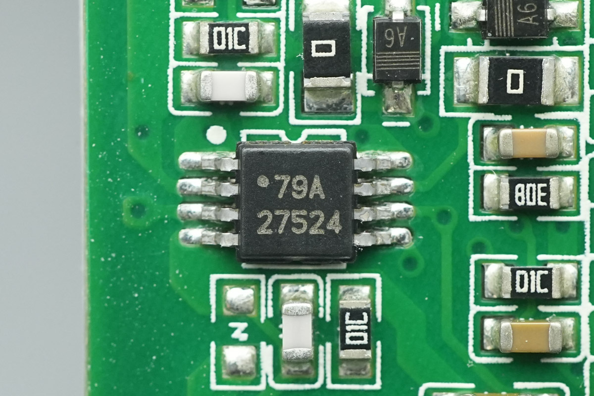
The gate driver is from TI, model UCC27524, a dual-channel 5A high-speed low-side gate driver with negative input voltage capability, housed in an HVSSOP8 package.
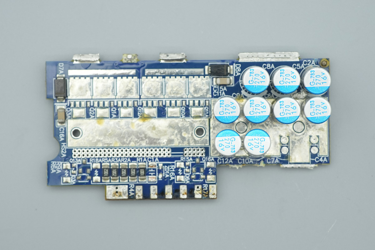
The synchronous rectifierPCB is connected via soldering, with filtering caps mounted on one side.
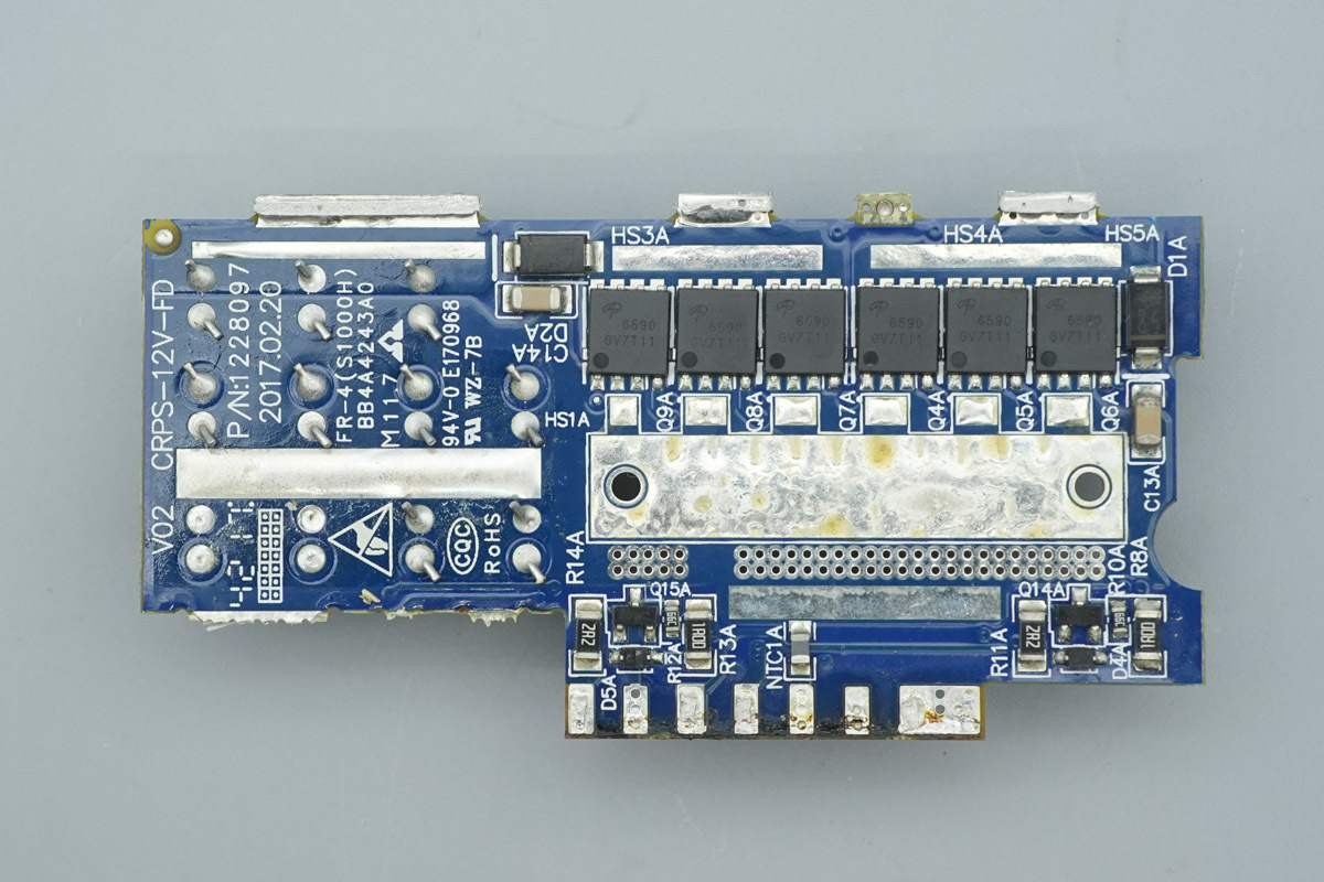
The other side features synchronous rectifier MOSFETs.
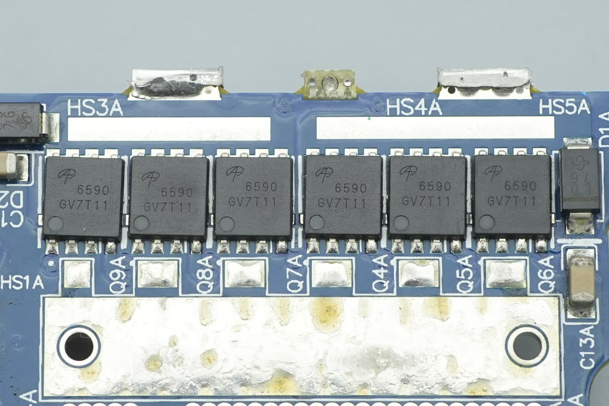
The synchronous rectifier MOSFET is from AOS, model AON6590, NMOS, 40V and 0.78mΩ, housed in a DFN5x6 package.
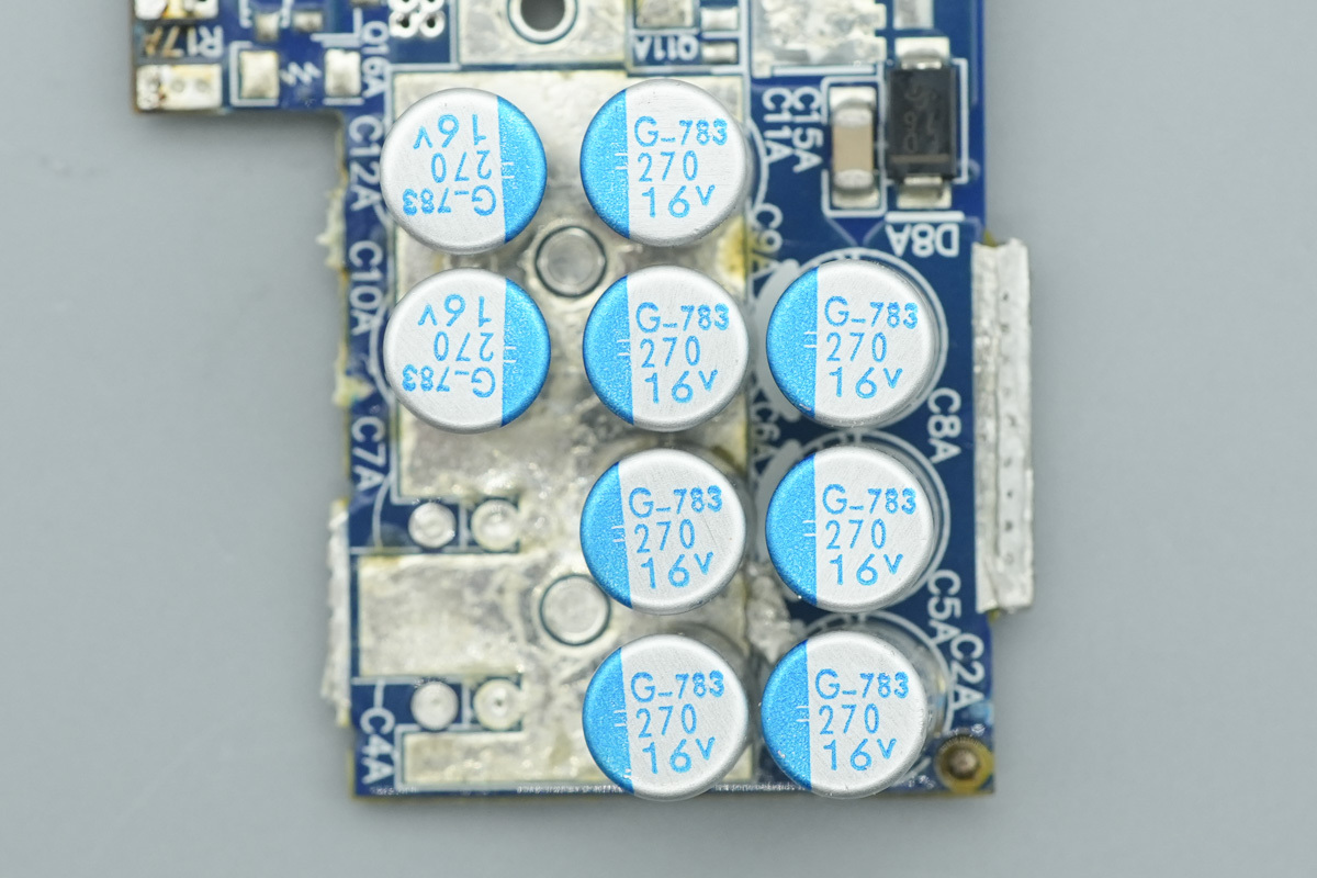
The filtering caps are from NCC, PSG series conductive polymer aluminum solid electrolytic caps, featuring ultra-low ESR and high ripple current characteristics, with a rated lifespan of 15,000 to 20,000 hours at 105°C. Each is rated at 270μF 16V, and nine of these are used for output filtering.
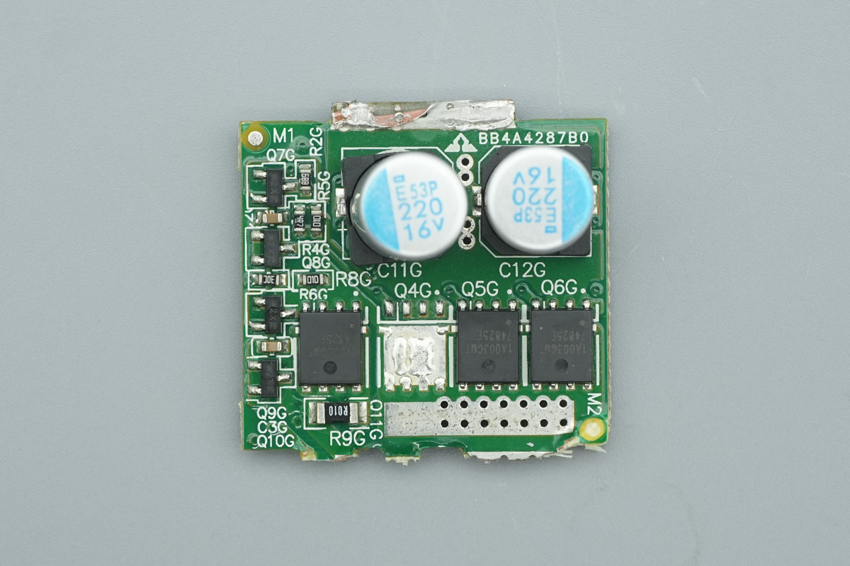
The output control PCB features filtering caps and output control MOSFETs.
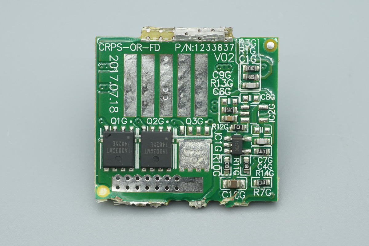
The back is populated with two output control MOSFETs.
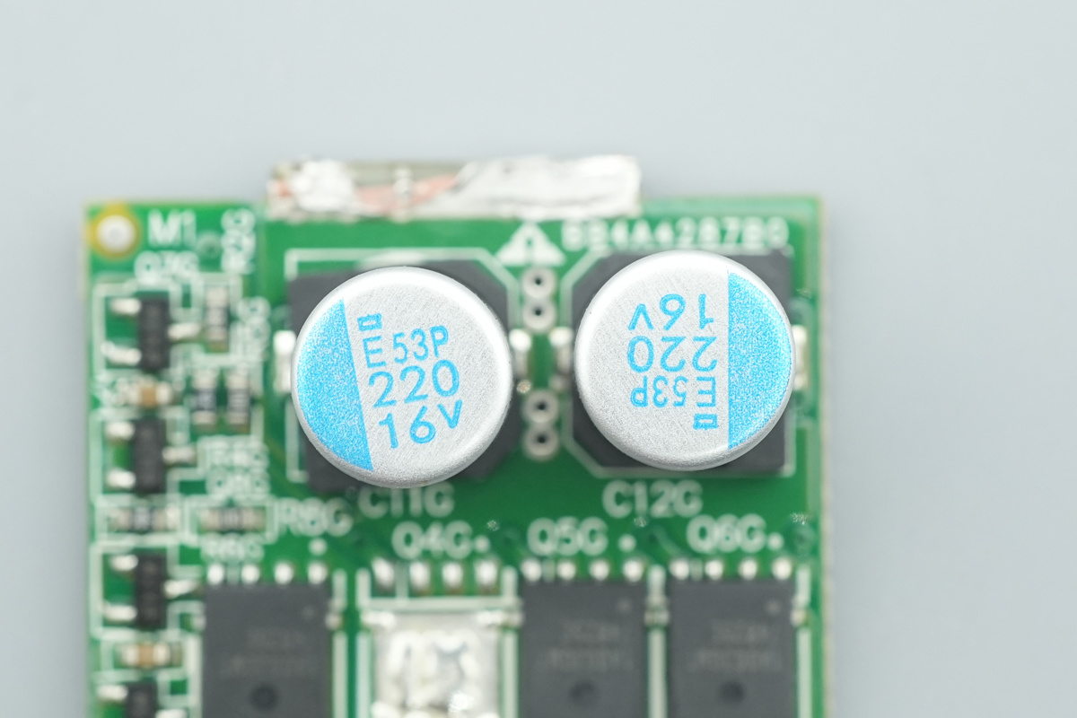
The filtering caps are from NCC, PXE series conductive polymer aluminum solid electrolytic caps, featuring ultra-low ESR and high ripple current characteristics, with a rated lifespan of 15,000 to 20,000 hours at 105°C, and a specification of 220μF and 16V.
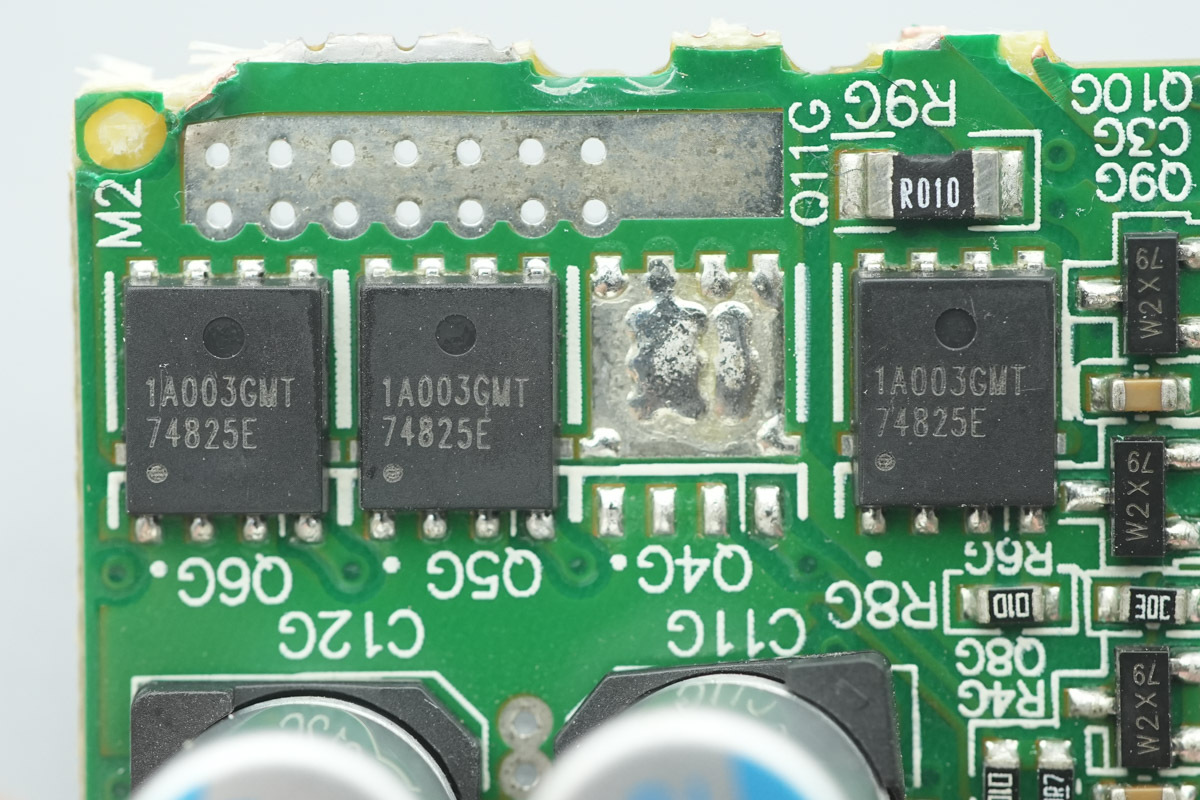
The output VBUS MOSFET is from APEC, model AP1A003GMT, NMOS, 30V and 0.99mΩ, housed in a PMPAK5x6 package.
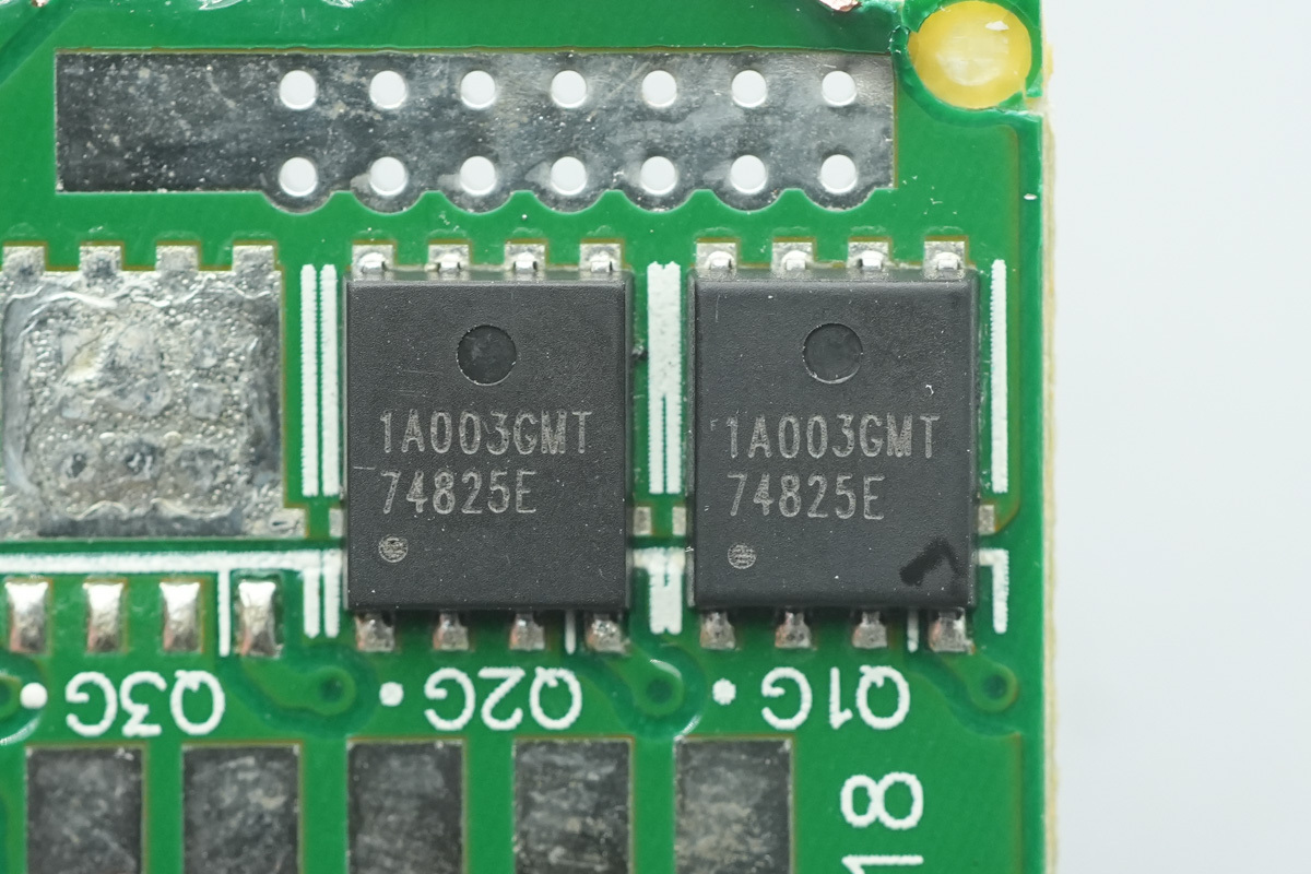
The two MOSFETs on the other side share the same model.
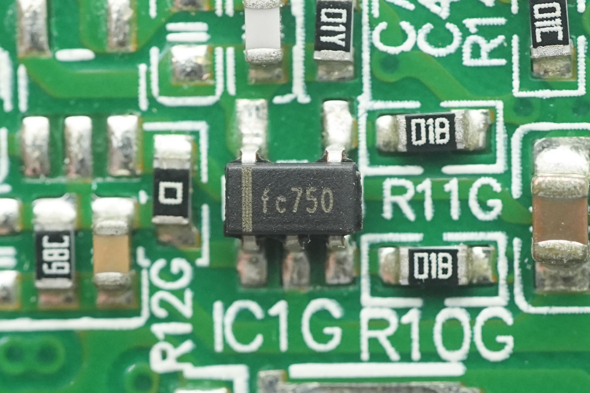
A chip, marked FC750, is soldered onto the PCB.
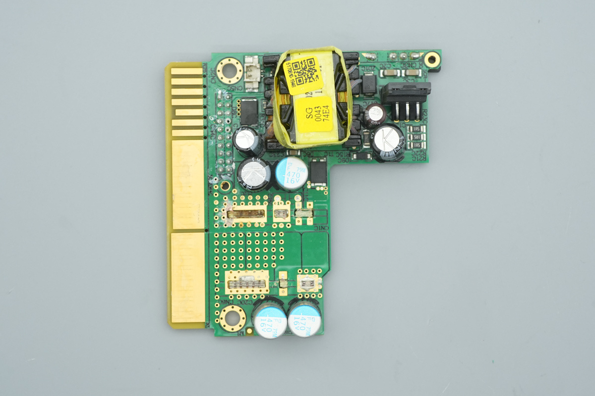
The gold-finger PCB features the standby power supply chip, standby power transformer, rectifier MOSFET, and filtering caps.
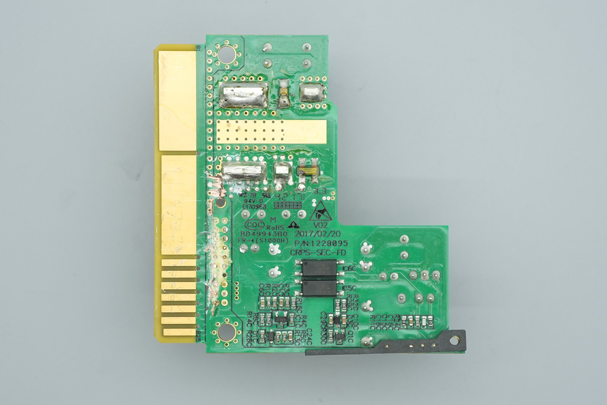
The feedback optocoupler is soldered onto the other side of the PCB.
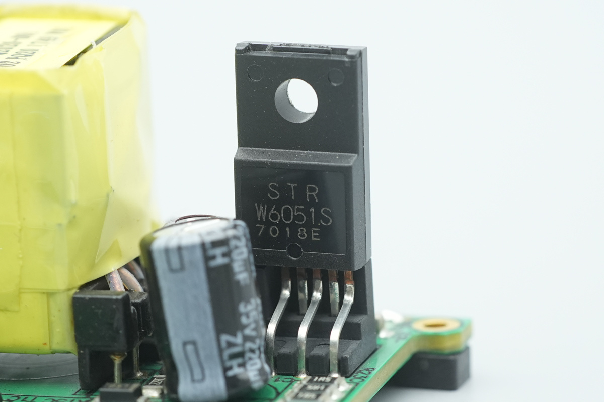
The standby power supply chip is from Sanken Electric, model STR-W6051S. It features an integrated 650V breakdown voltage switching MOSFET, an internal startup circuit and standby function, comprehensive protection features, and supports an output power of up to 30W. It is housed in a TO220F-6L package.
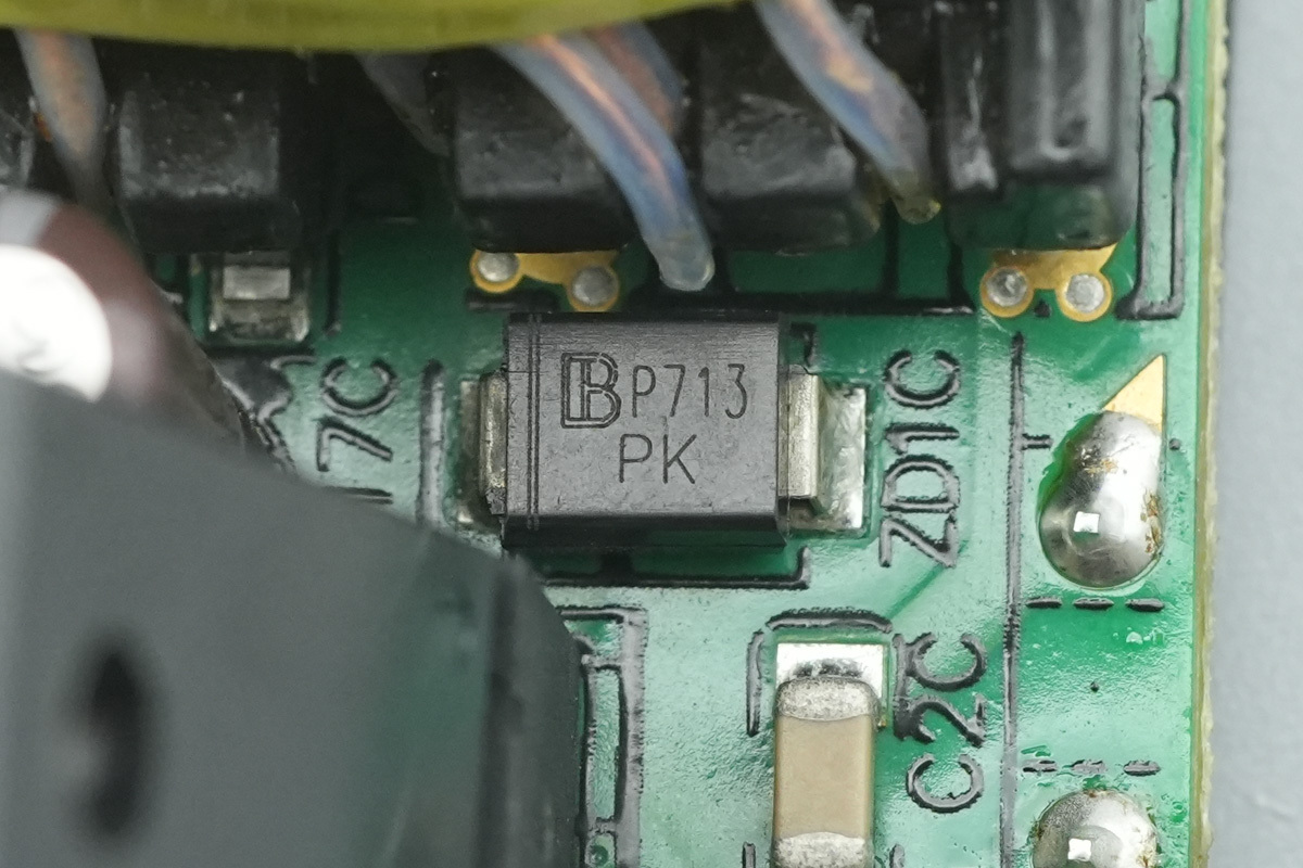
The TVS is from BrightKing, marked PK, model SMBJ130A, featuring a reverse standoff voltage of 130V and housed in an SMB package.
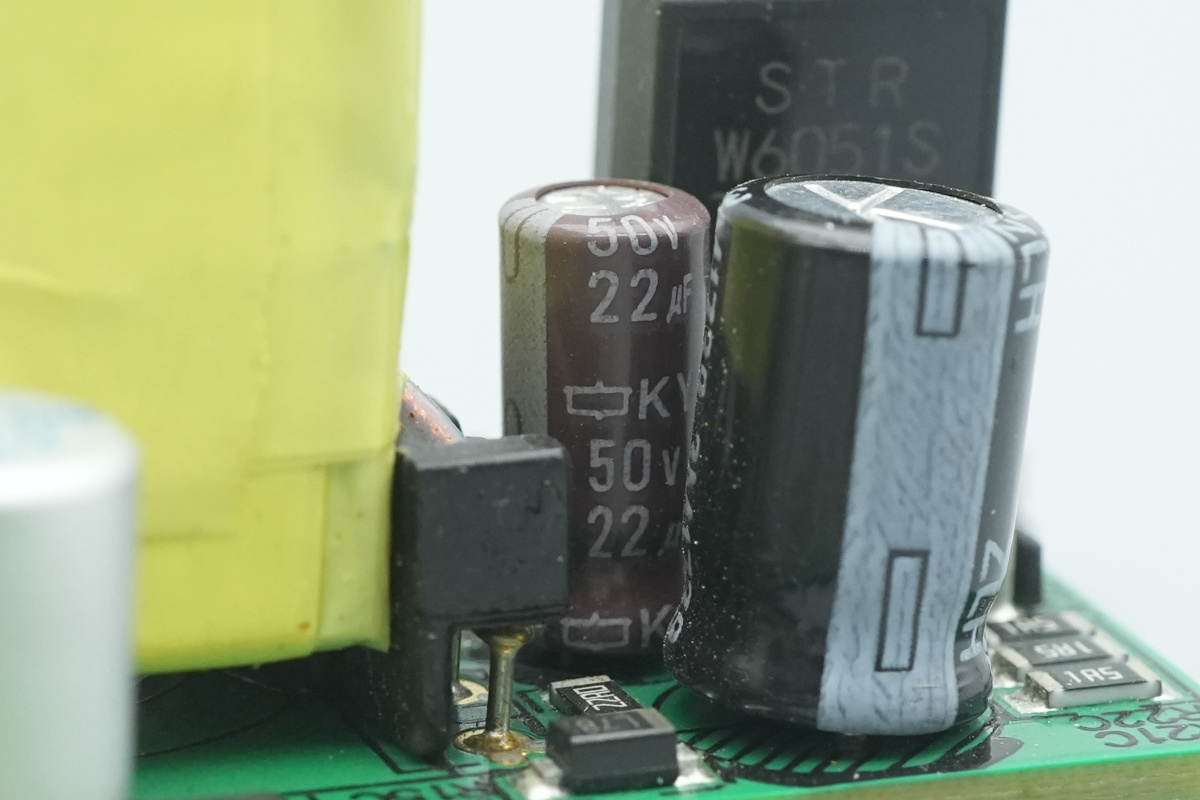
The filtering cap is from NCC, spec 50V 22μF.
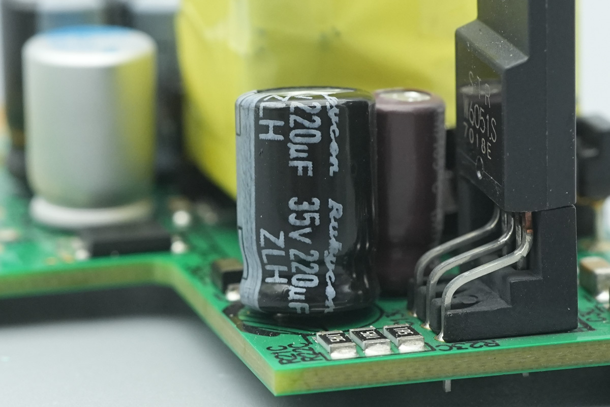
The filtering cap is from Rubycon, spec 35V 220μF.
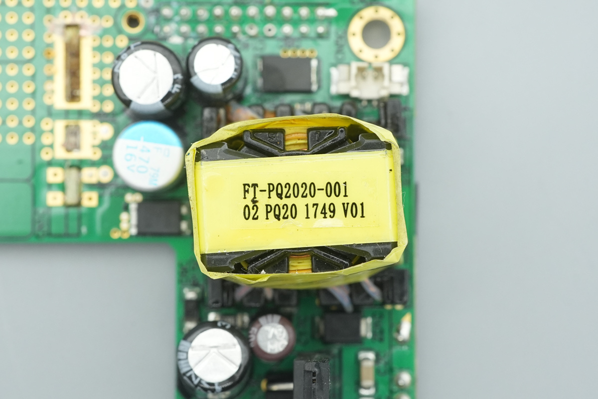
The transformer is tightly wrapped with adhesive tape for insulation.
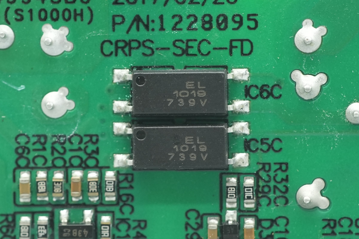
The Everlight EL1019 optocoupler is used for output voltage feedback.
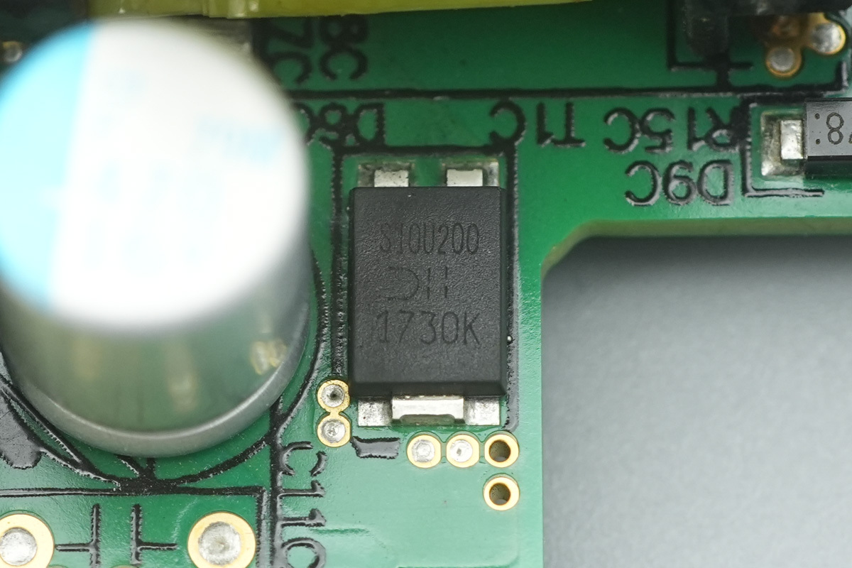
The diode is from DIODES, marked S10U200, model SBR10U200P5Q, spec 200V 10A, housed in a PowerDI5 package.
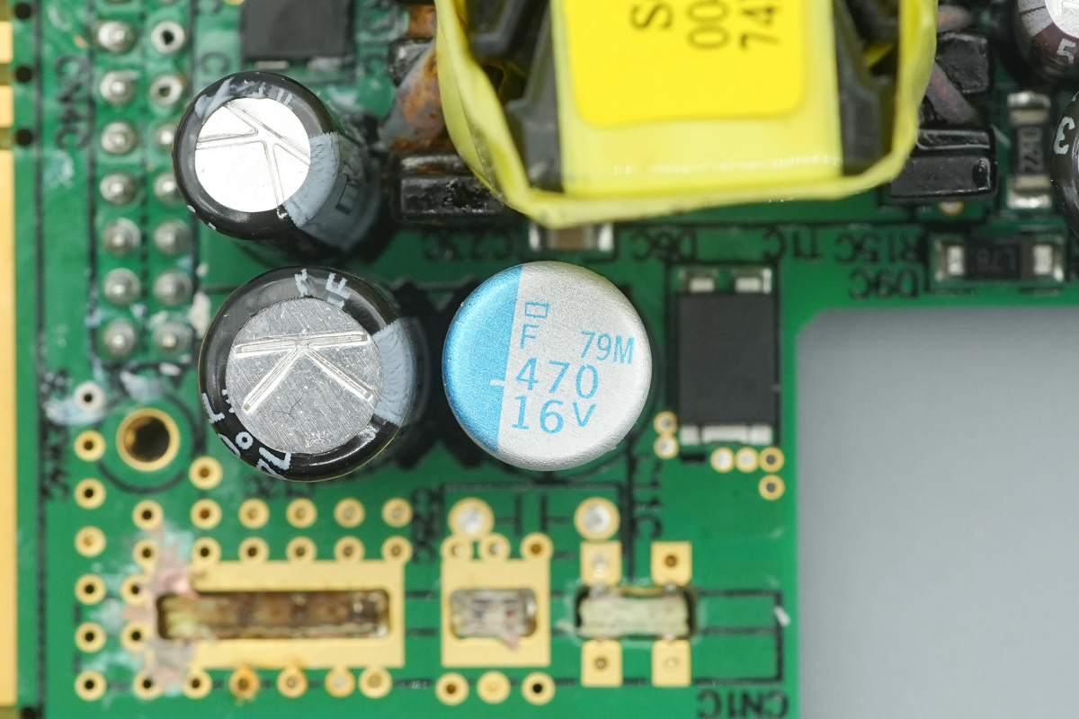
The filtering caps are from NCC, PSF series conductive polymer aluminum solid electrolytic caps, featuring ultra-low ESR, miniaturization, and long-life characteristics with a rated lifespan of 20,000 hours at 105°C, and spec 470μF 16V.
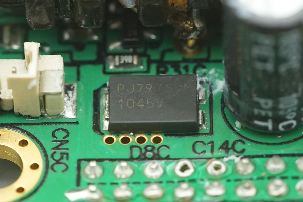
The diode is from PANJIT, marked 1045, model SVM1045V, rated at 45V 10A, housed in a TO-277 package.
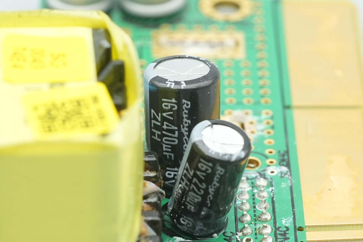
The filtering cap is from Rubycon, spec 16V 470μF.
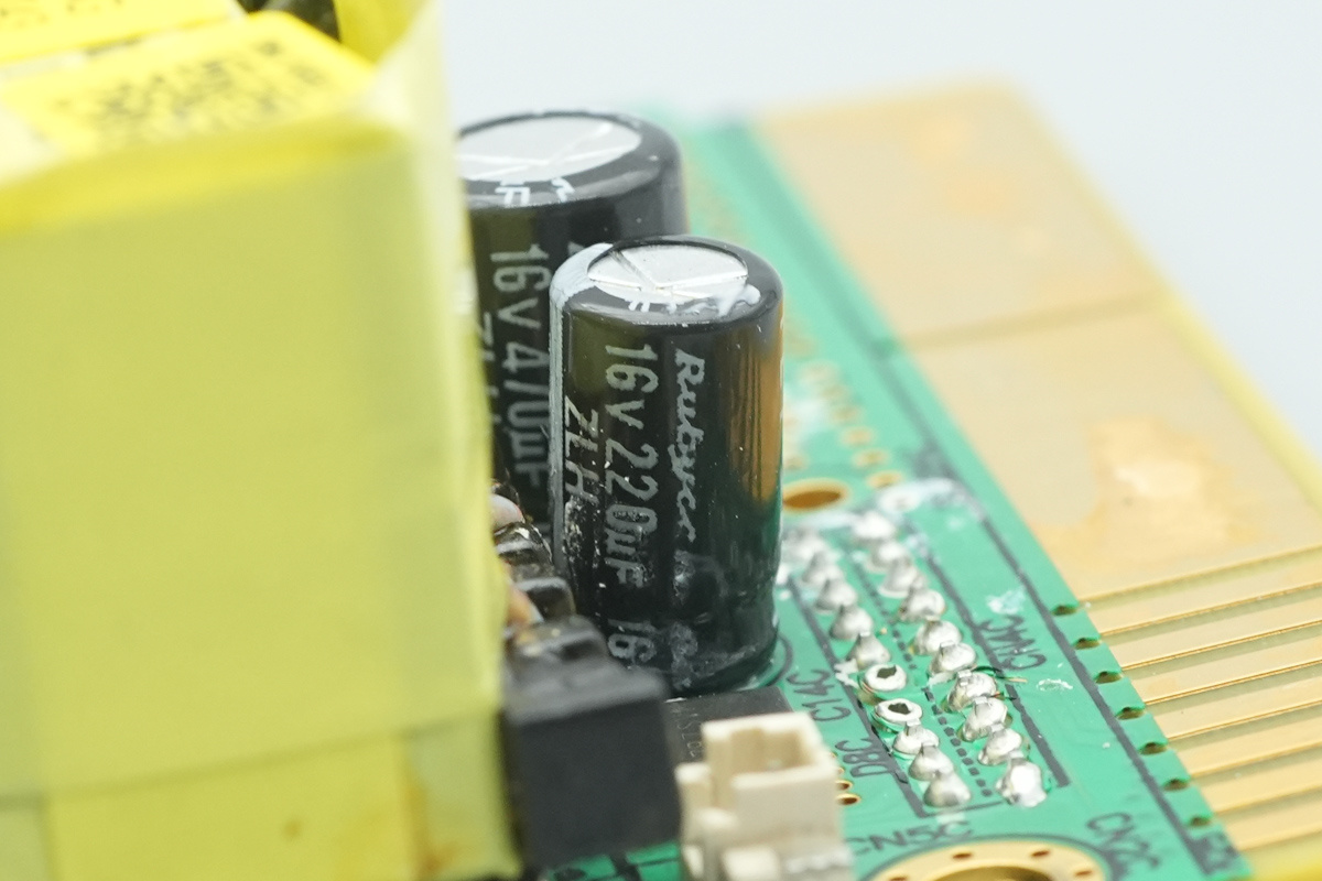
Another one, spec 16V and 220μF.
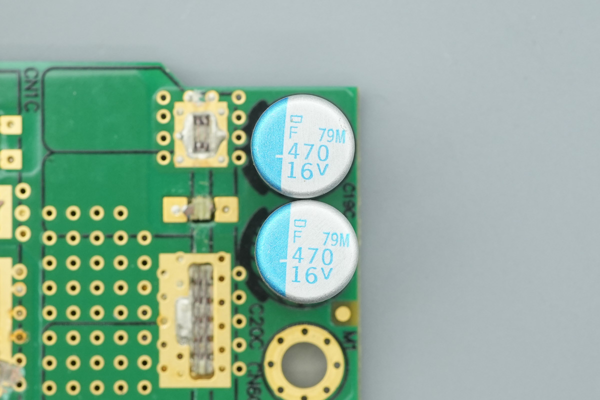
The filtering cap, spec 470μF 16V.
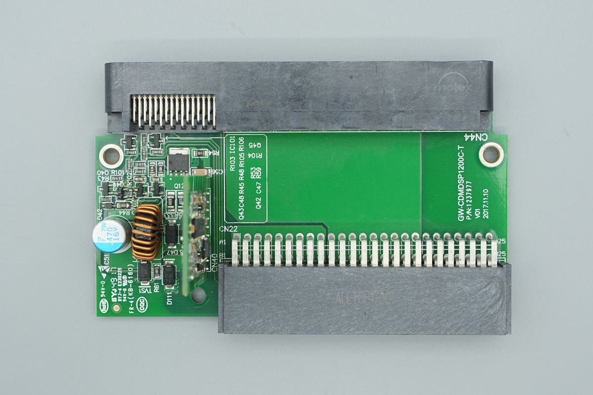
Connectors are soldered on both sides of the adapter PCB, with a vertical PCB, filtering caps, and a step-down choke soldered on the left.

There are no components on the back.
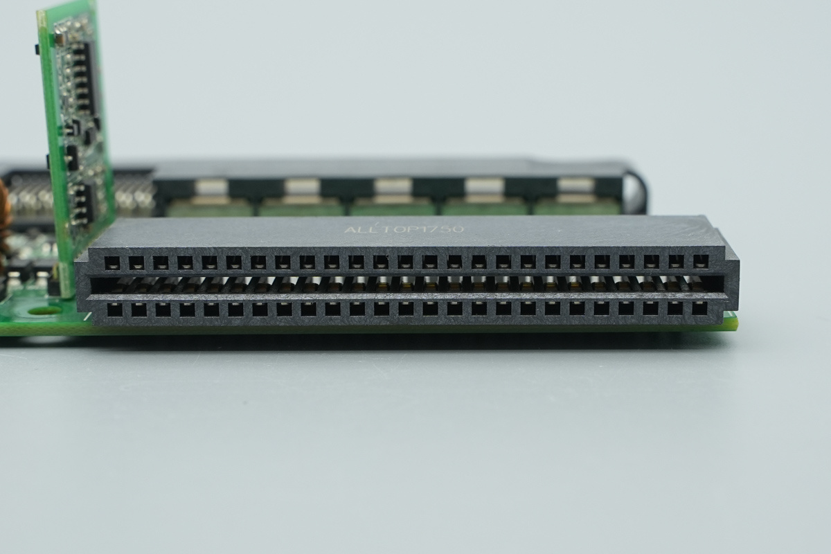
The connector on the PCB connects to the power module.
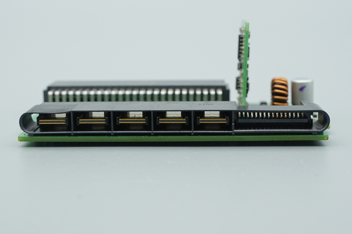
The PCB output connector.
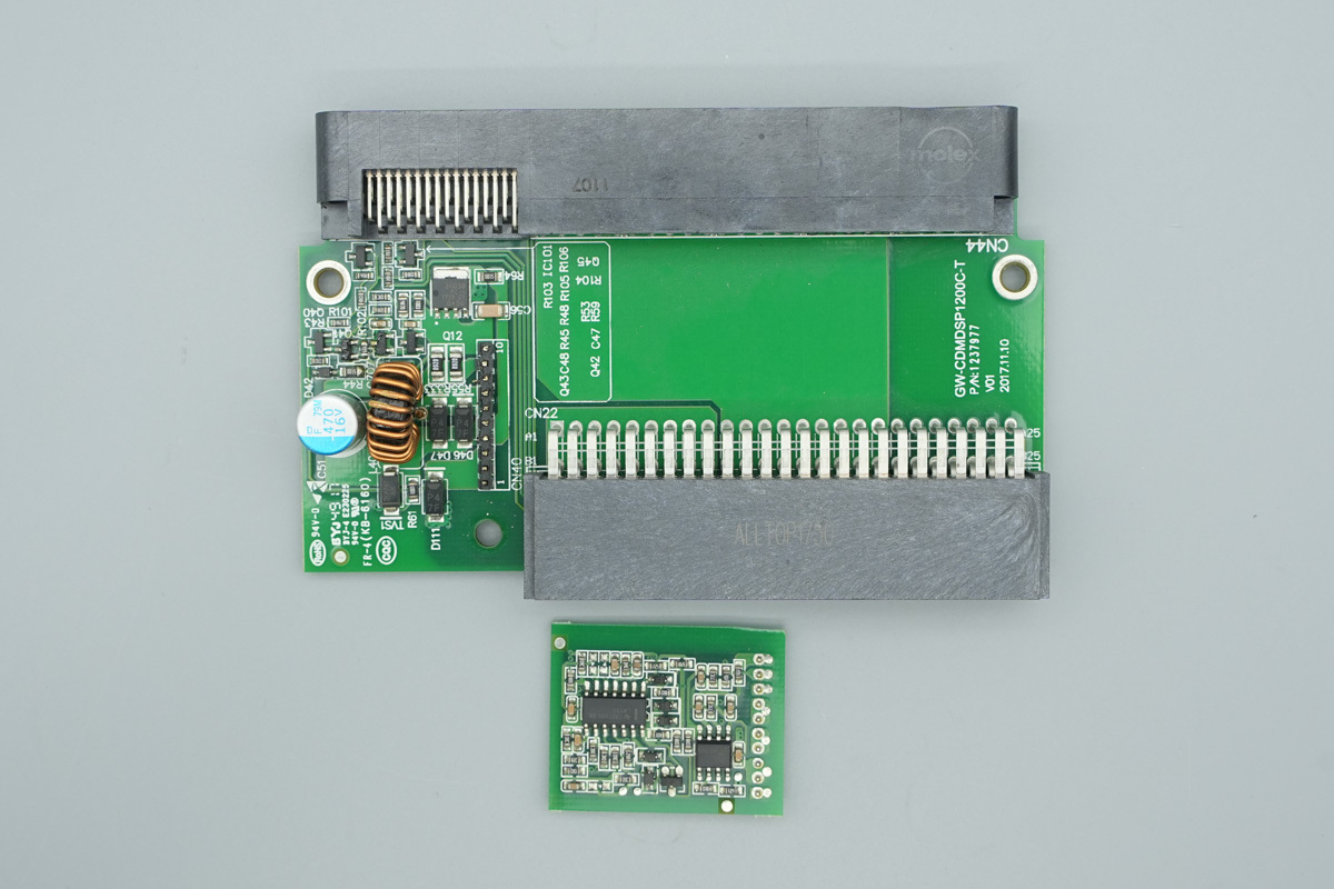
Remove the vertical PCB connected by pin headers.

One side of the vertical PCB features a synchronous buck controller and buck switching MOSFETs.
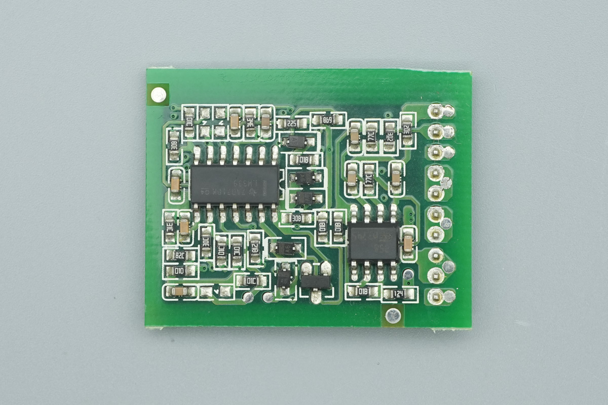
The other side is equipped with a voltage comparator and an operational amplifier.
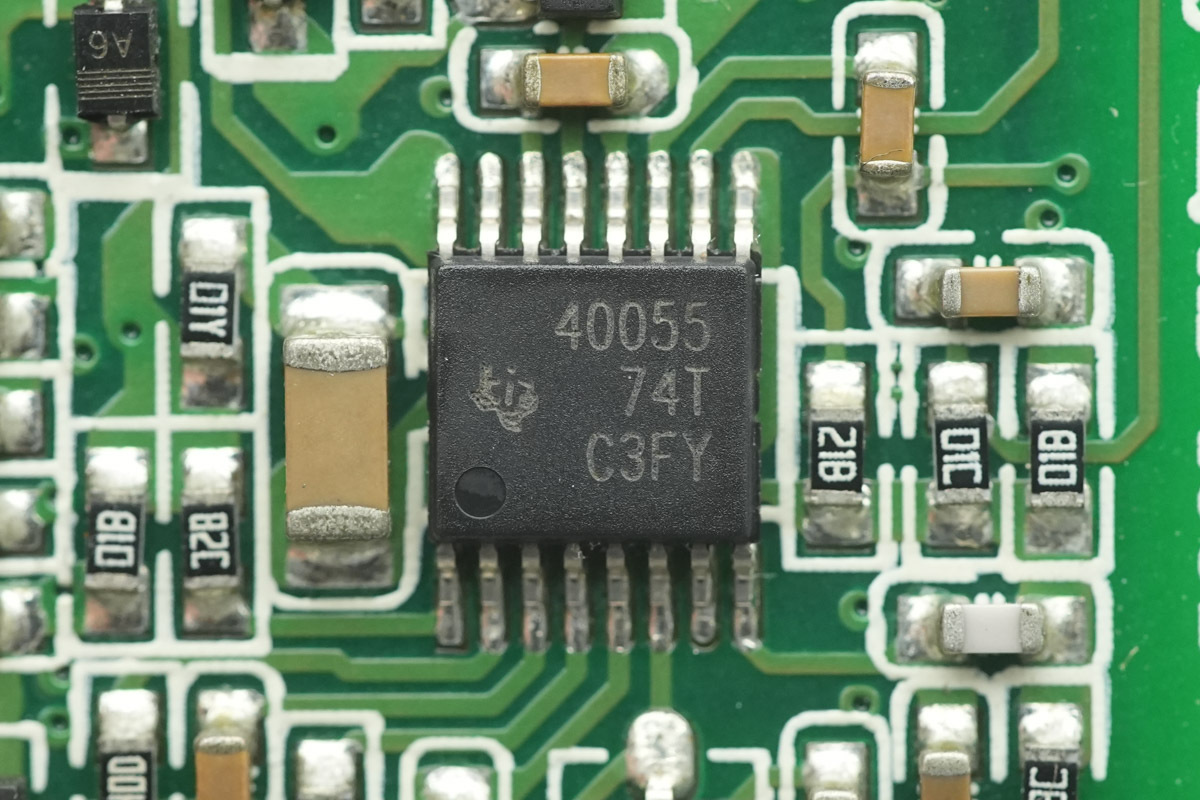
The synchronous buck controller is from TI, model TPS40055, a wide-input synchronous buck controller supporting an input voltage range of 8-40V, switching frequencies up to 1MHz, and featuring an integrated NMOS driver, OTP, and external synchronization, housed in an HTSSOP16 package.
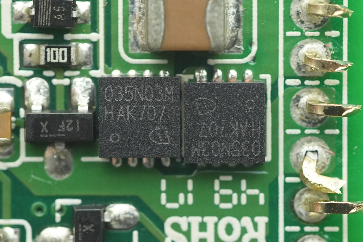
The synchronous buck switching MOSFETs are from Infineon, marked 035N03M, model BSZ035N03MS G, NMOS, 30V and 3.5mΩ, in a TSDSON-8 package.
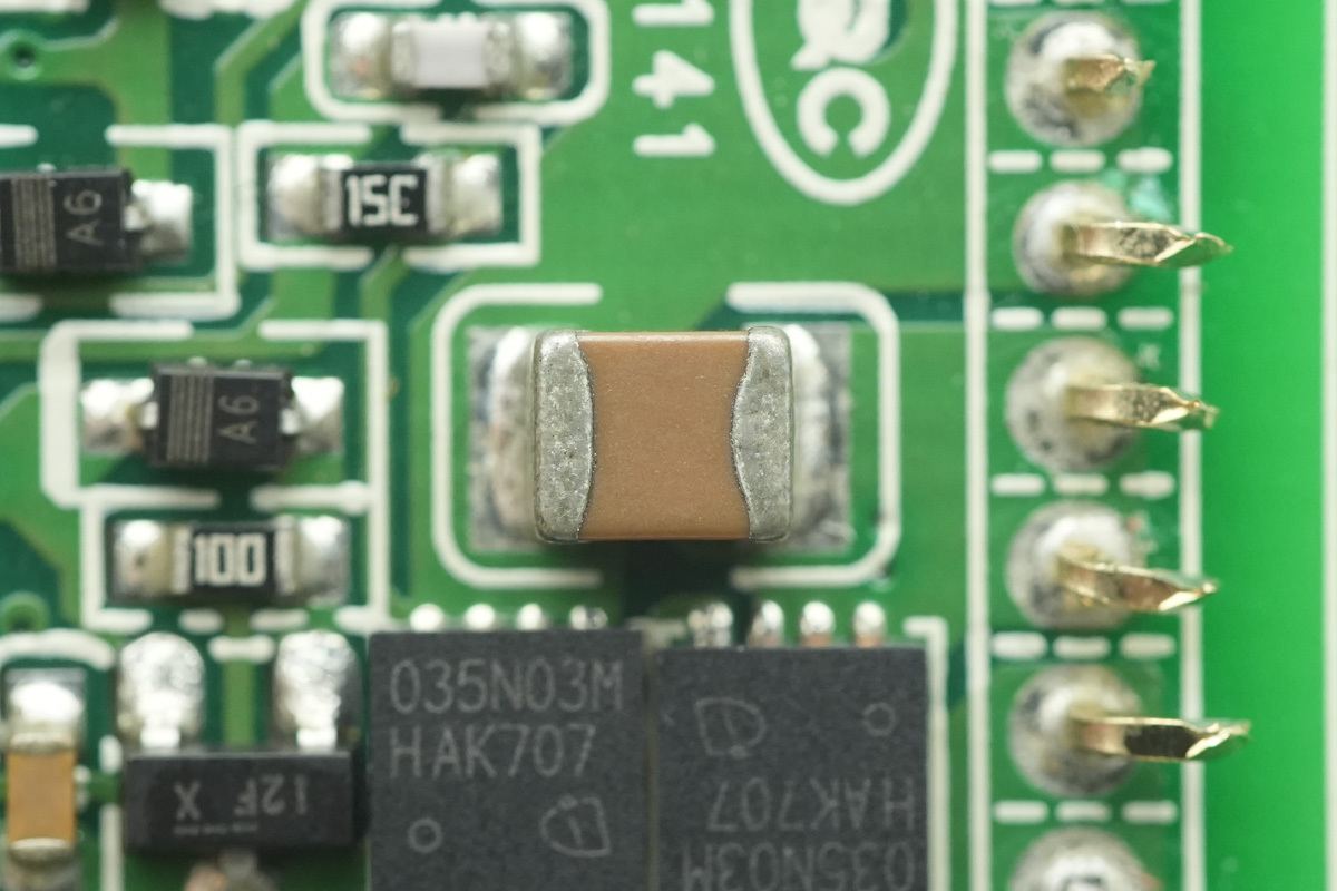
The MLCCs.
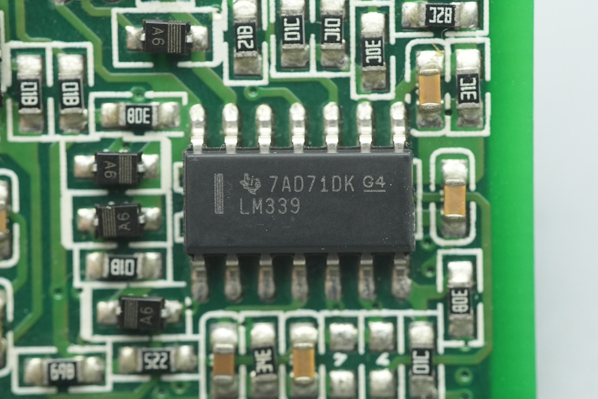
The voltage comparator is from TI, model LM339, a quad differential comparator housed in an SOIC14 package.
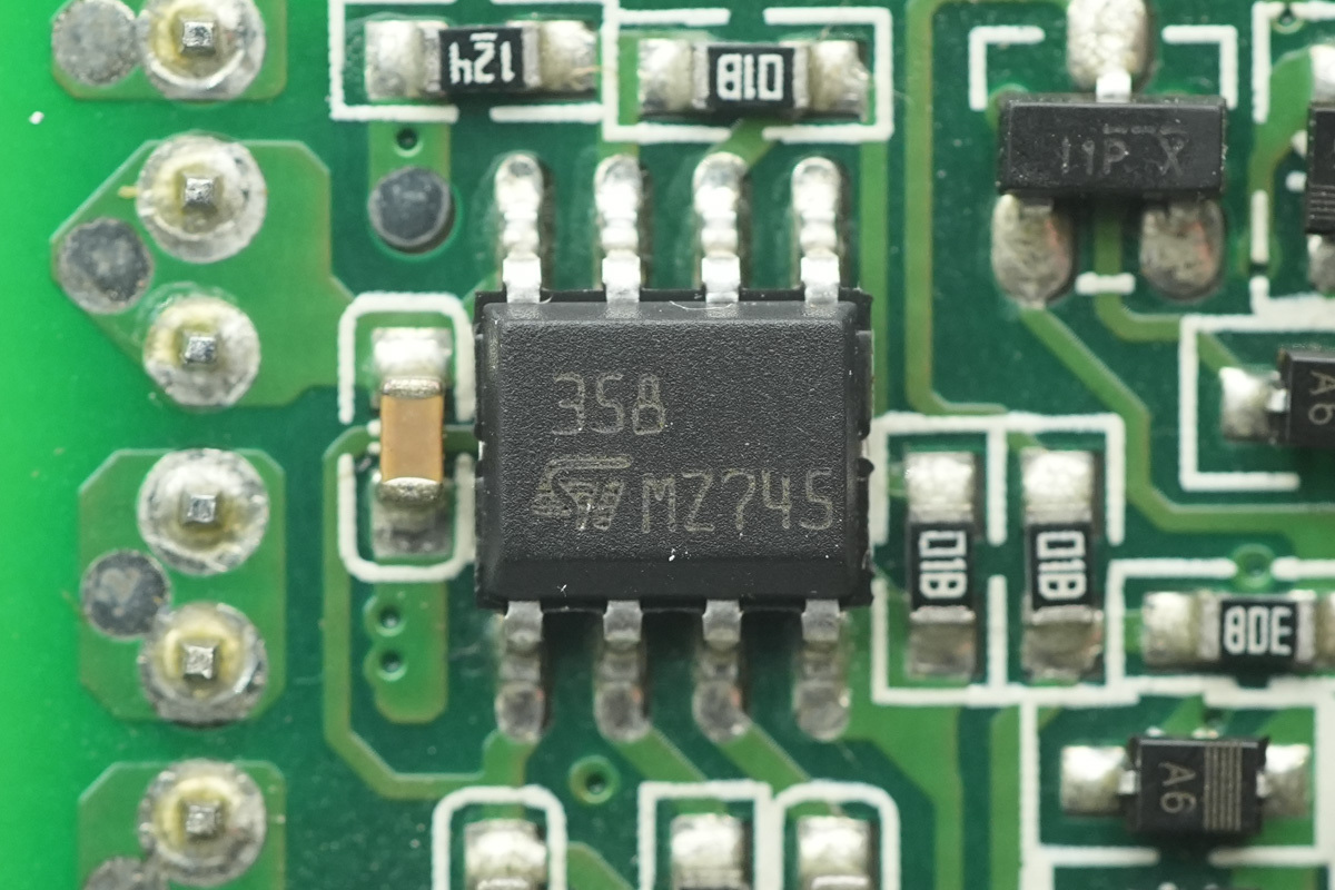
The operational amplifier is from ST, model LM358, a low-power dual operational amplifier in an SO8 package.
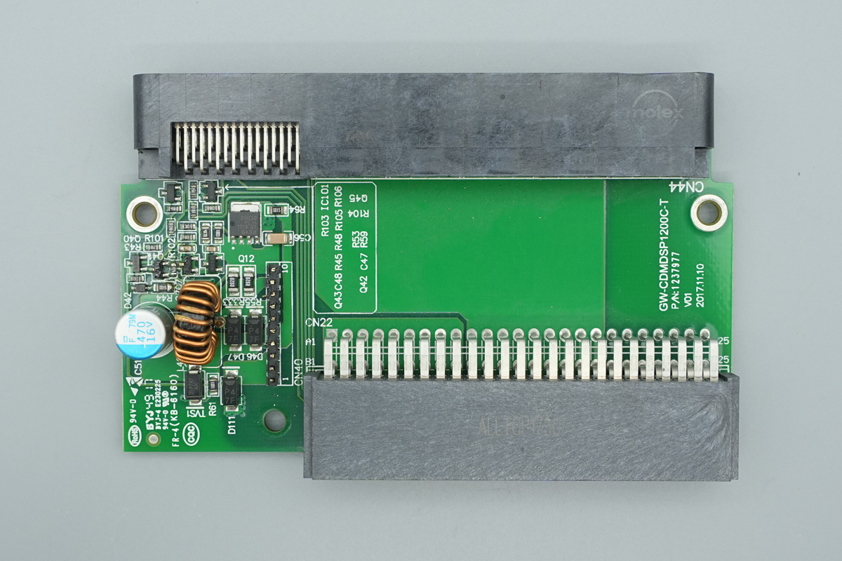
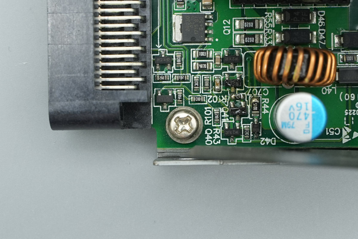
The PCB is equipped with a step-down choke, filtering caps, and a VBUS MOSFET.
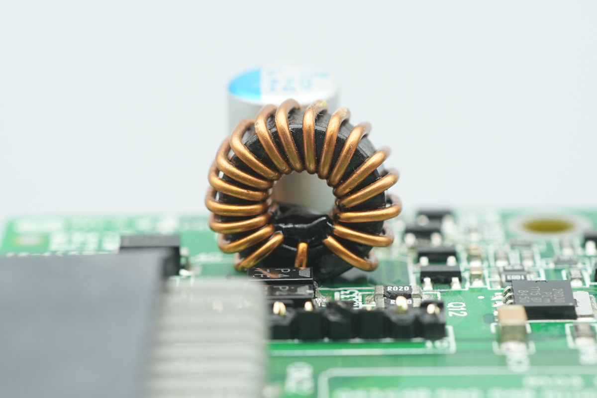
The step-down choke is wound with enameled wire.
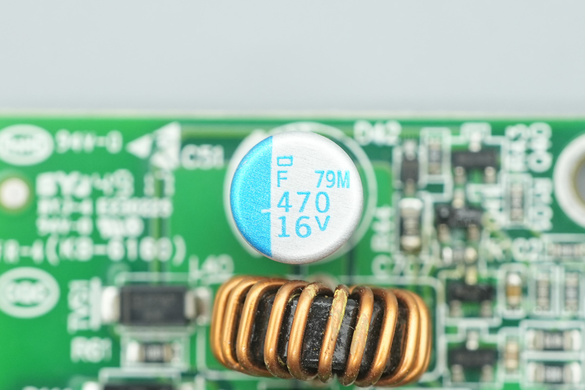
The filtering cap,spec 470μF 16V.
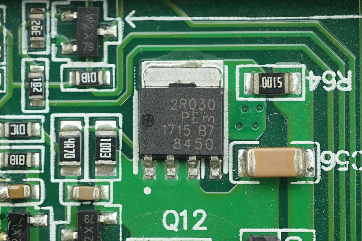
The output control MOSFET is from Nexperia, model PSMN2R0-30YL, NMOS, 30V and 2mΩ, housed in an LFPAK package.

Well, those are all components of the GreatWall 1200W SiC Server Power Supply GW-CDMDSP1200C.
Summary of ChargerLAB
The GreatWall 1200W SiC server power supply (GW-CDMDSP1200C) supports 100-240V AC and 240V HVDC inputs. It features a 12V/100A main output and a 5V/6A standby output, equipped with a cooling fan, an IEC inlet, and rear output connectors.
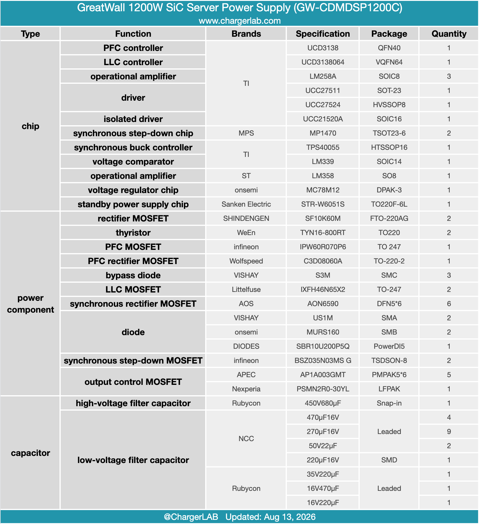
The teardown reveals a rich component lineup centered around TI controllers: the PFC stage uses a UCD3138 controller, an Infineon IPW60R070P6 MOSFET with a TI UCC27511 driver, and a Wolfspeed C3D08060A SiC diode. The LLC stage employs a UCD3138064 controller, a TI UCC21520A isolated driver, and Littelfuse IXFH46N65X2 MOSFETs.
For synchronous rectification, it uses AOS AON6590 MOSFETs with a TI UCC27524 driver. The standby circuit relies on a Sanken Electric STR-W6051S IC, while the adapter PCB integrates a TI TPS40055 buck controller and an Infineon BSZ035N03MS G MOSFET. Built with solid Japanese caps throughout, extensive glue reinforcement, and conformal coating, the unit showcases professional-grade manufacturing.