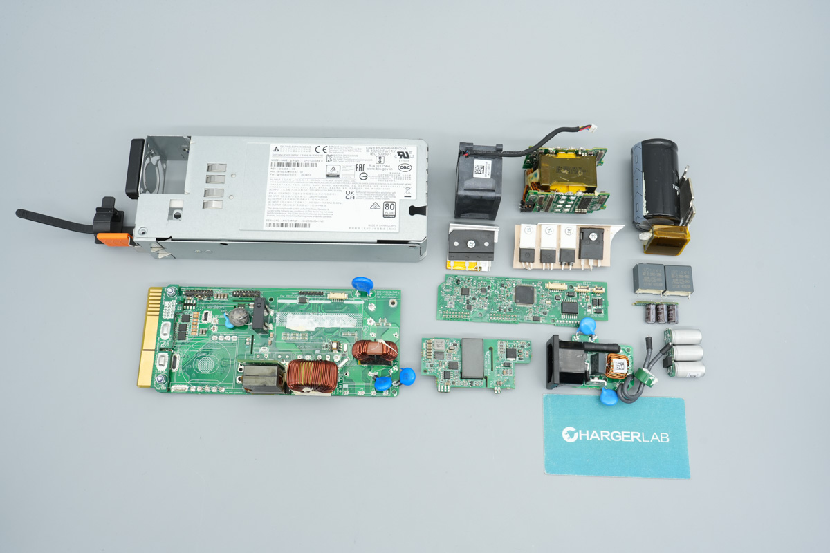

Introduction
In this teardown, we are taking apart the Delta 1100W SiC power supply module. Sporting the model DPS-1100AB-11 A, this unit supports a wide 115-240V AC input, delivers a -56V output at 19.64A, and maxes out at a hefty 1100W of total output power. The exterior packs a standard power receptacle and LED indicators, while the back end houses a cooling fan and heavy-duty connectors.
Built with a sleek, elongated chassis tailored for Cisco switch deployment, this powerhouse relies on an advanced interleaved PFC plus phase-shifted full-bridge architecture, featuring high-efficiencySiC diodes for PFC rectification. Join us at ChargerLAB as we dive into the teardown and explore the high-end engineering and components packed inside.
Product Appearance
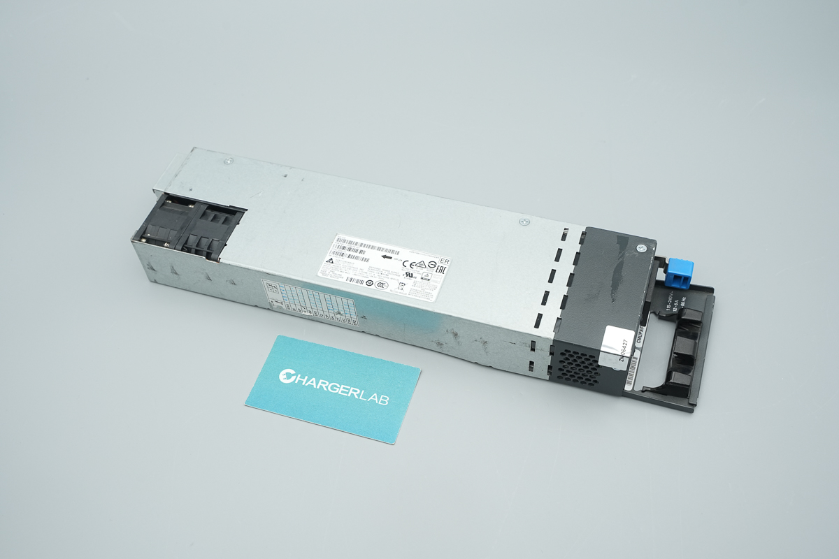
This Delta SiC power supply features a galvanized steel sheet casing, with a label affixed to the front of the unit.
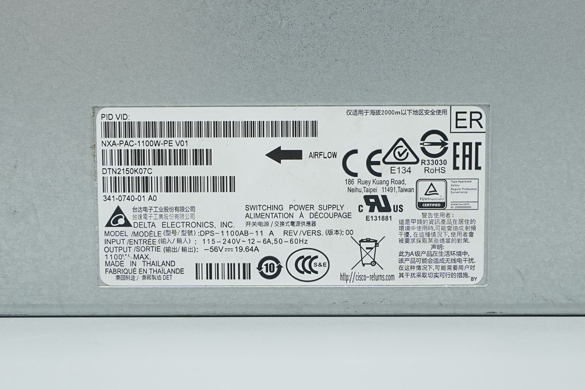
The power supply spec label:
Model: DPS-1100AB-11 A
Input: 115-240V~ 12-6A, 50-60Hz
Output: -56V ⎓ 19.64A, 1100W MAX
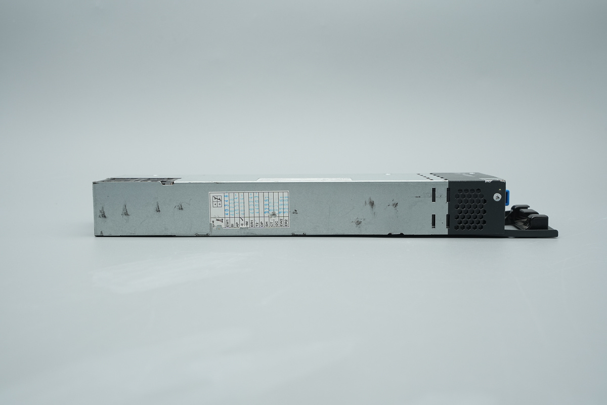
A label is affixed to the side of the casing.
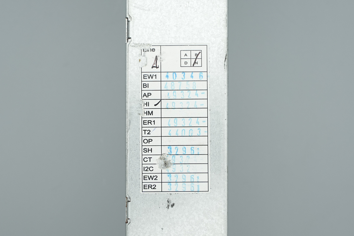
The label affixed to the side.
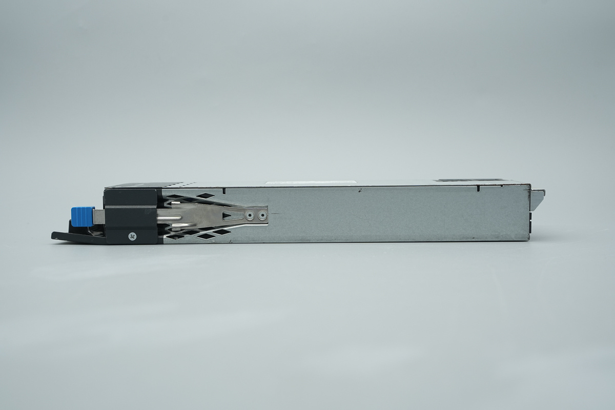
A release latch is provided on the side of the casing.
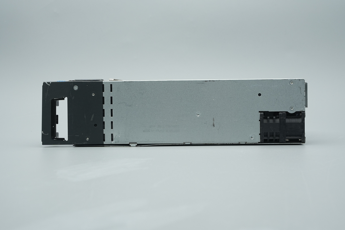
The rear section features a hollowed-out ventilation grille housing a cooling fan.
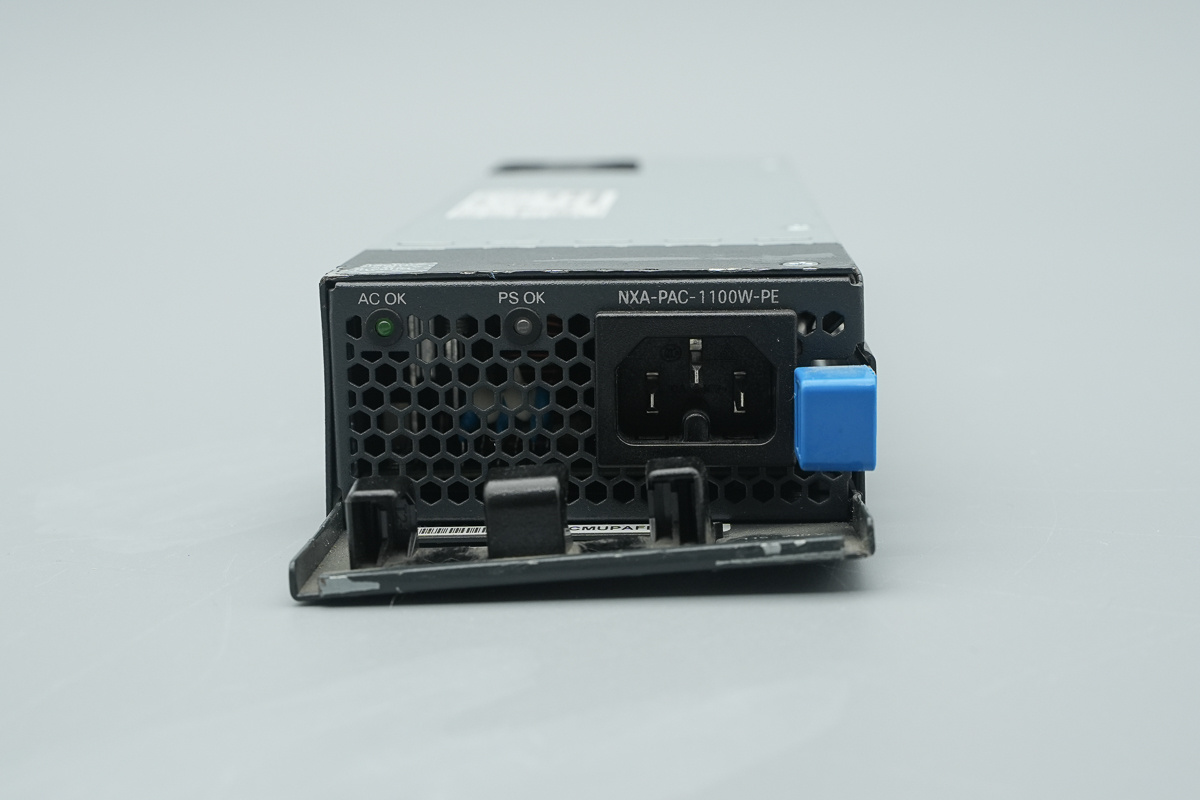
The input end is equipped with a handle, the LED indicators, cooling holes, an IEC C14power socket, and a release handle.
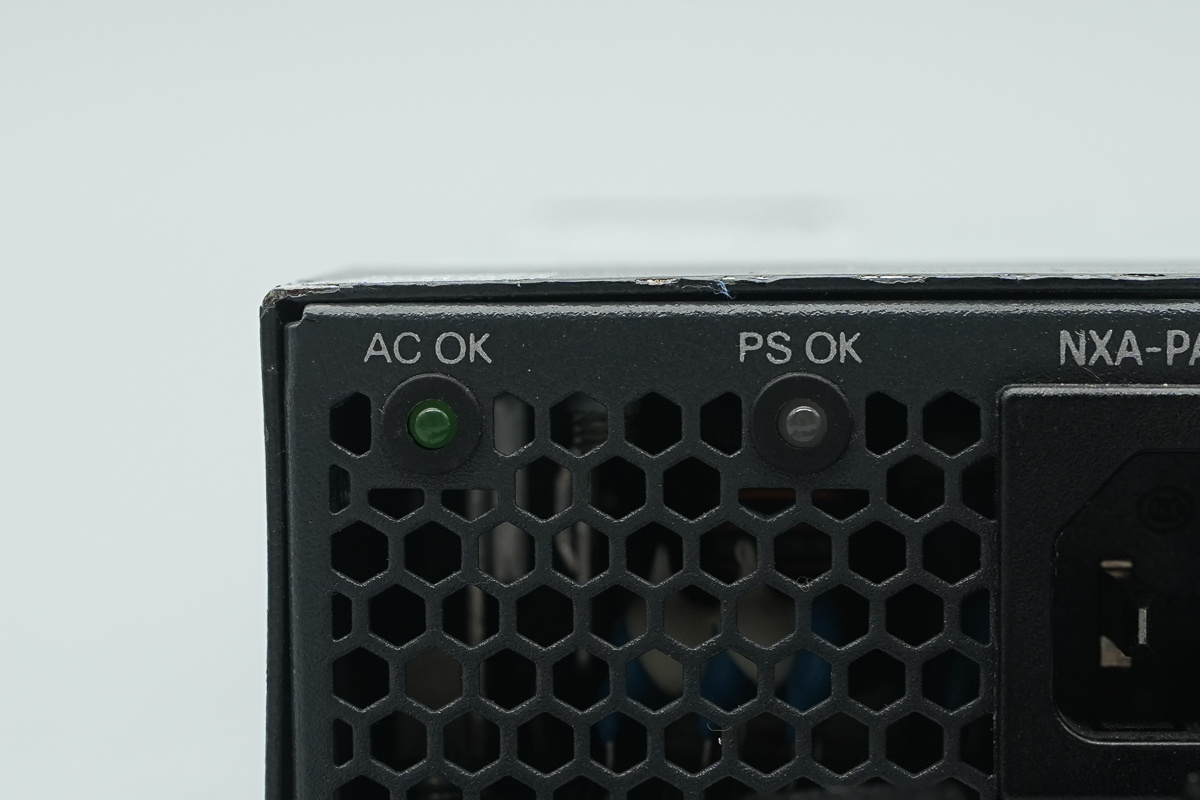
Here are the LED indicators.
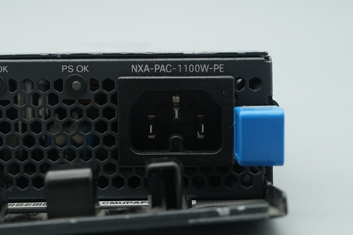
The IEC C14 power socket.
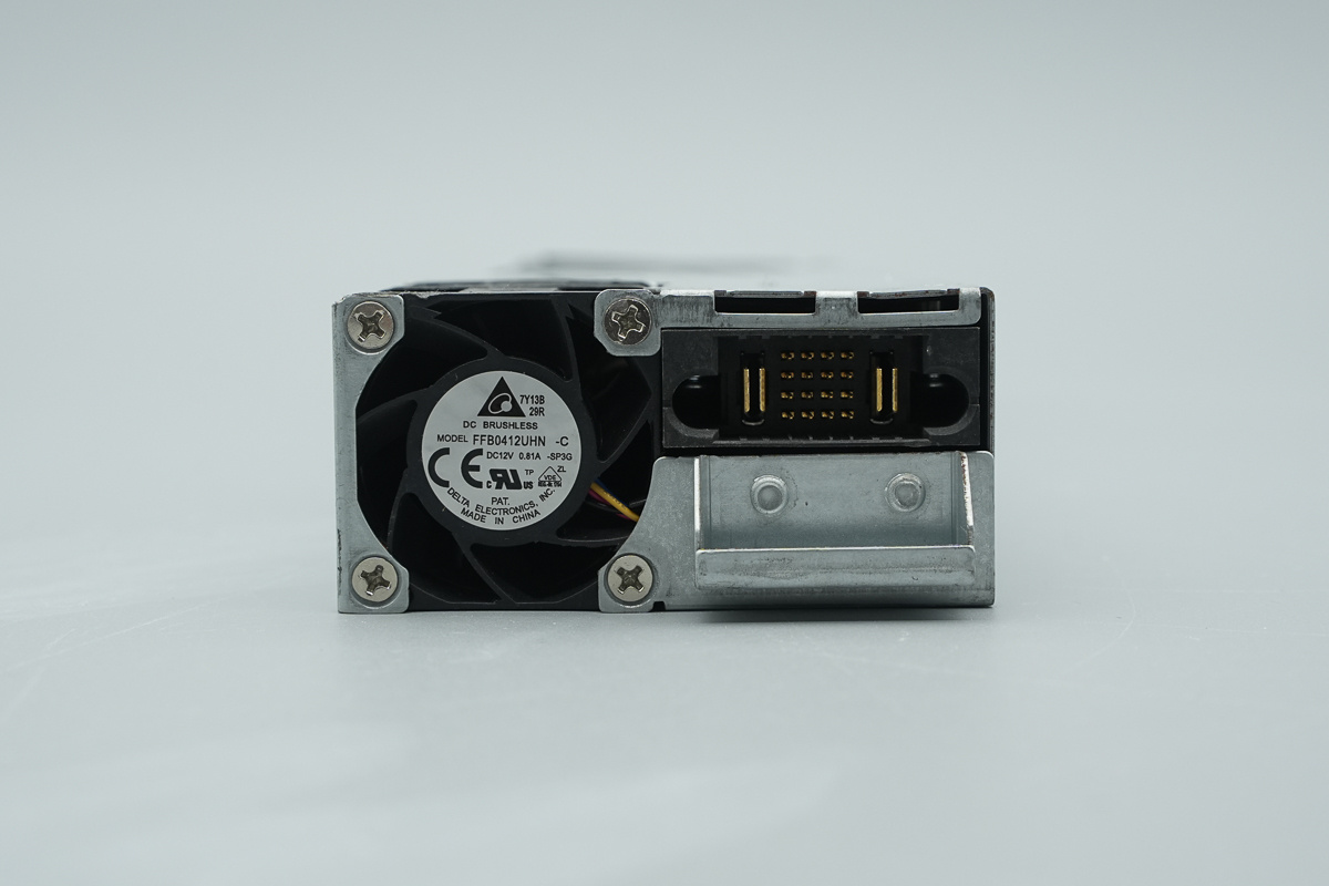
The output end is equipped with a cooling fan and a connector.
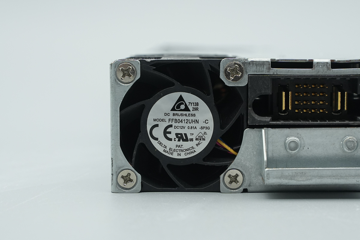
The cooling fan is from Delta, model FFB0412UHN, spec 12V 0.81A, featuring stationary guide vanes, made in China.
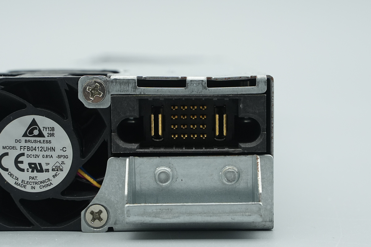
The gold-plated output connector.

The length of the power supply is about 362mm (14.252 inches).
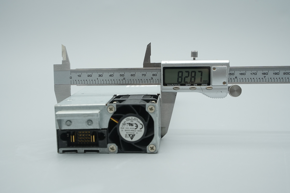
The width of the power supply is about 82.9mm (3.264 inches).
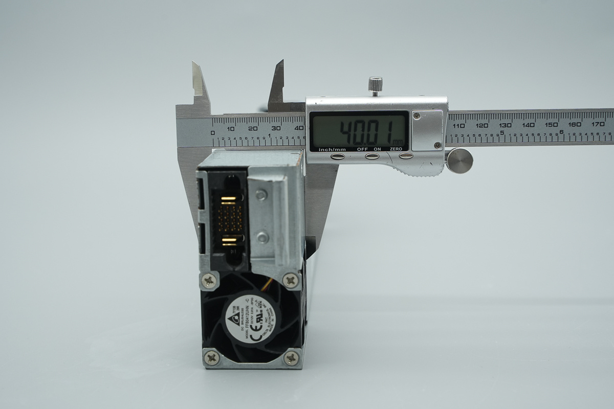
The thickness of the power supply is about 40mm (1.575 inches).
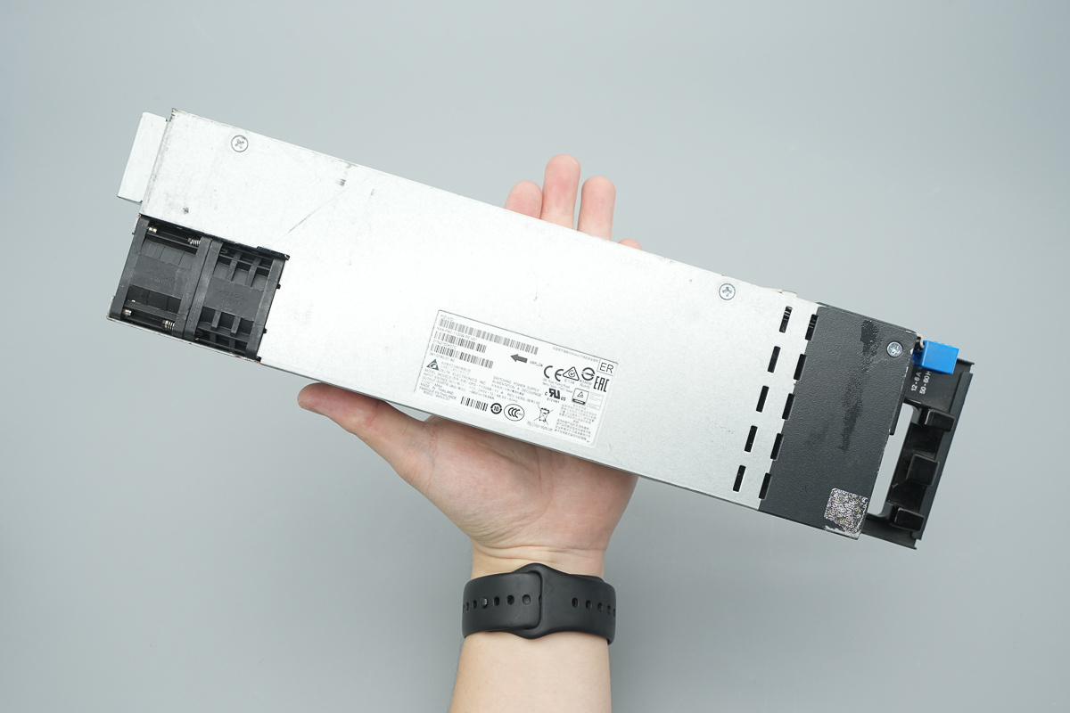
That's how big it is in the hand.
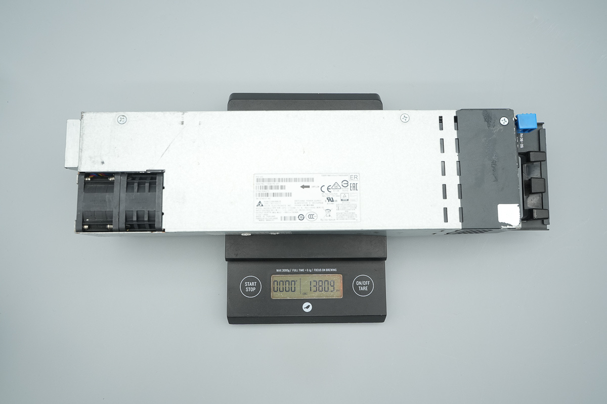
The weight is about 1381g (48.713 oz).
Teardown
Now that we've checked out the exterior of the Delta server power supply, it is time to crack it open and explore the high-end engineering and components inside.
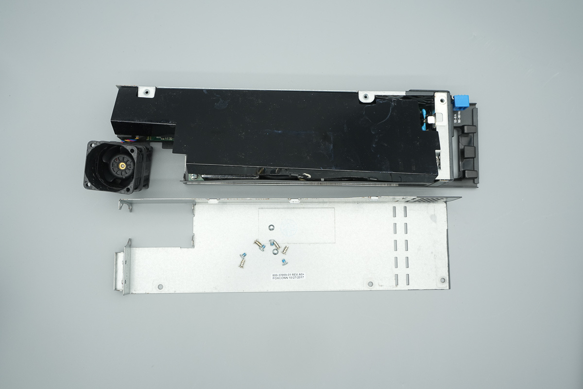
First, unscrew the fixing screws and open the casing. The PCBA module is covered with Mylar insulation sheet.
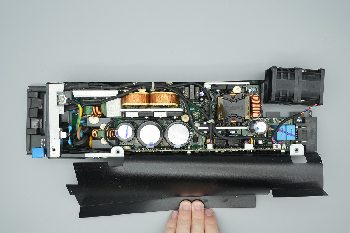
The Mylar sheet houses the PCBA module inside.
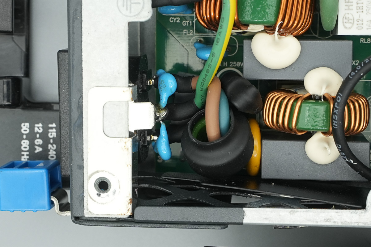
The power AC input wire is connected via soldering.
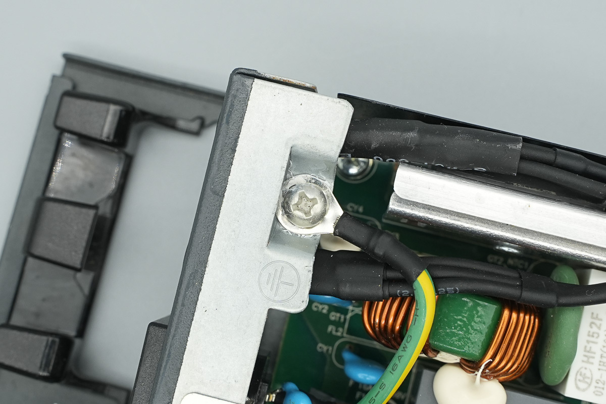
The grounding wire is secured to the casing using a screw.
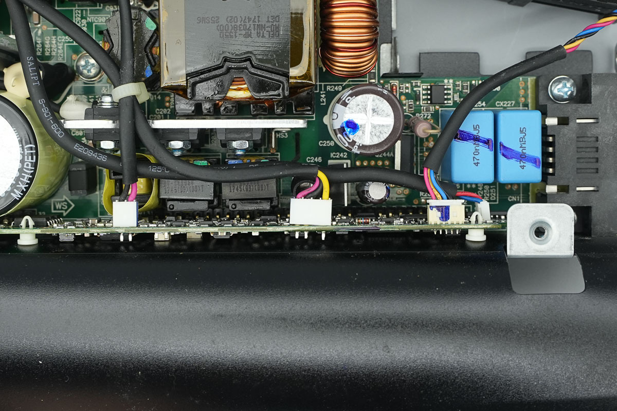
The LED indicator is connected via soldering, and the cooling fan is connected via a plug-in connector.
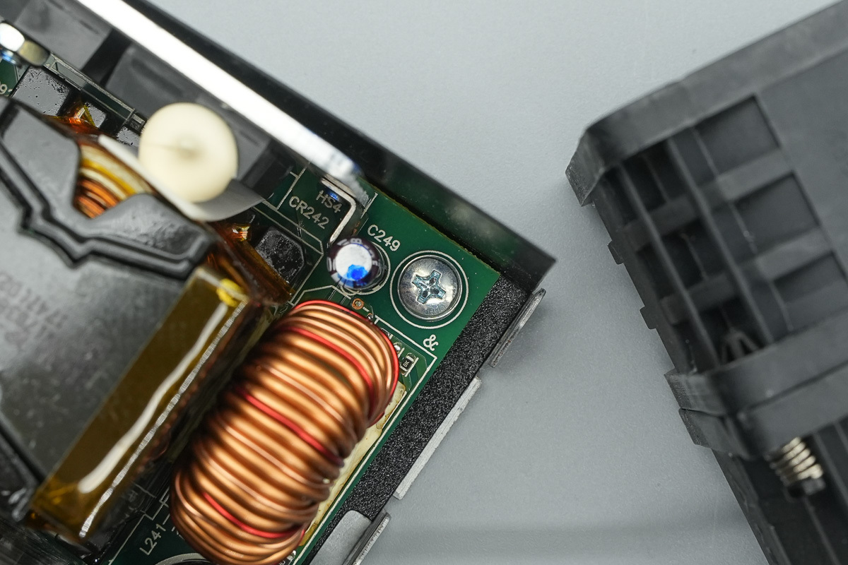
The PCBA module is secured using screws.
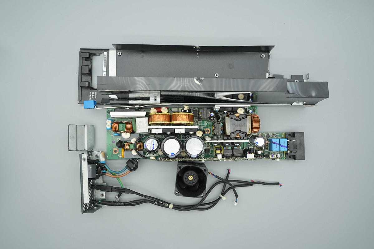
Unscrew the fixing screws and extract the PCBA module from the casing.
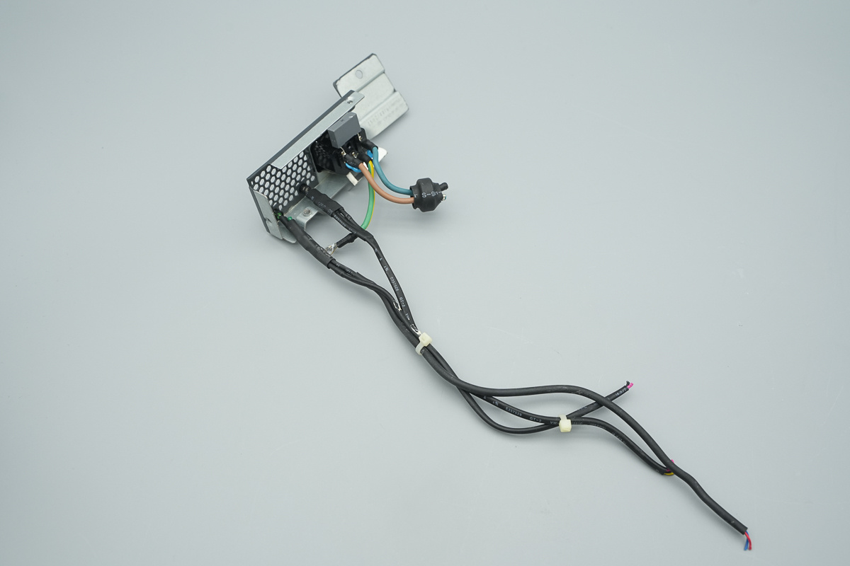
The power socket is secured to the casing.
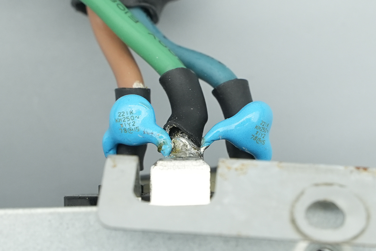
The two blue Y-caps come from muRata, model 221K.
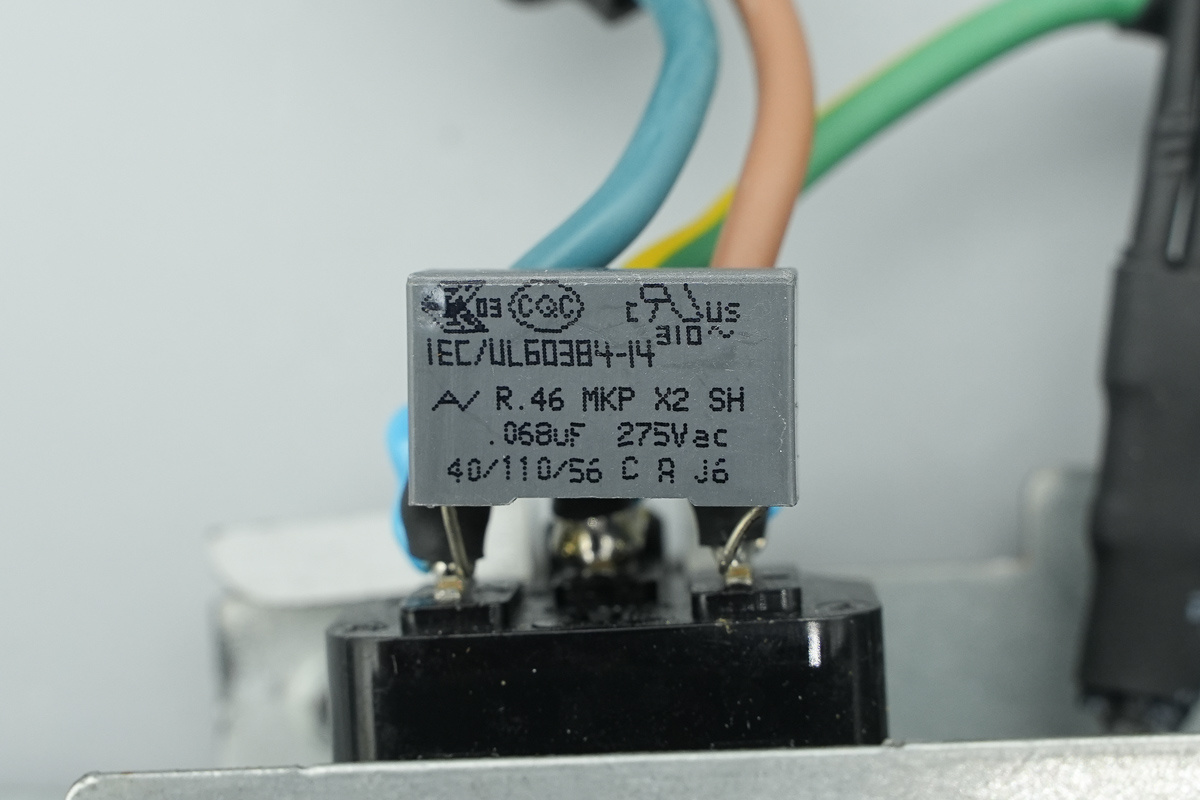
The safety X2 cap, spec 0.068μF.
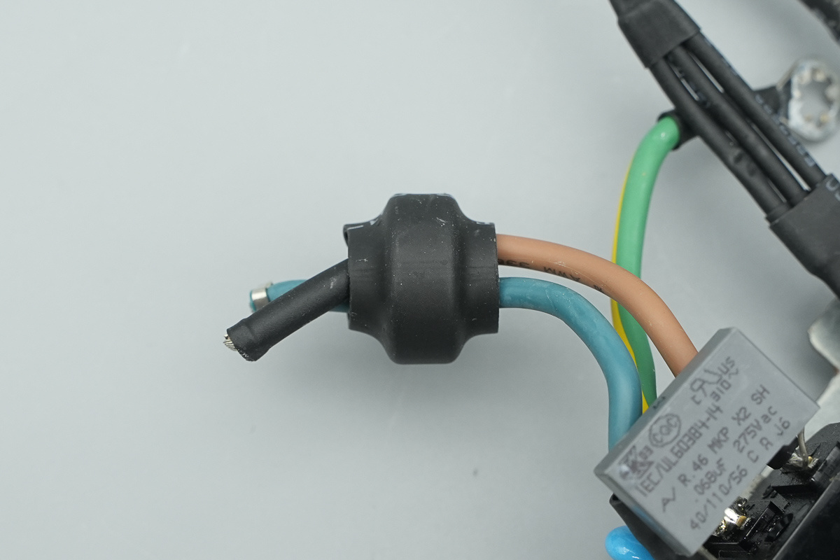
The magnetic ring used for suppressing high-frequency interference.
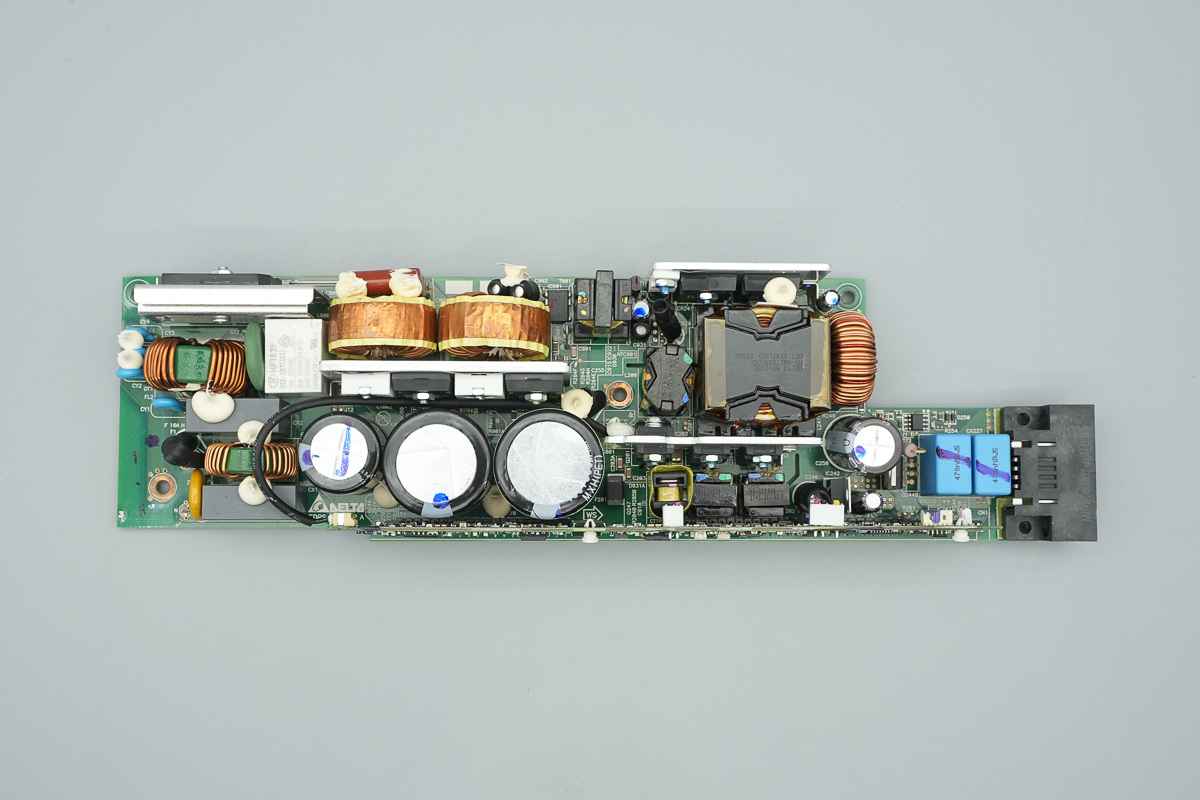
This is the frontof the PCBA module, the left is equipped with a fuse, a varistor, an X2 safety cap, a common-mode choke, a rectifier bridge, a relay, and an NTC thermistor. The middle section features the PFC boost choke, PFC MOSFETs, PFC rectifier MOSFETs, and high-voltage filter caps. The right is fitted with rectifierMOSFETs, a transformer, phase-shifted full-bridge MOSFETs, a drive transformer, and a control PCB. Film caps and connectors are also located on the right.
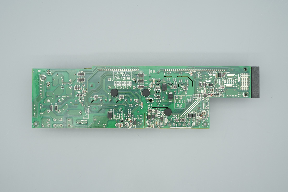
The back features current sense resistors, with a slot-isolation milled between the primary and secondary sides.
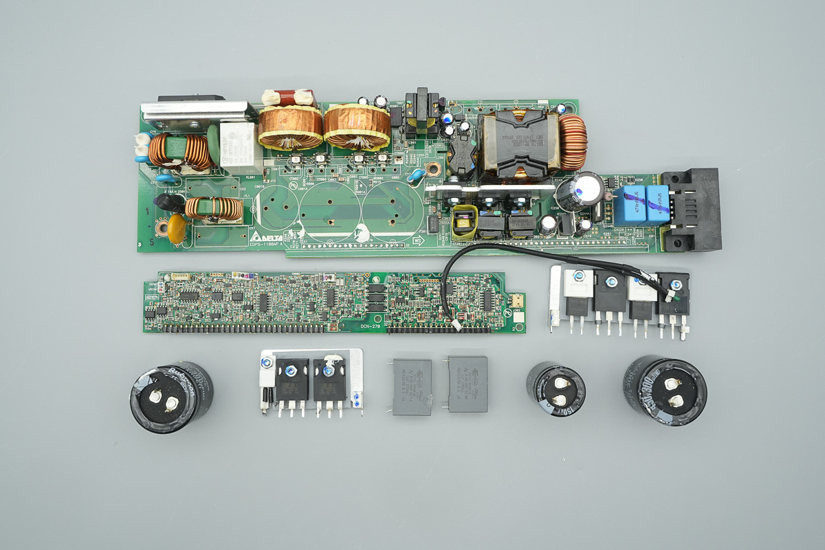
The heatsinks, high-voltage filter caps, and control PCB are desoldered and removed to continue the teardown.
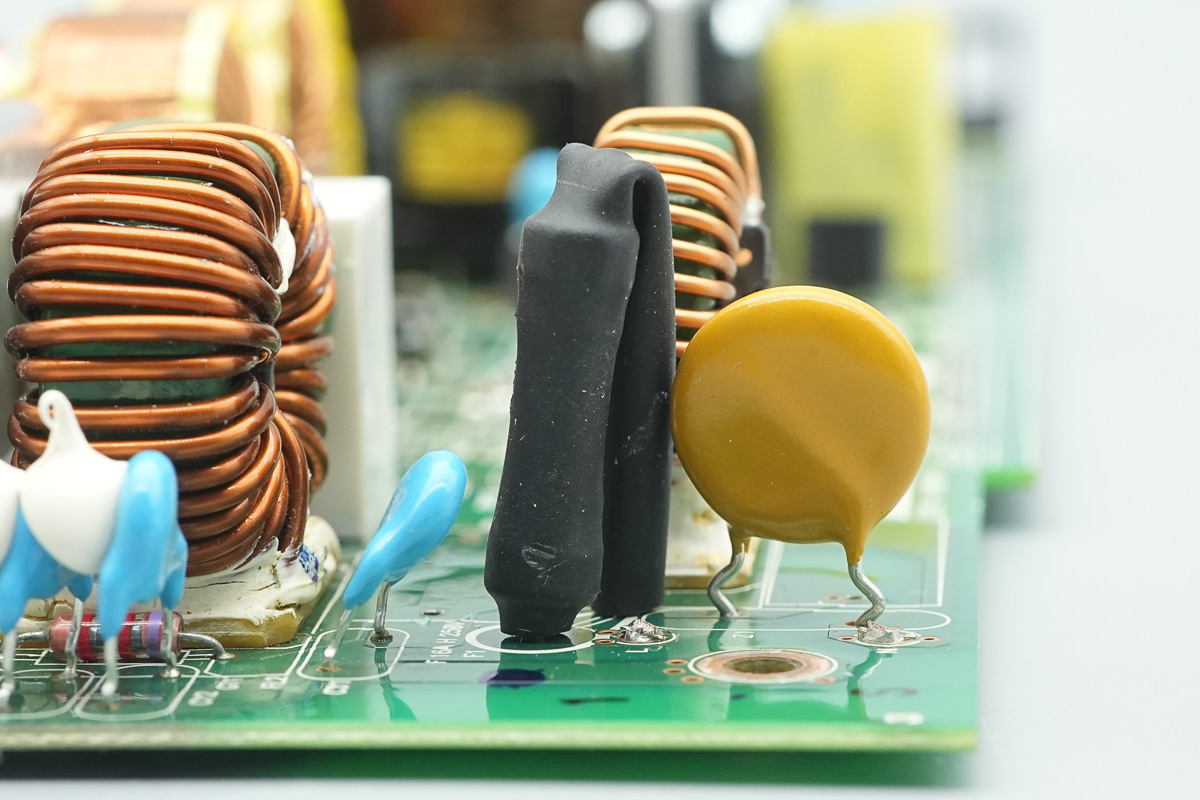
The input fuse is jacketed with a heat-shrink tubing for insulation, rated at 16A 250V.
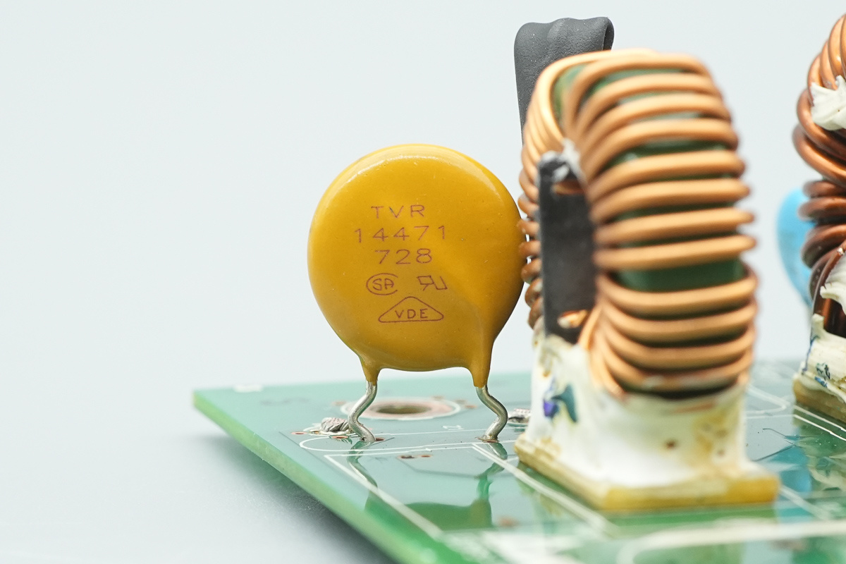
The varistor, model TVR14471, is used to absorb overvoltage surges.
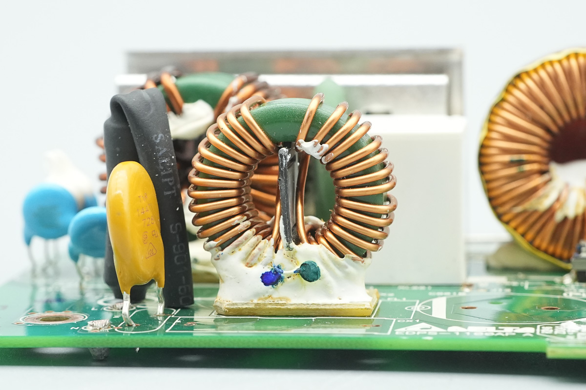
The common-mode choke is wound with enameled wire, with Bakelite board insulation provided inside and at the bottom.
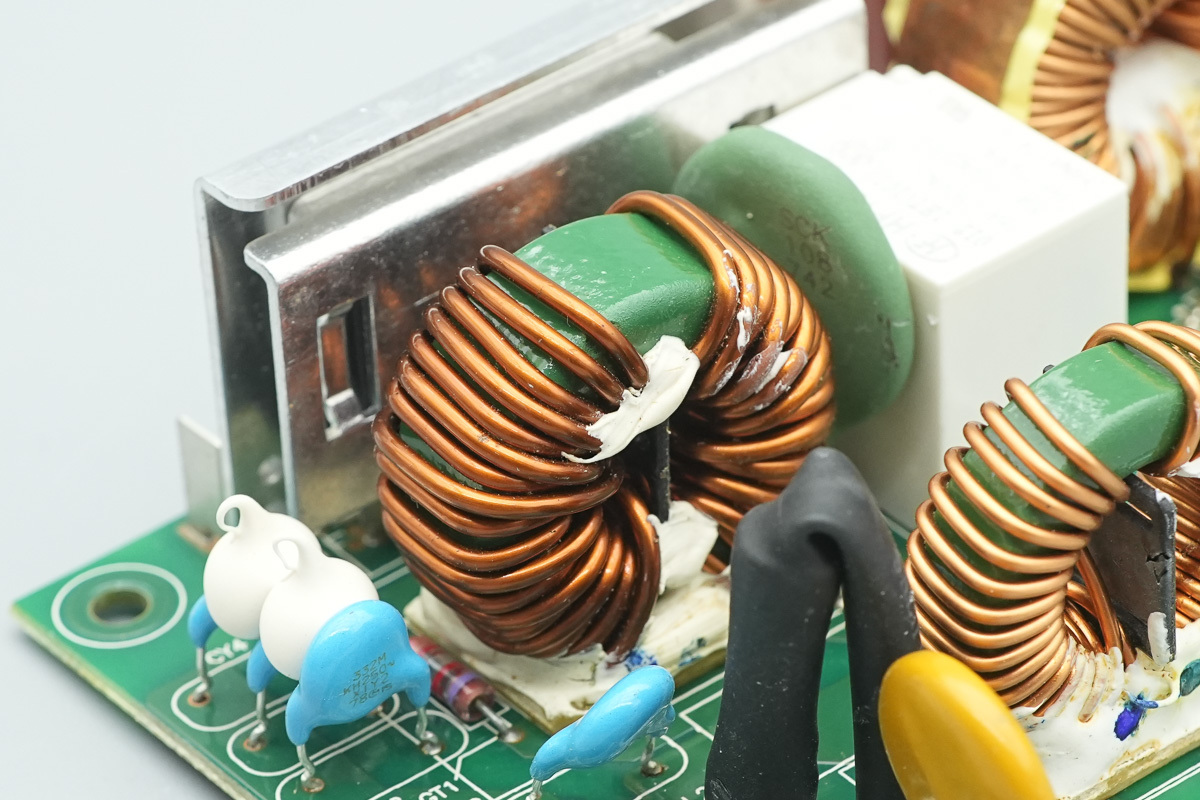
Another one is also wound with enameled wire.
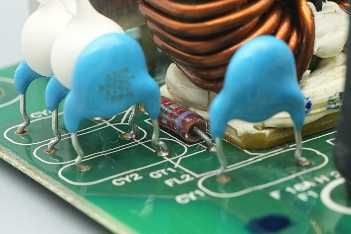
A gas discharge tube is positioned at the base of the common-mode choke.
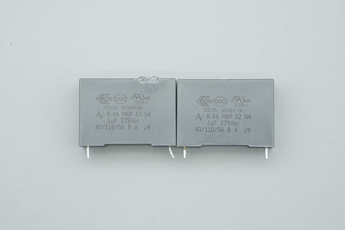
The safety X2 cap, spec 1μF.
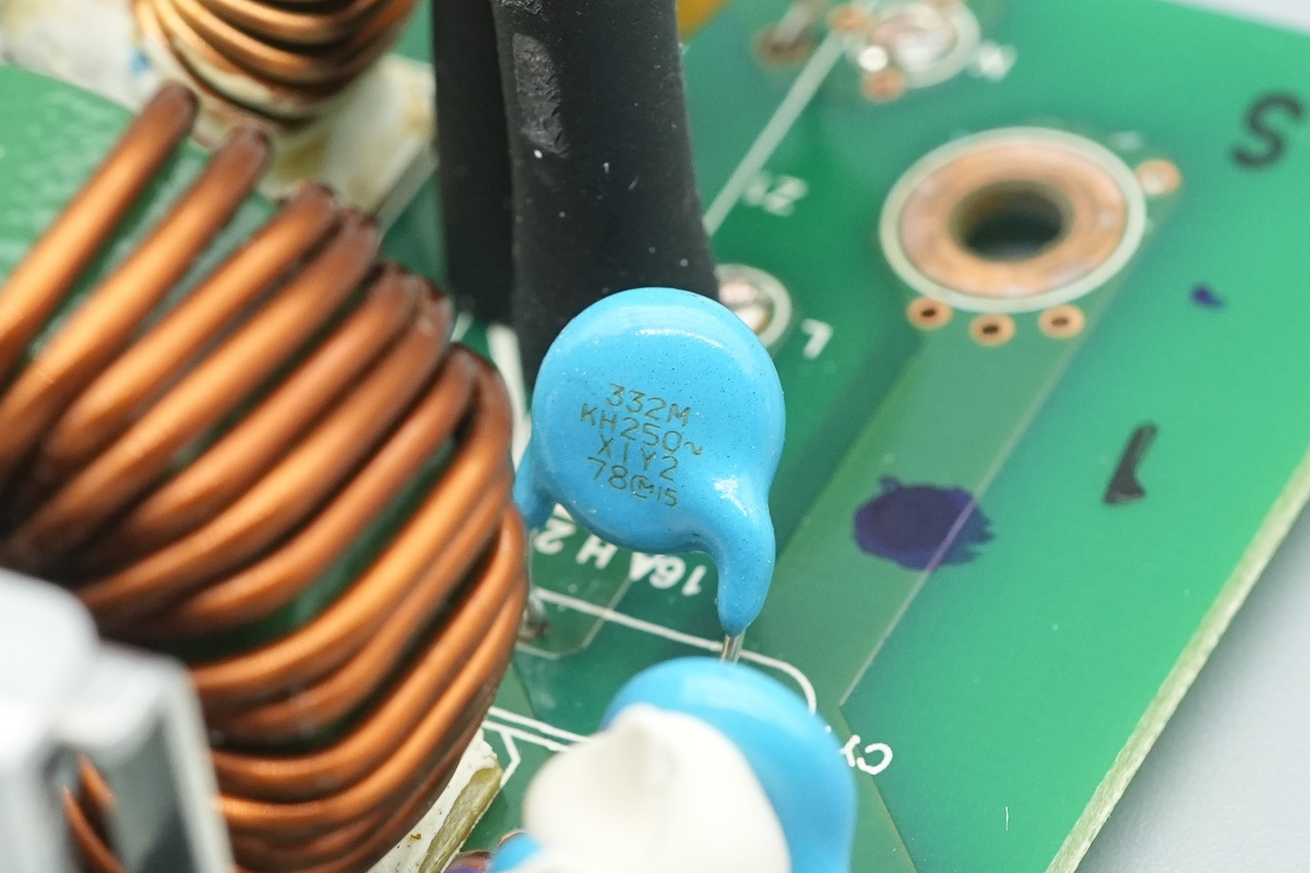
The blue Y-cap, model 332M.
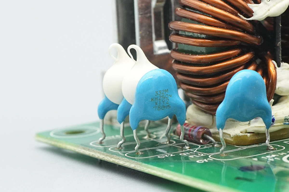
The other one shares the same model.
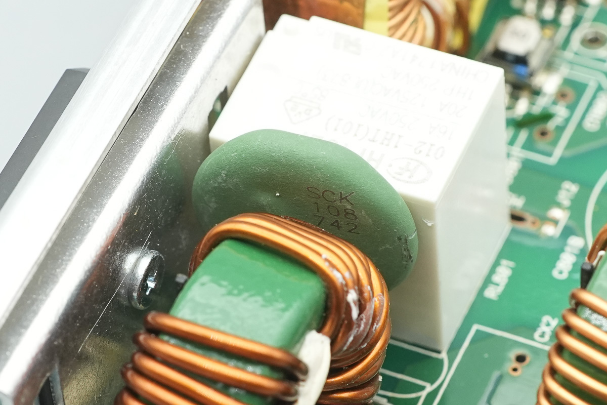
The thermistor, marked SCK 108.
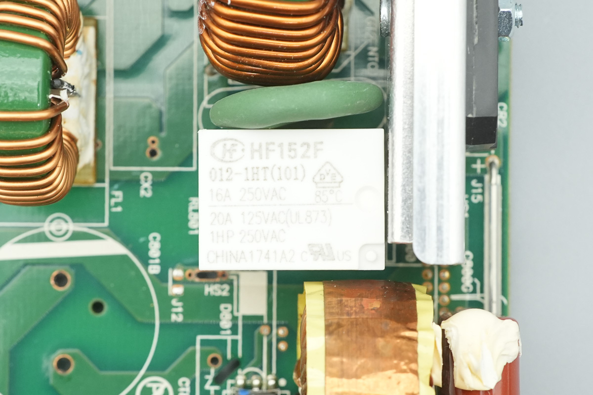
The relay is from HONGFA, model HF152F/012-1HT, which is an ultra-miniature high-power relay with a built-in normally open contact group, featuring a 20A contact switching capacity and a 12V coil voltage.
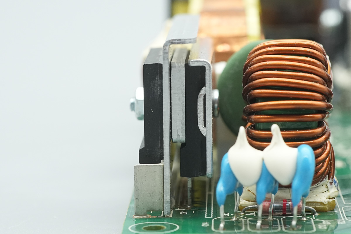
The two rectifier bridges are connected in a half-bridge configuration, with the heatsink secured by screws.
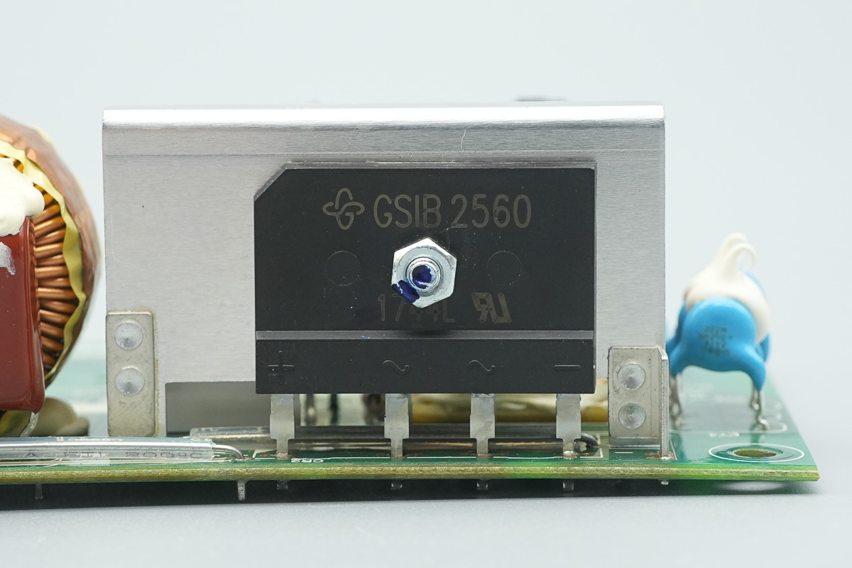
The rectifier bridge is from VISHAY, model GSIB2560, rated at 600V 25A, utilizing a GSIB-5S package.
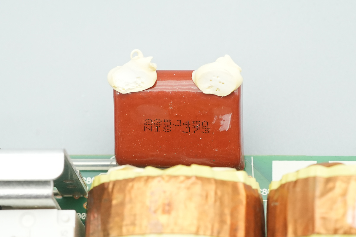
The film filter cap,spec 2.2μF 450V.
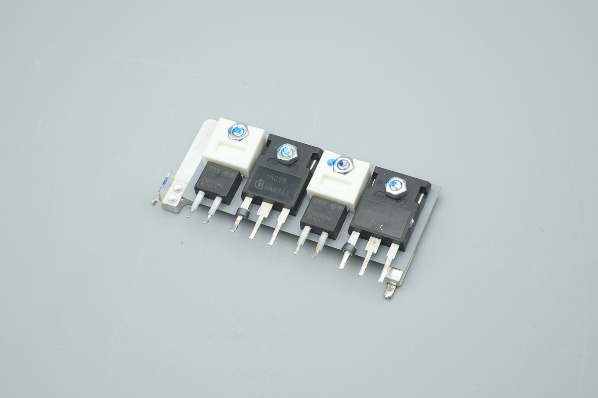
The PFC MOSFET and PFC rectifier MOSFET are secured to the heatsink.
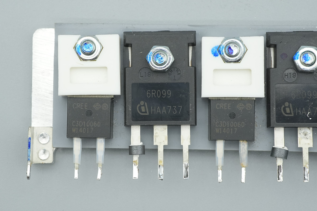
The PFC MOSFET is from Infineon, marked 6R099, model IPW60R099CP, NMOS, 650V and 99mΩ, and in a TO-247 package.
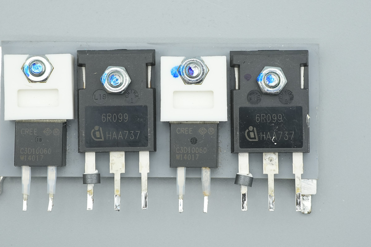
The PFC rectifier MOSFET is from Wolfspeed, model C3D10060A, which is aSiC diode rated at 600V 10A, in a TO-220-2 package.
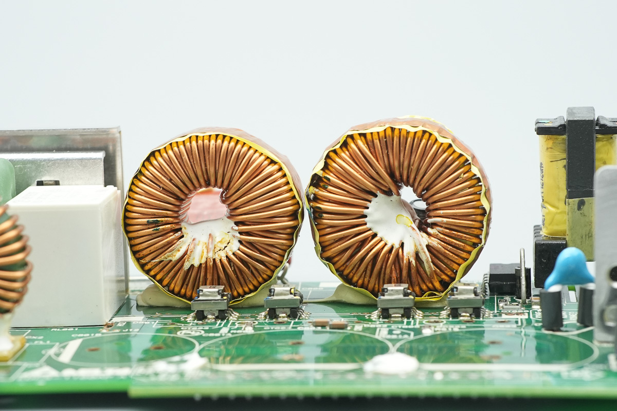
The PFC boost choke is wound with enameled wire.
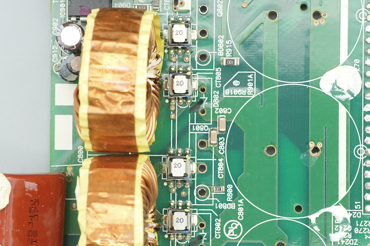
The SMD current transformers are used to detect the current of the MOSFETs and the rectifier MOSFETs.
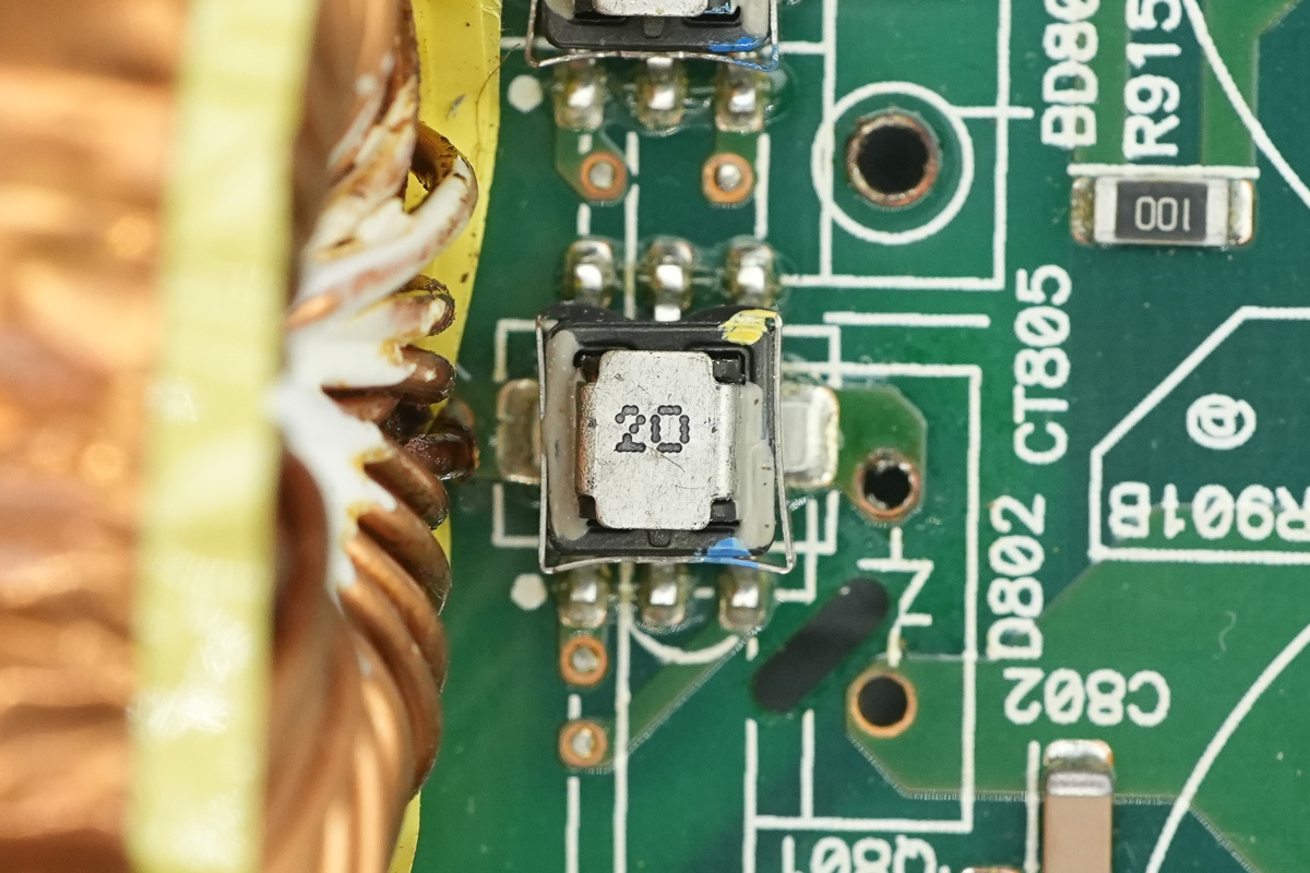
The SMD current transformer.
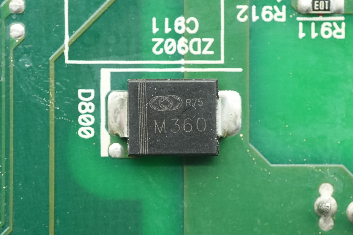
The bypass diode is from Gulf, marked M360, utilizing an SMC package.
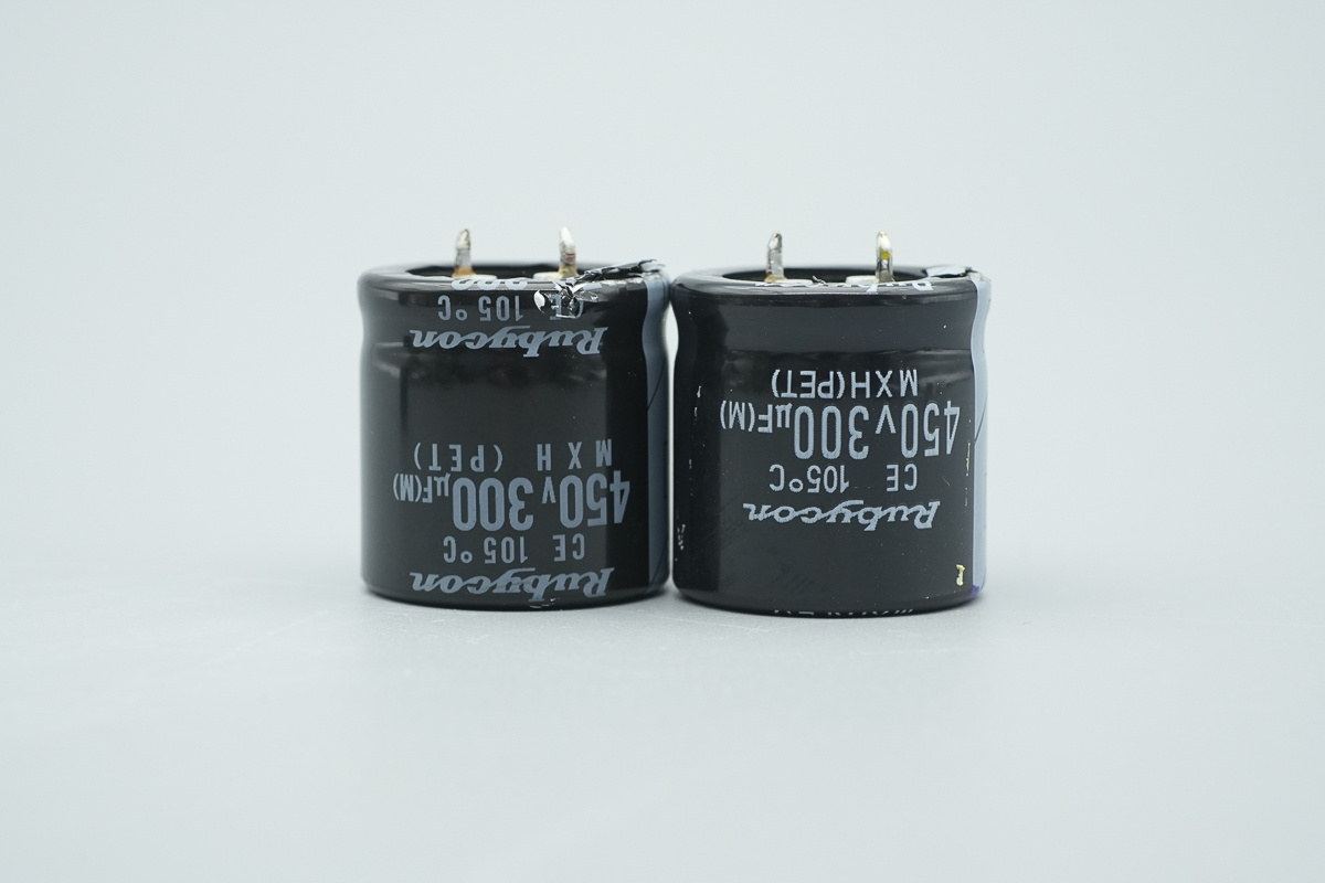
The high-voltage filter cap is from Rubycon, belonging to the MXH series electrolytic capacitor family, spec 450V 300μF.
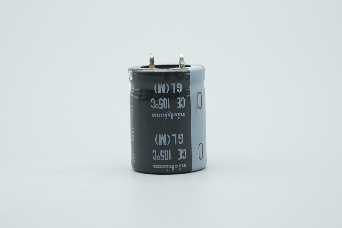
The high-voltage filter cap is from Nichicon, belonging to the LGL series ultra-miniature electrolytic capacitor family.
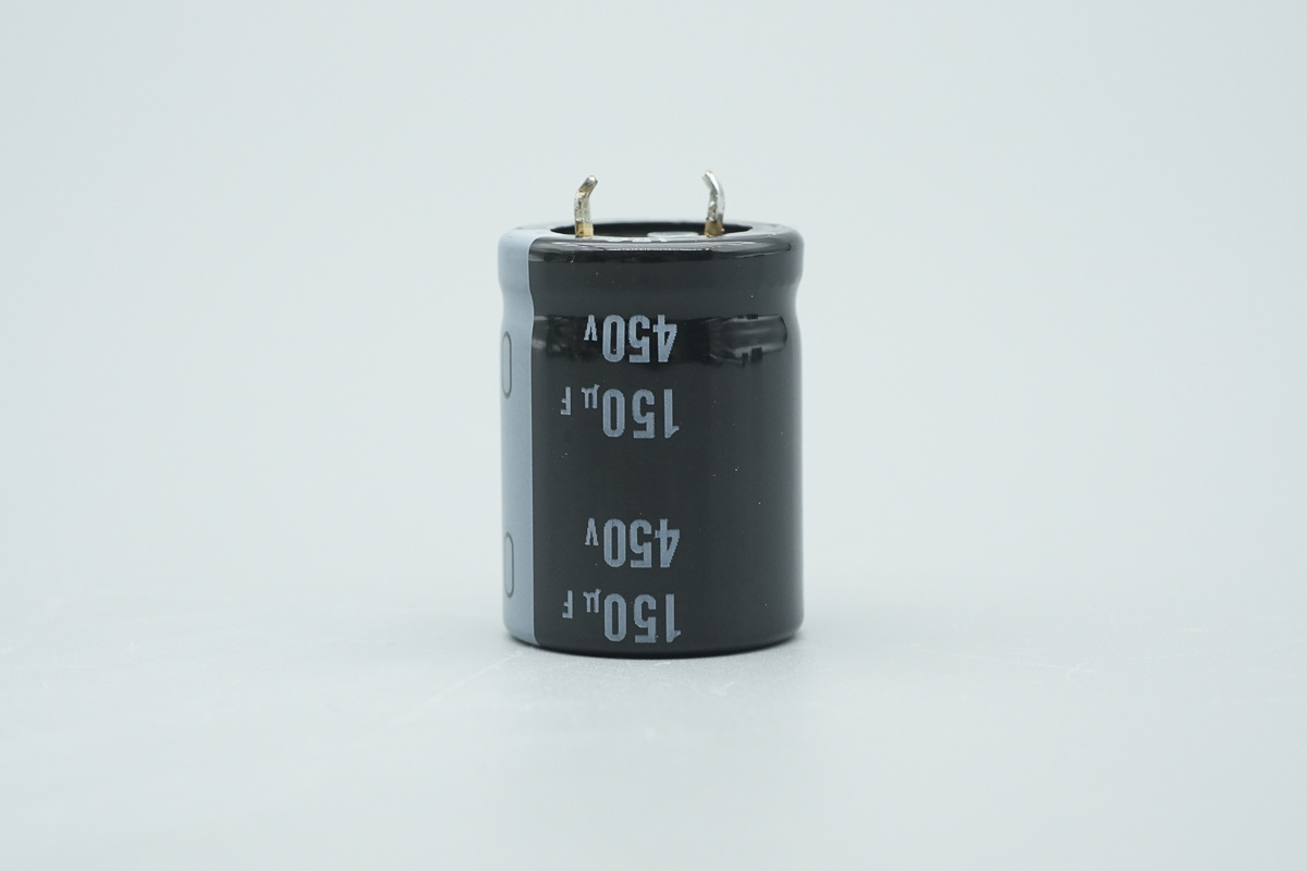
The spec is 150μF 450V.
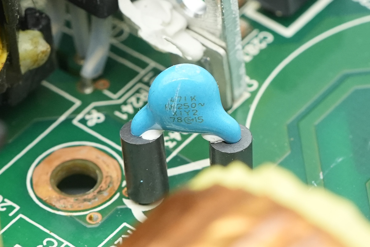
The blue Y-cap, model 471K.
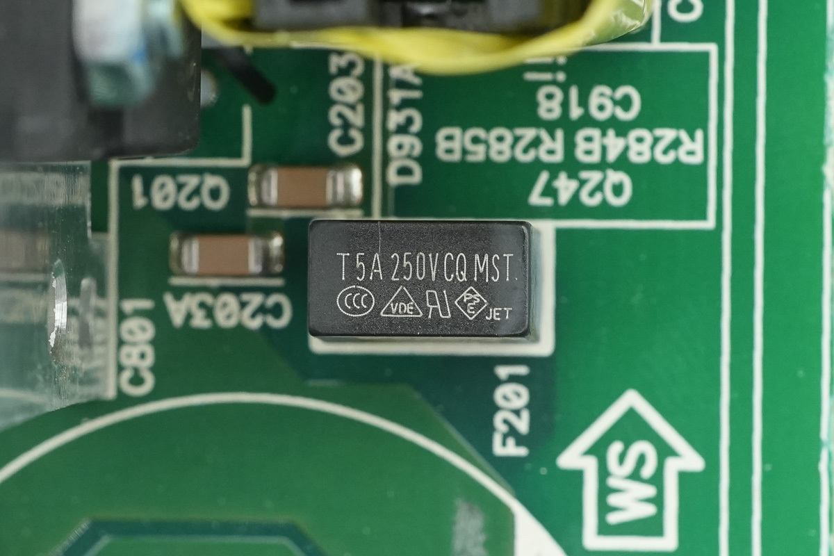
The fuse is from Conquer, spec 5A 250V, used for OCP of the phase-shifted full-bridge circuit.
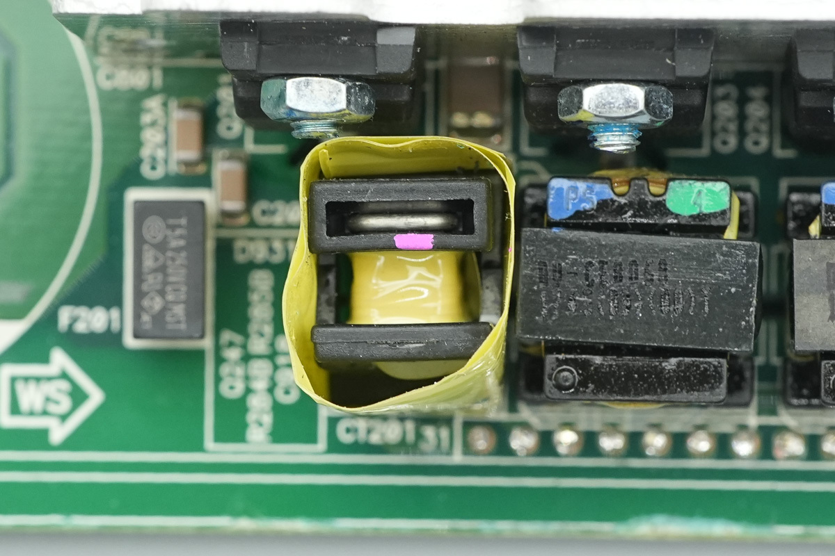
The current transformer is insulated by wrapping with adhesive tape.
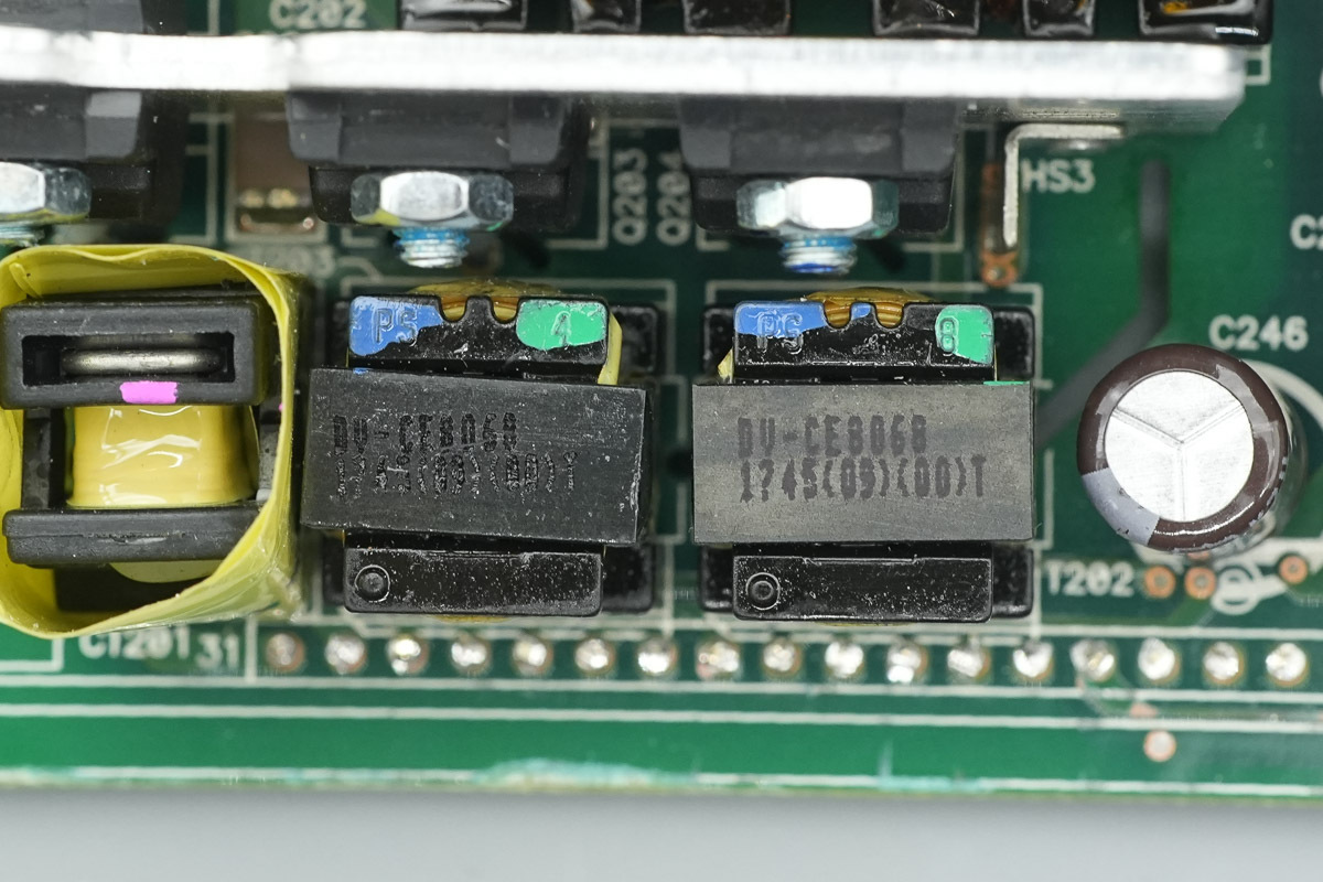
There are the isolated drive transformers.
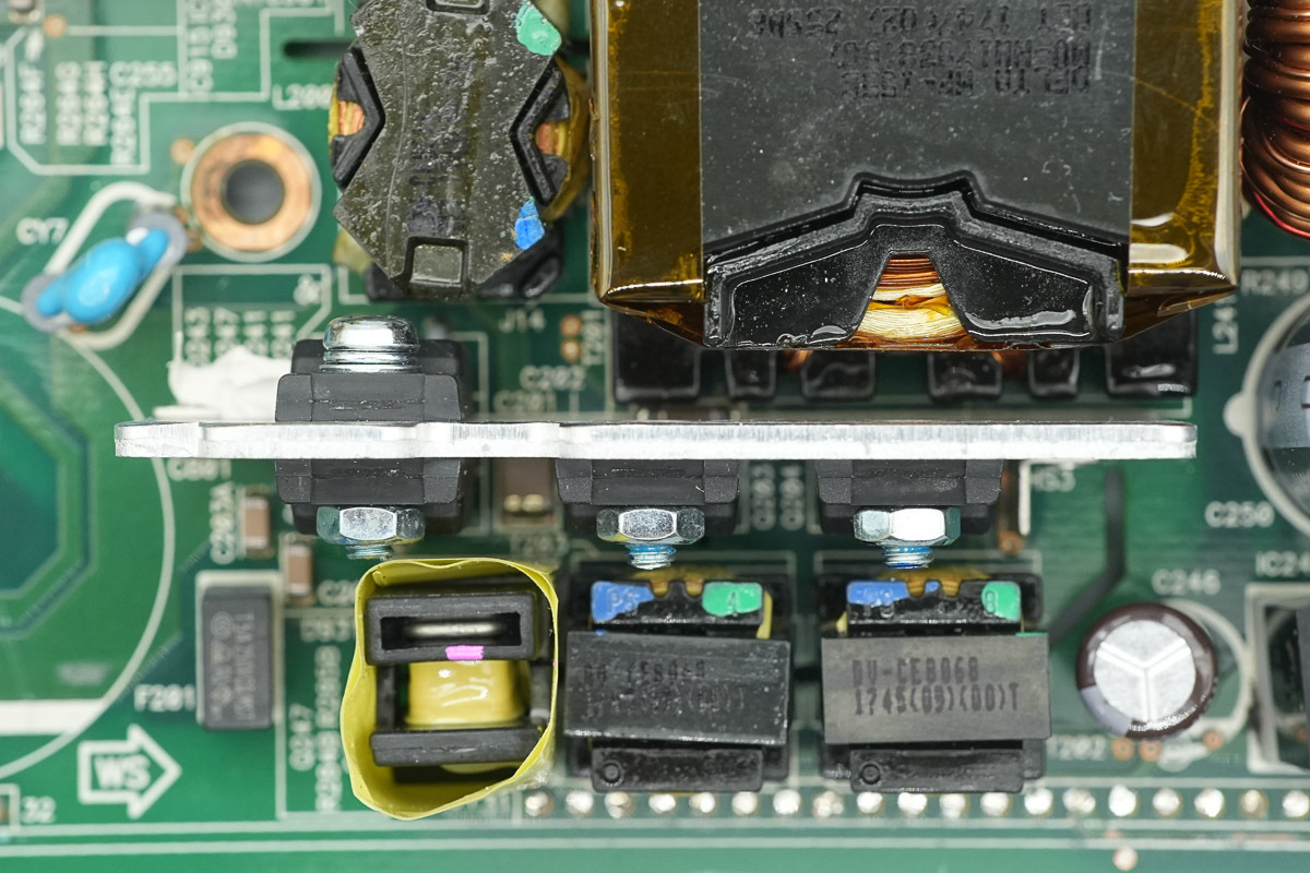
The heatsink secures the phase-shifted full-bridge switching MOSFETs.
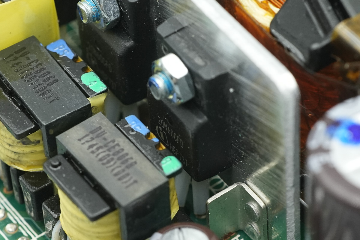
The phase-shifted full-bridge switching MOSFETs are from Infineon, model SPA20N60CFD, NMOS, 600V and 220mΩ, and in a TO-220 package.
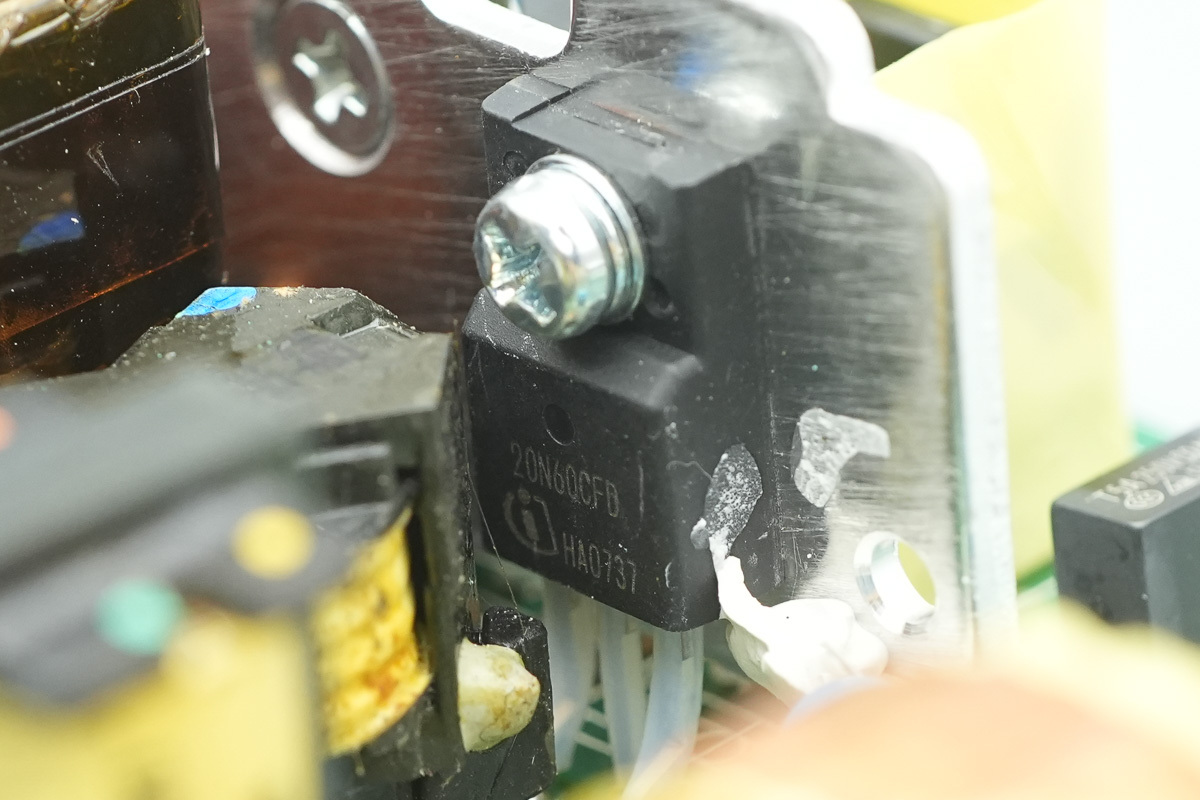
A total of four phase-shifted full-bridge switching MOSFETs share the same model.
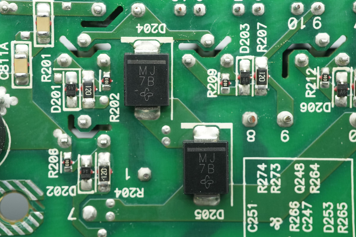
The two diodes are from VISHAY, marked MJ, model MURS360, which are fast recovery diodes utilizing an SMC package.
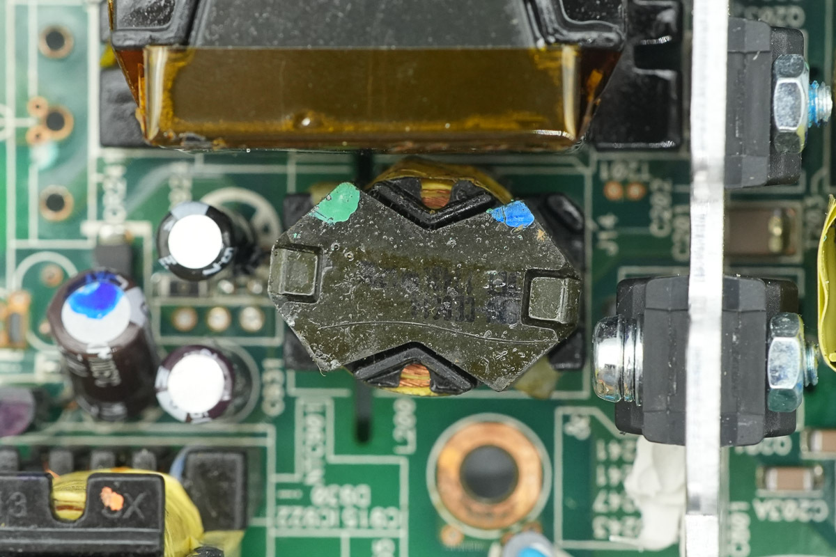
The resonant choke is wound with Litz wire.
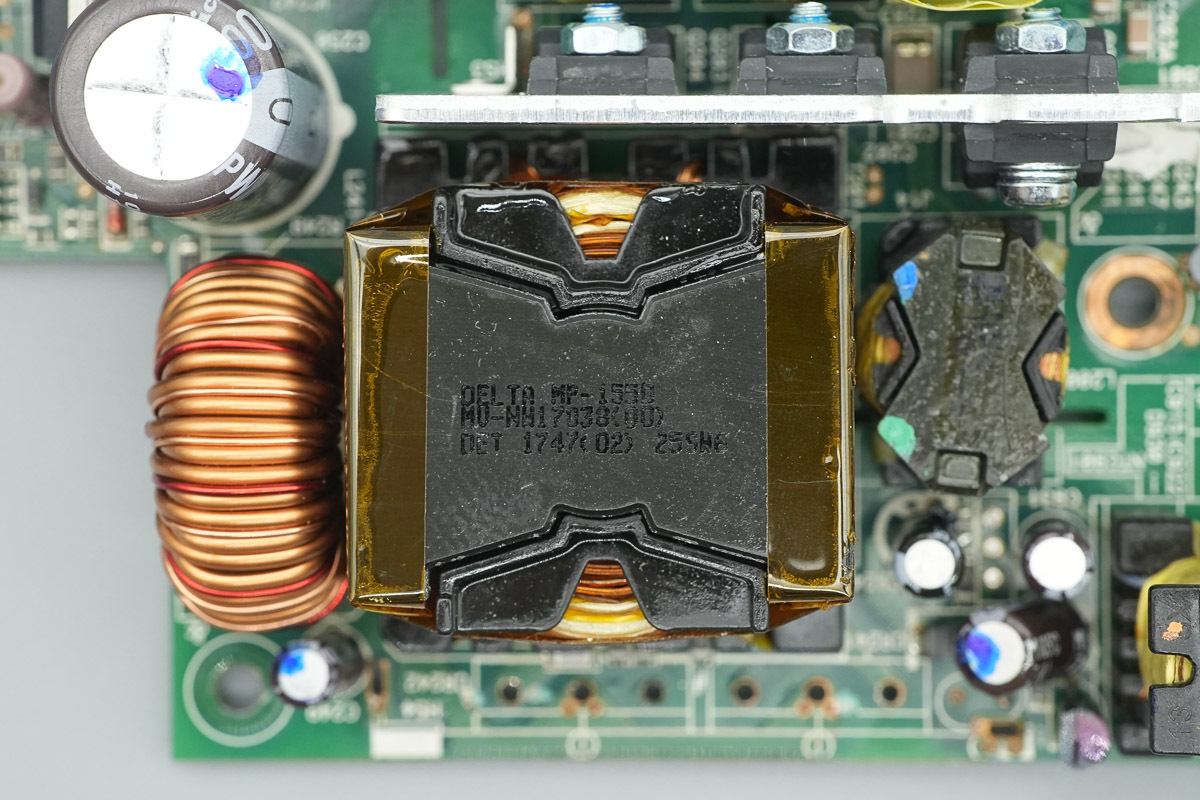
The transformer core is insulated by wrapping with high-temperature adhesive tape.
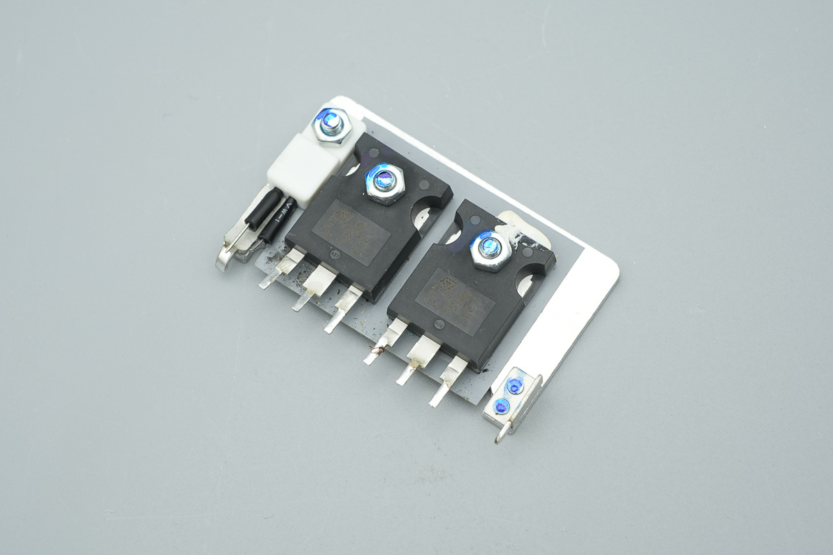
The rectifier MOSFETs and thermistor are secured to the heatsink.
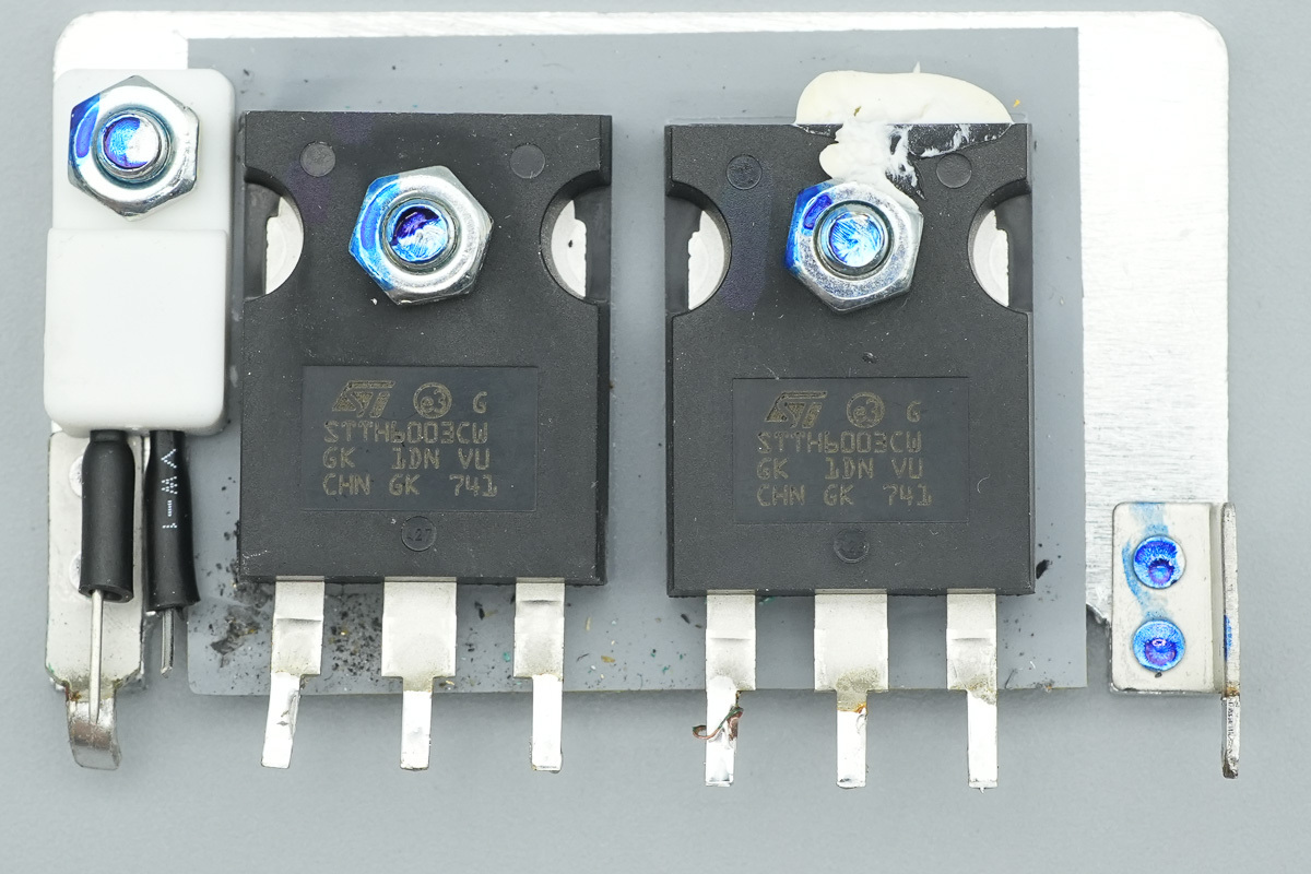
The rectifier MOSFETs are from ST, model STTH6003CW, which are high-frequency diodes rated at 300V 60A, utilizing a TO-247 package.
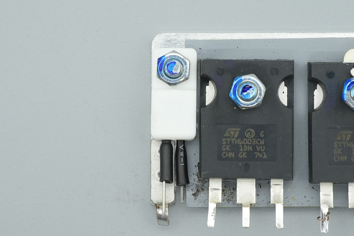
The thermistor is secured via a clamping plate.
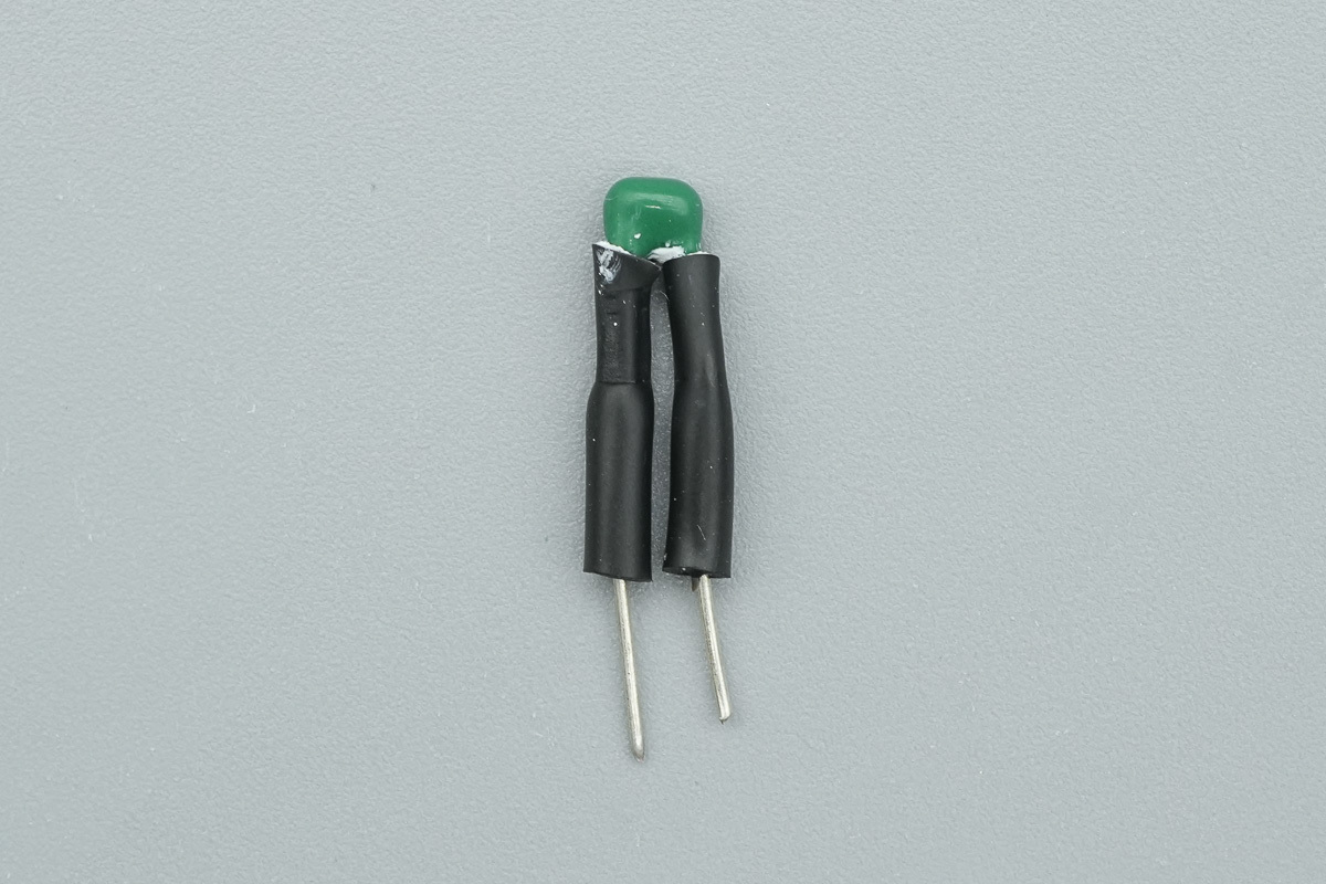
This is the thermistor used for detecting heatsink temperature.
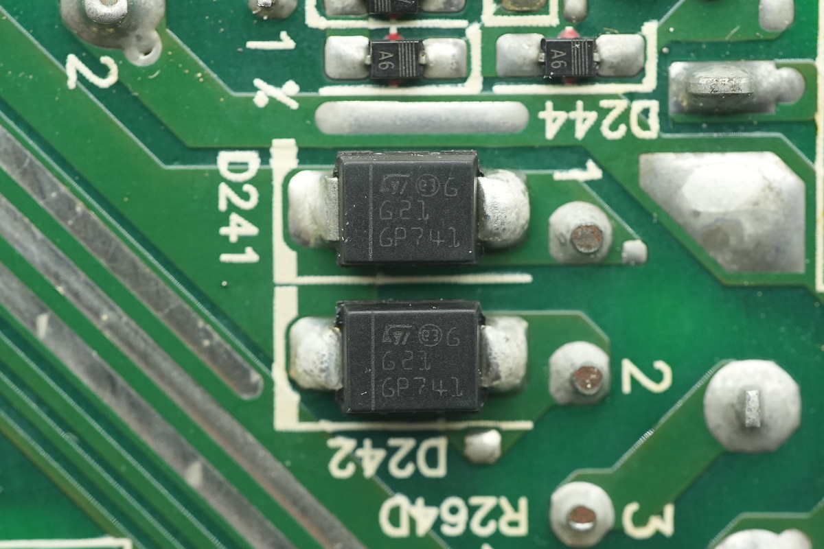
The diodesare from ST, marked G21, model STPS2H100U, rated at 2A 100V, utilizing an SMB package.
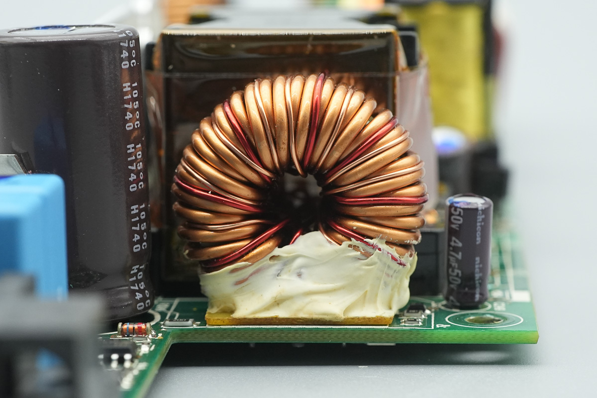
The filtering choke is wound with enameled wire, with a Bakelite bottom plate reinforced with potting compound.
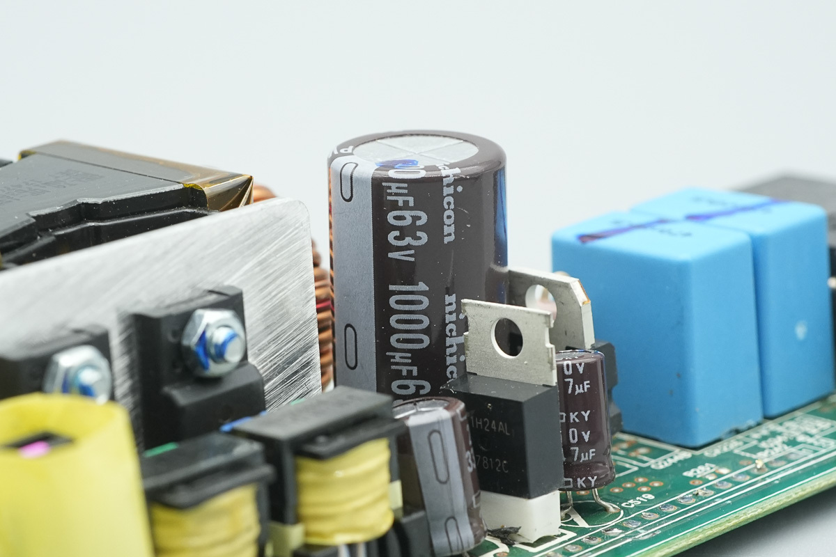
The filtering cap,spec 1000μF 63V.
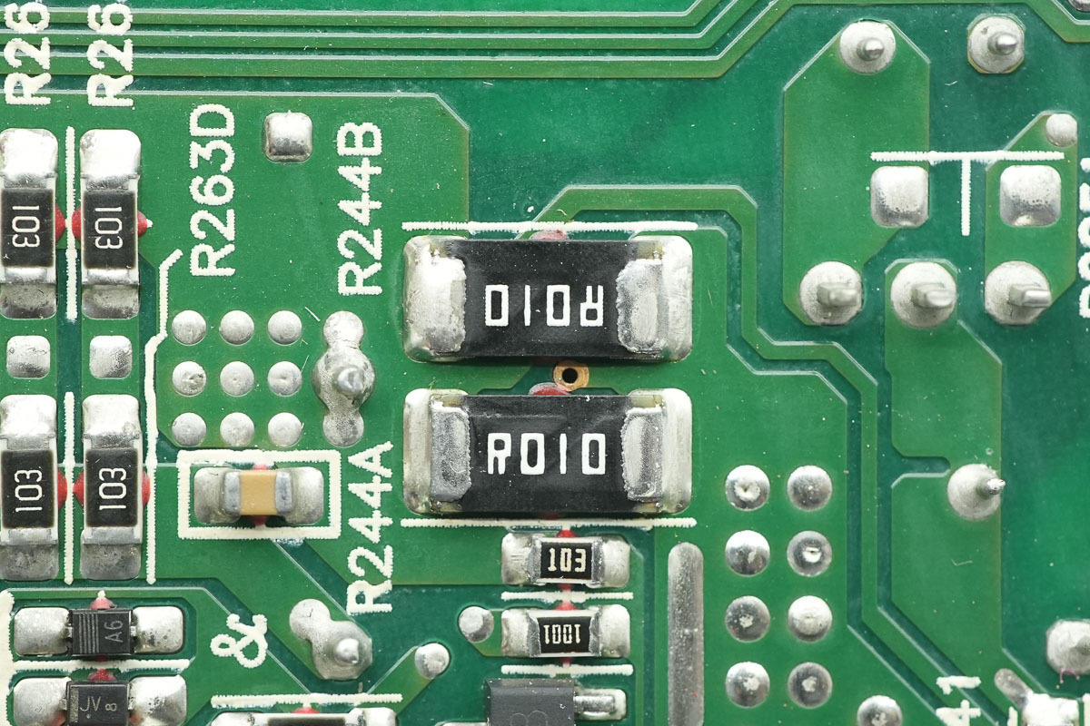
Two 10mΩ resistors are connected in parallel and used for output current detection.
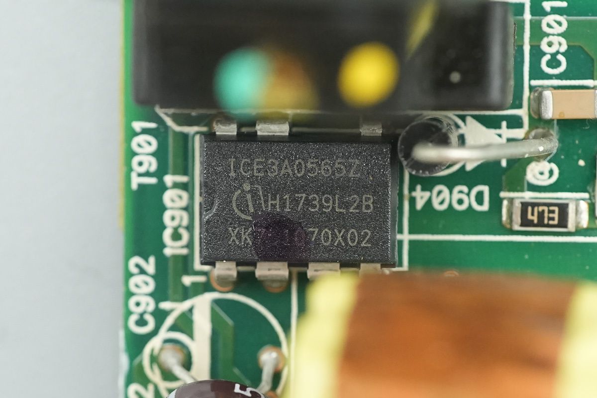
The auxiliary power supply chip is from Infineon, model ICE3A0565Z, which is a current-mode PWM controller for switching power supplies, integrating a high-voltage startup cell and a 650V breakdown voltage switching MOSFET, utilizing a DIP-7 package.
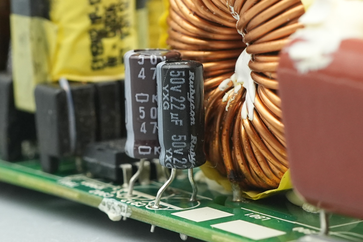
The power supply filter cap is from Rubycon, spec 50V 22μF.
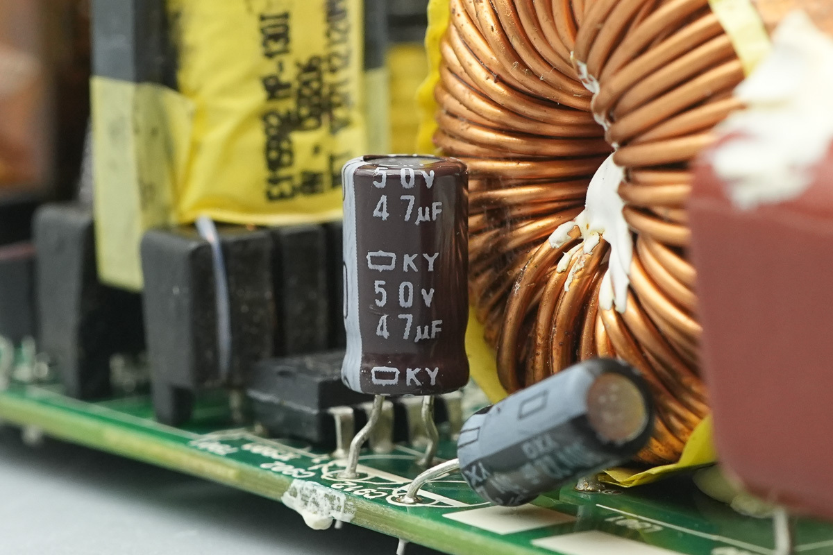
Another one is from NCC, spec 50V 47μF.
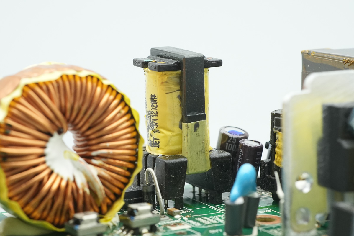
The auxiliary power transformer.
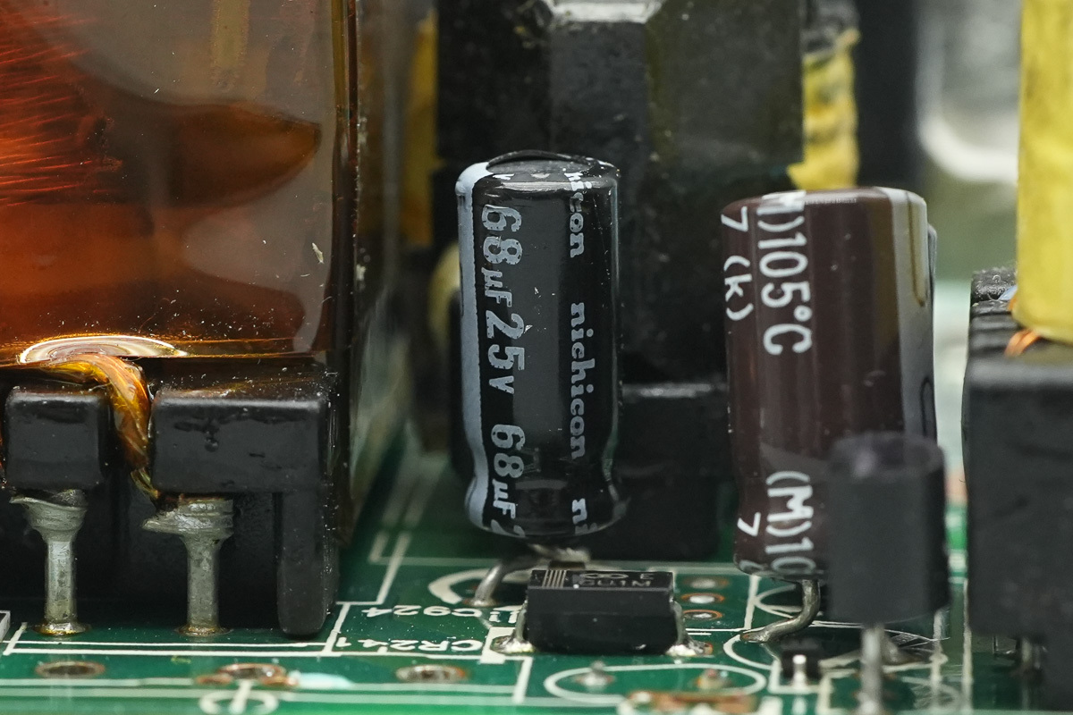
The filtering cap is from Nichicon, spec 68μF 25V.
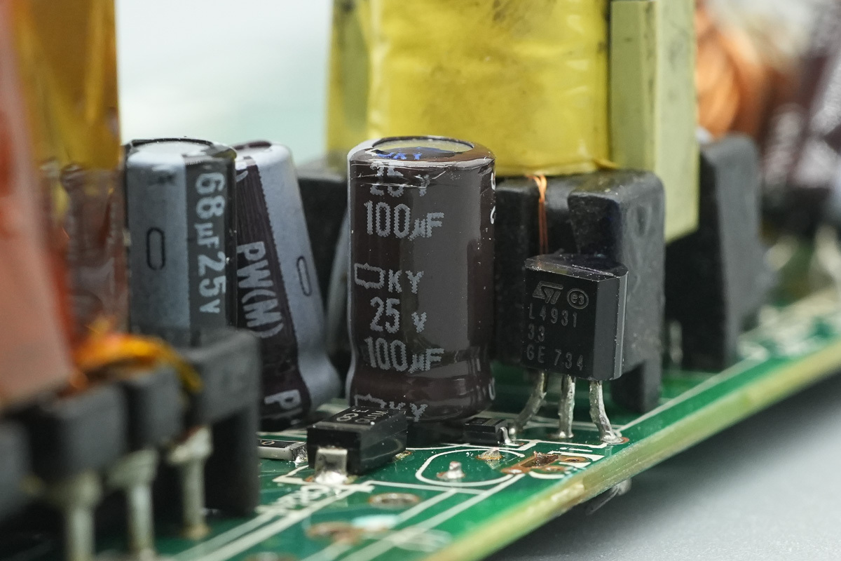
The filtering cap,spec 25V 100μF.
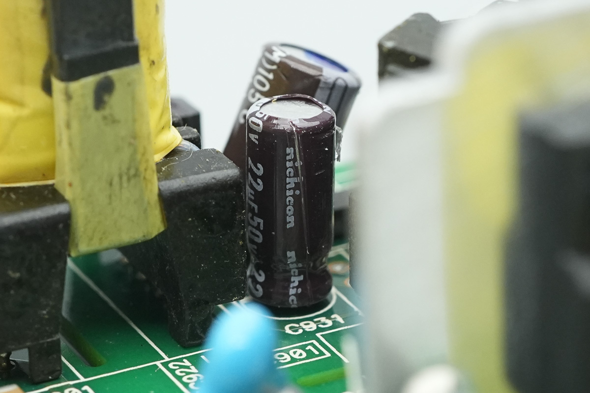
The filtering cap, spec 22μF50V.
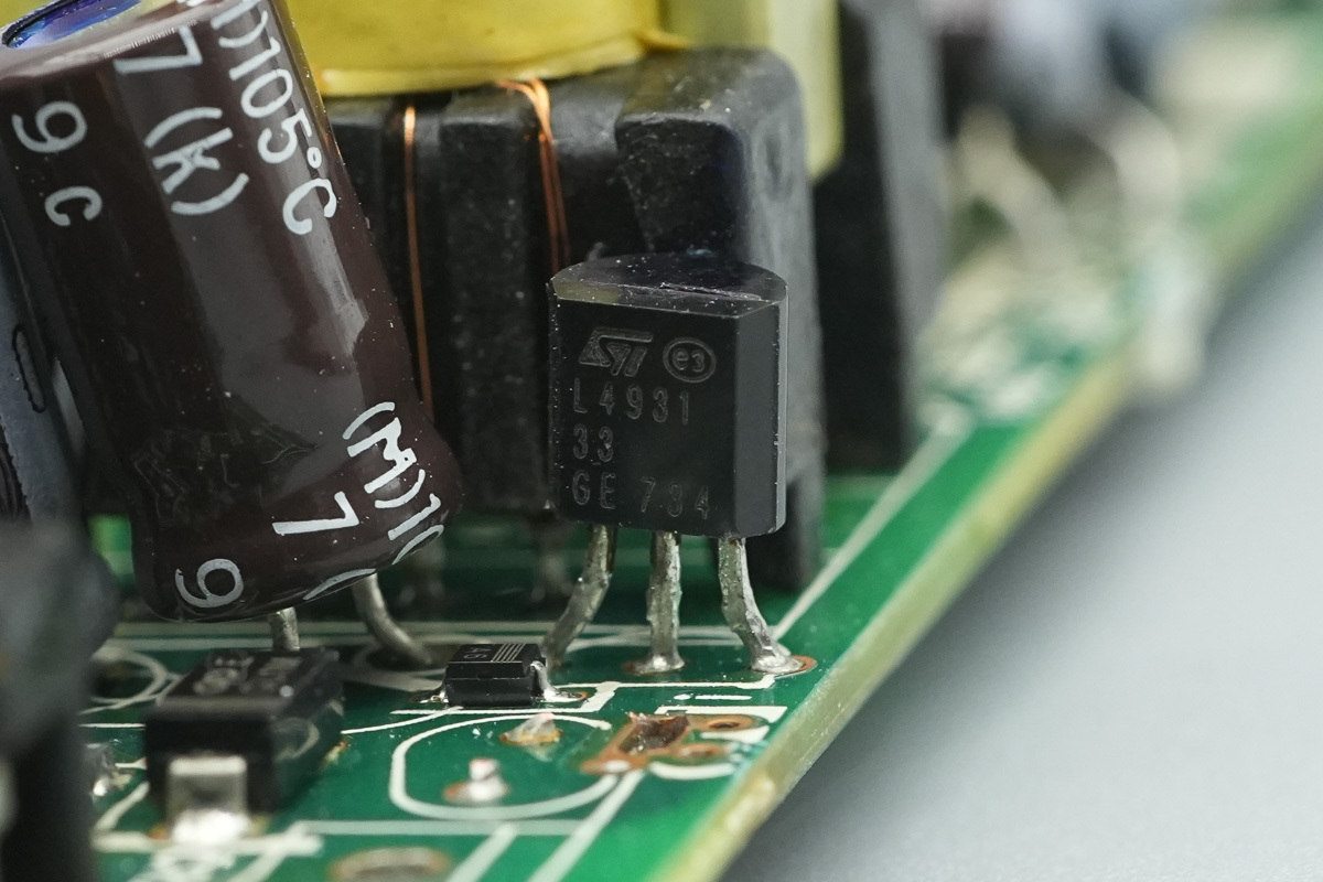
The voltage regulator chip is from ST, model L4931CZ33, supporting a 20V input voltage, a 3.3V output voltage, a 250mA output current, and in a TO-92 package.
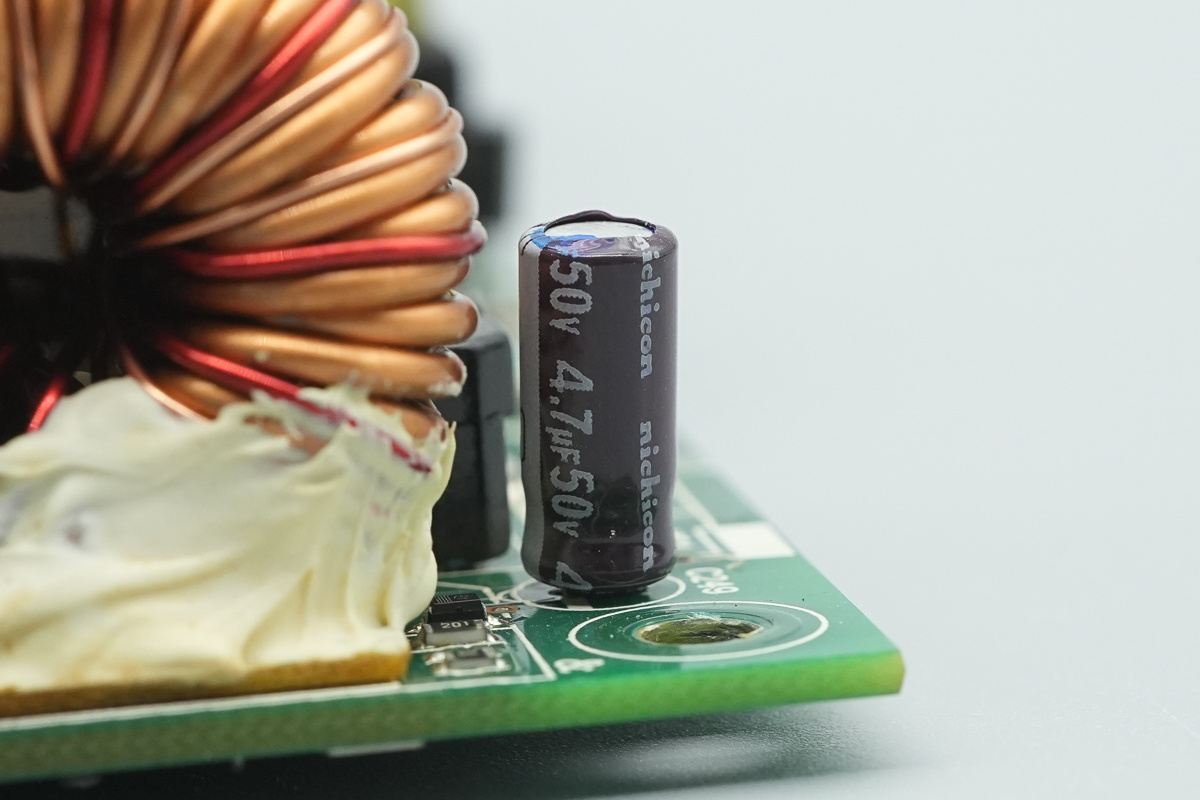
The filtering cap, spec 4.7μF 50V.
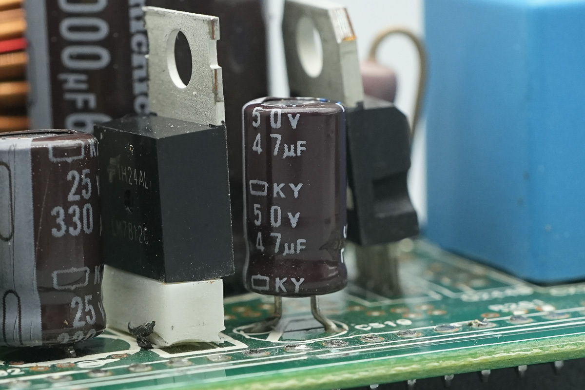
The filtering cap is from NCC, spec 50V 47μF.
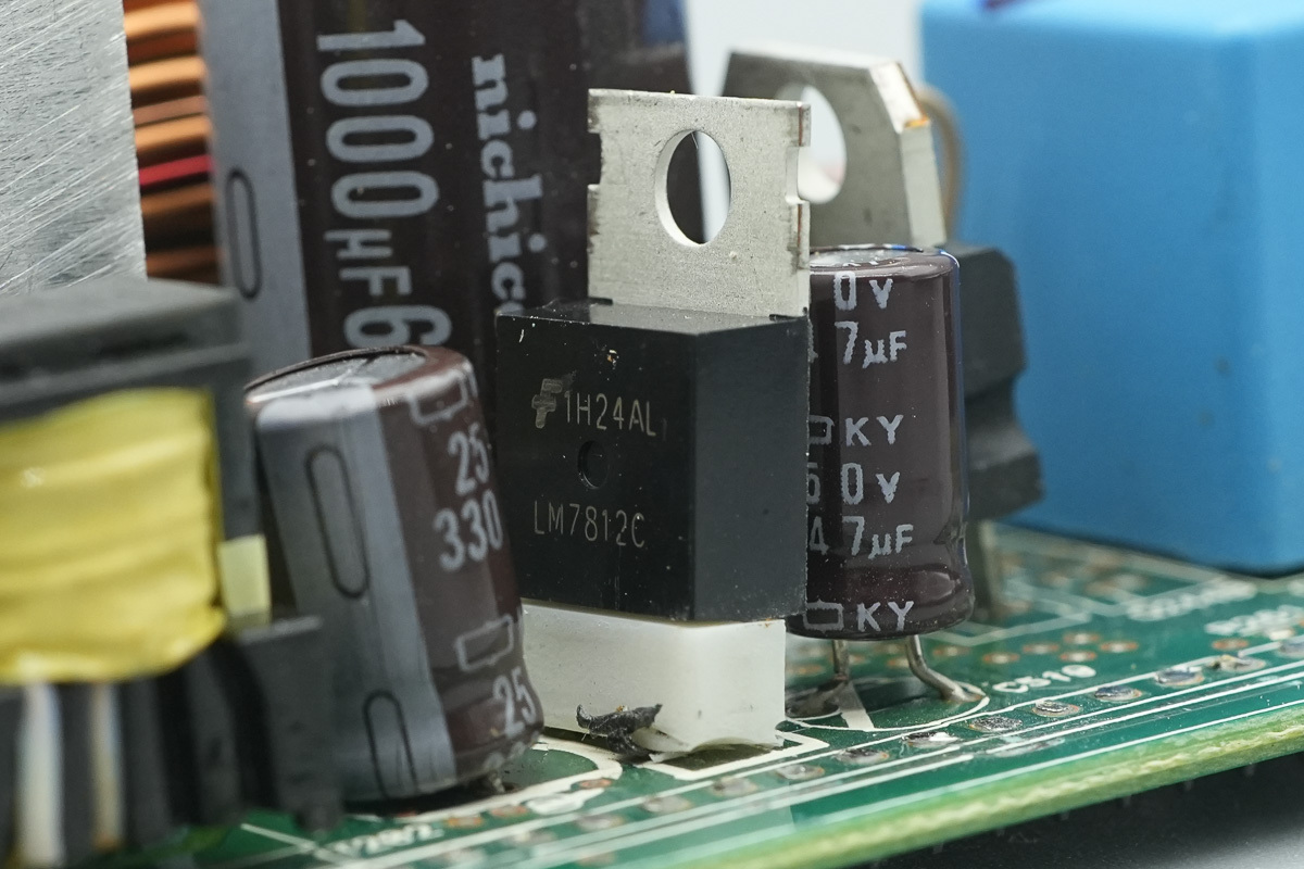
The voltage regulator chip is from onsemi, model LM7812C, supporting a 35V input voltage, a 12V output voltage, a 1A output current, and in a TO-220 package.
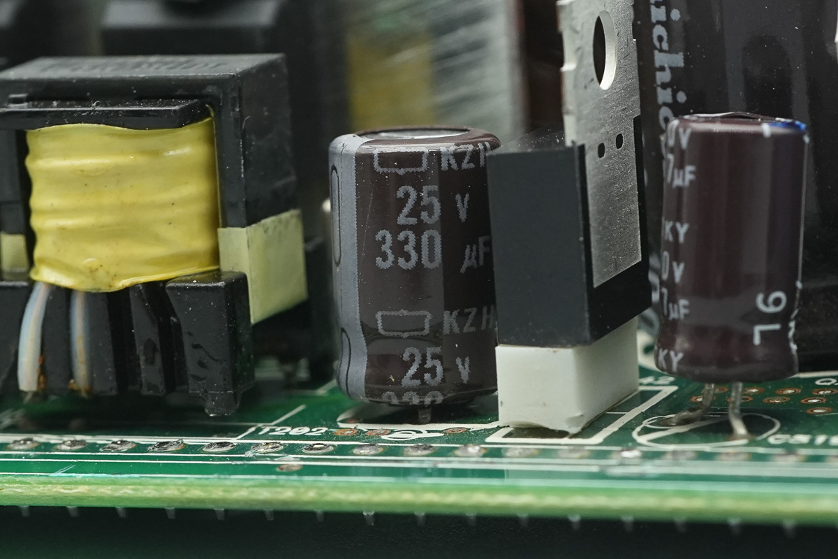
The filtering cap,spec 25V 330μF.
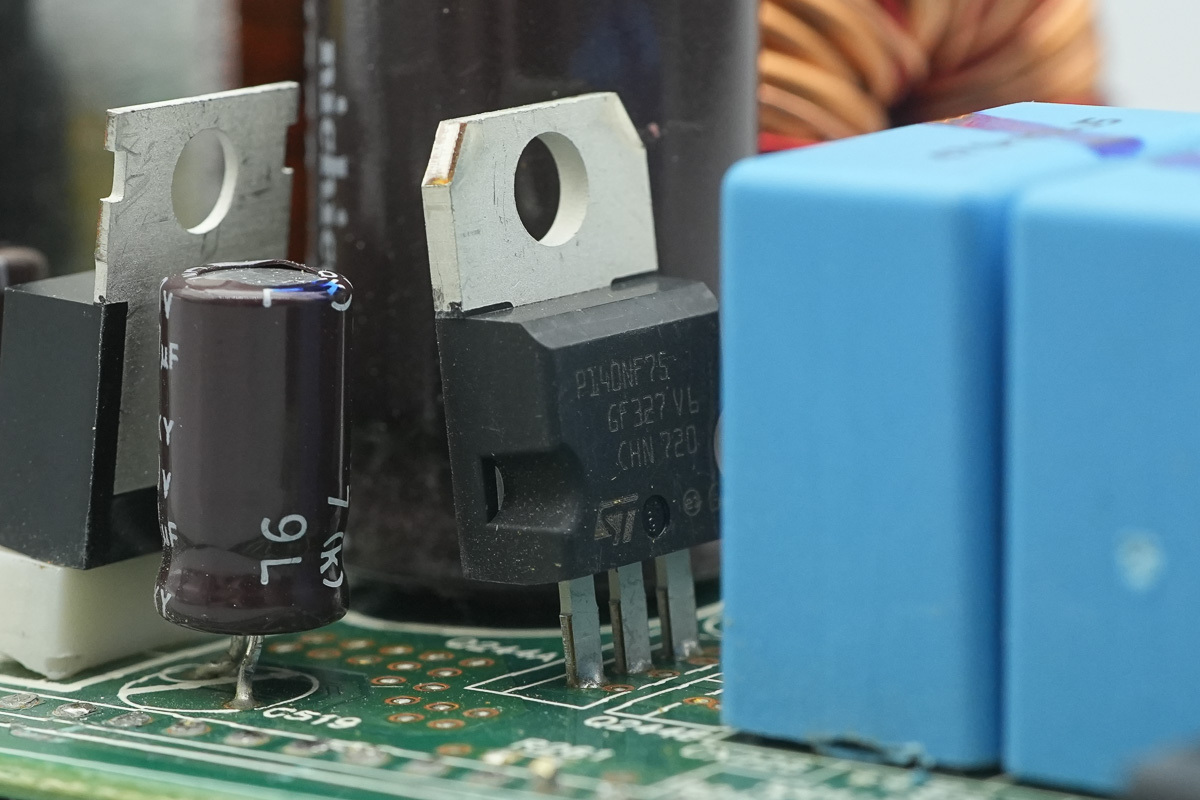
The switching MOSFET is from ST, model STP140NF75, NMOS, 75V and 6.5mΩ, and in a TO-220 package.
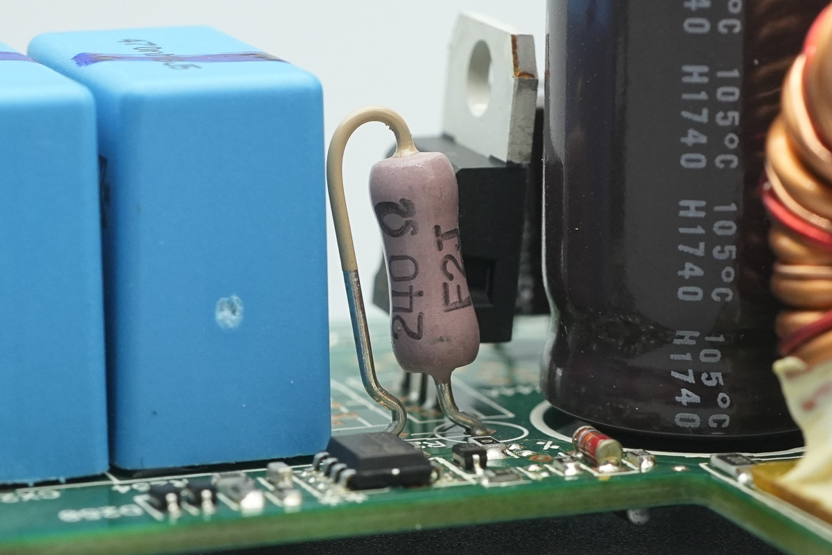
There is a 240Ω discharge resistor.
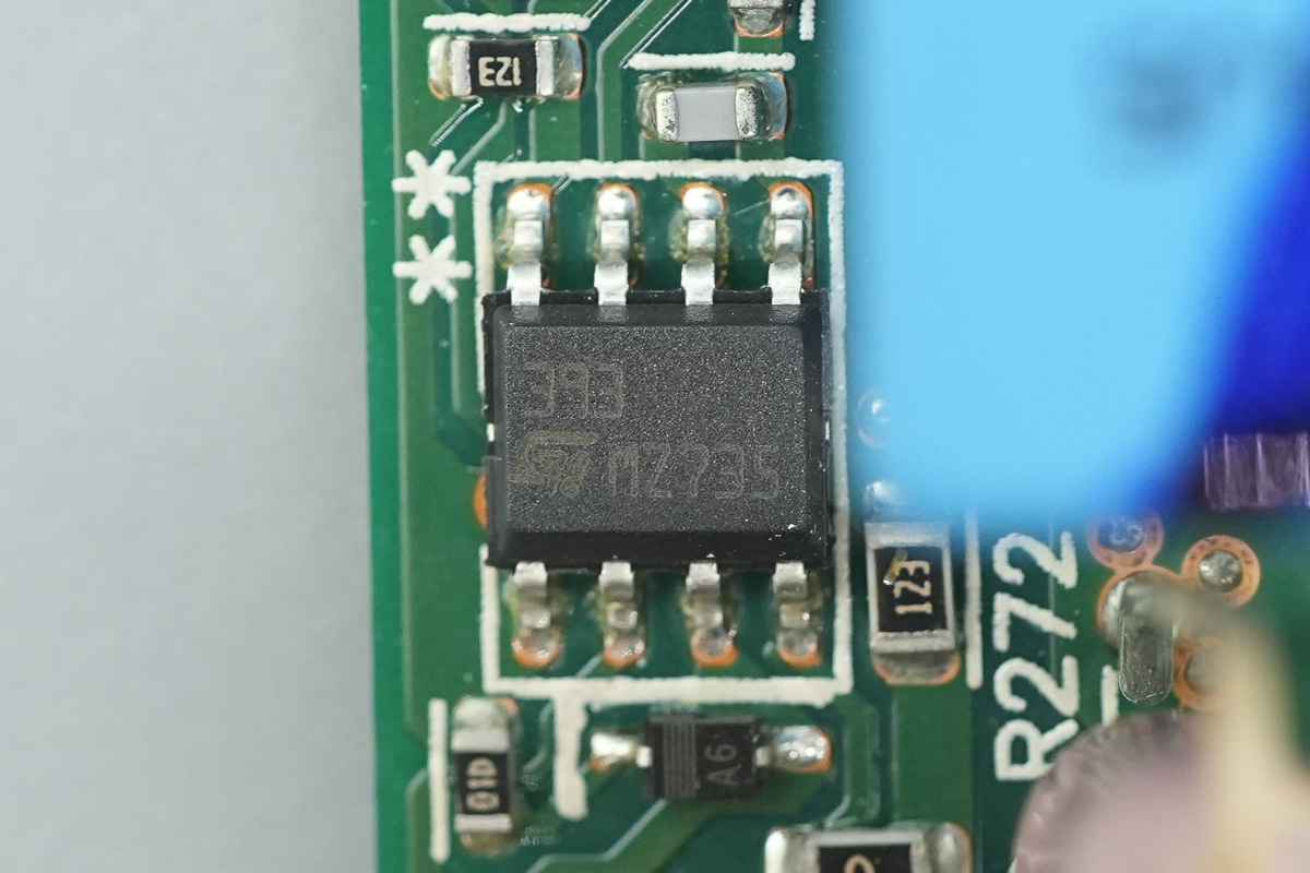
The voltage comparator is from ST, model LM393, which is a low-power dual voltage comparator utilizing an SO-8 package.
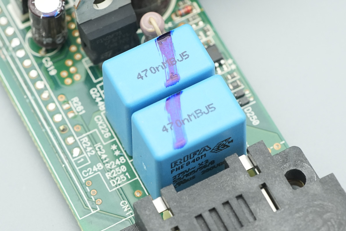
The two X2 safety caps, spec 4.7μF.
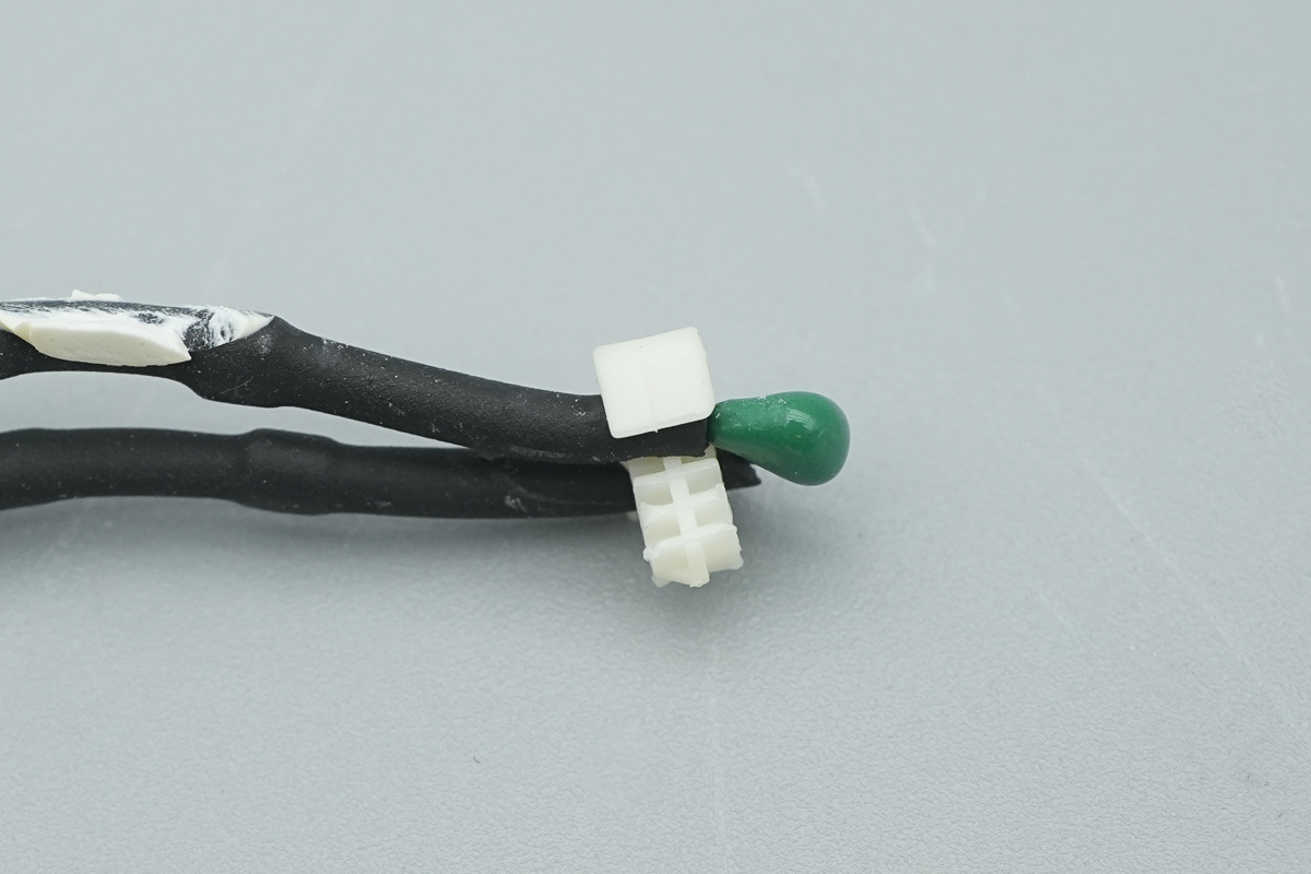
The thermistor used for temperature detection.
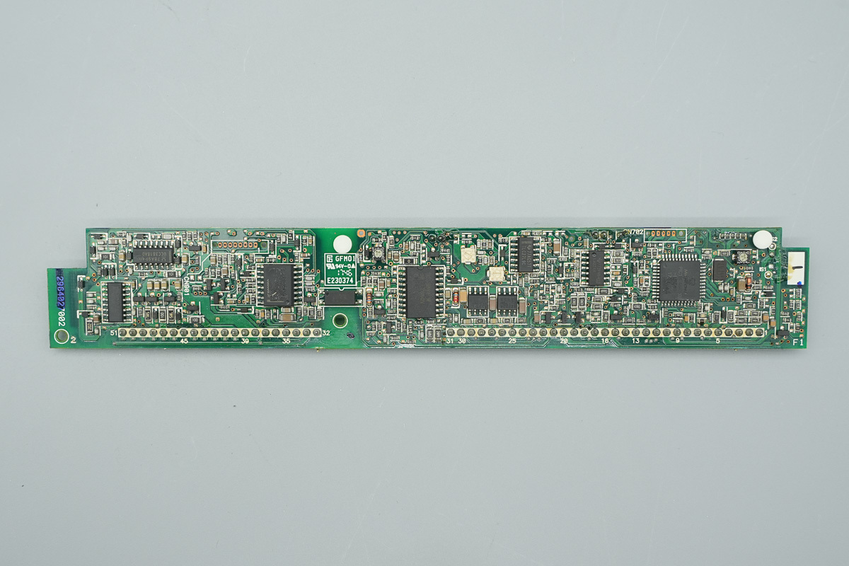
The outside of the control PCB features a PFC controller, MCU, phase-shifted full-bridge controller, driver, and operational amplifier.
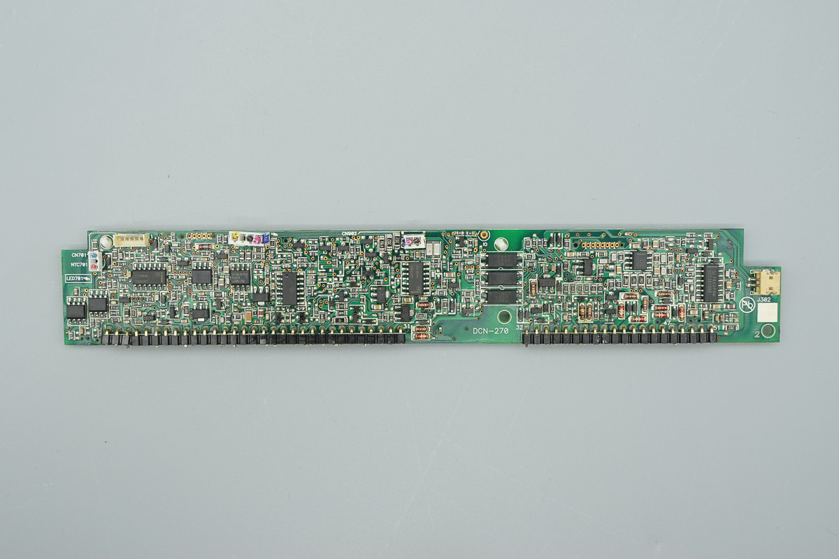
The inside features a PFC controller, operational amplifier, memory, voltage comparator, and feedback optocoupler.

The PFC controller is from TI, model UCC3818AD, operating in CCM using average current mode control, featuring precise power limiting and OVP, and in a SOIC-16 package.
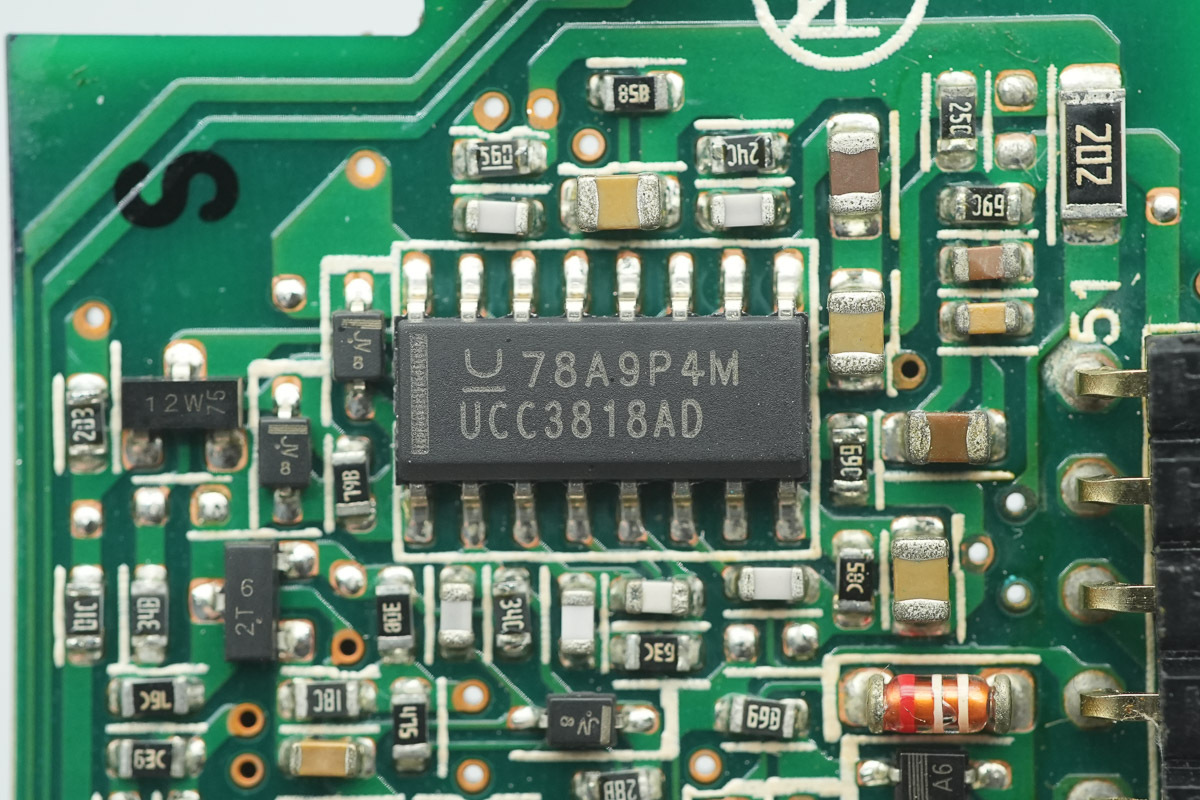
Another one of the same model is located on the other side.
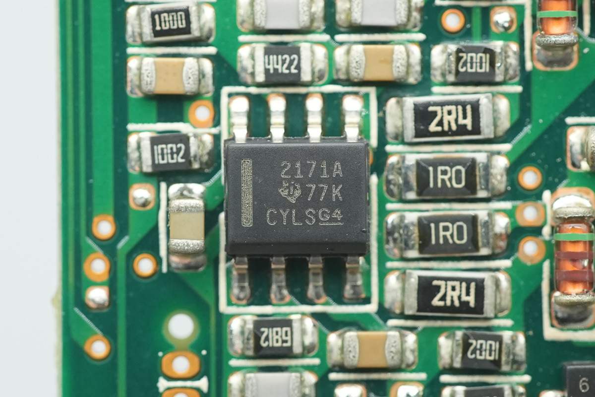
The operational amplifier is from TI, model OPA2171, which is a dual low-power operational amplifier supporting a 36V supply voltage and utilizing a SOIC-8 package.
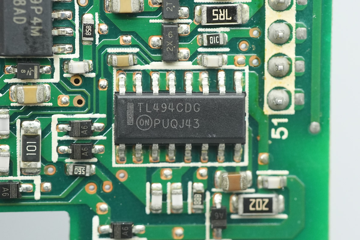
The PWM controller is from onsemi, model TL494, which is a pulse-width modulation control circuit utilizing a SOIC-16 package.
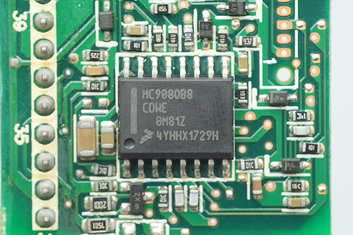
The MCU is from NXP, model MC908QB8CDWE, featuring an 8-bit MCU core, 8KB of built-in Flash and 192 bytes of RAM, supporting 5V and 3V operating voltages, equipped with a 10-channel 10-bit ADC and an SPI interface, utilizing a SOIC-16 package.
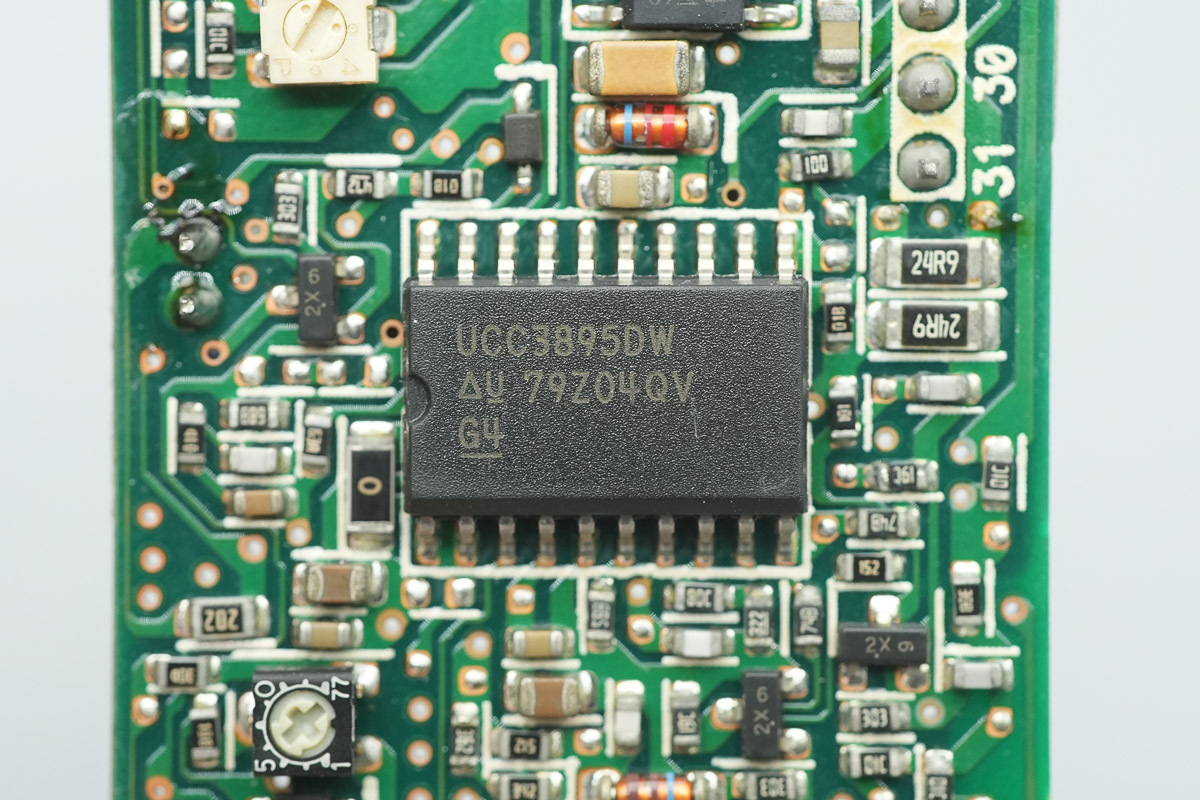
The phase-shifted full-bridge controller is from TI, model UCC3895, supporting constant frequency pulse-width modulation and resonant zero-voltage switching, as well as voltage-mode and current-mode control. It features enhanced control logic, adaptive delay setting, and shutdown functions, utilizing a SOIC-20 package.
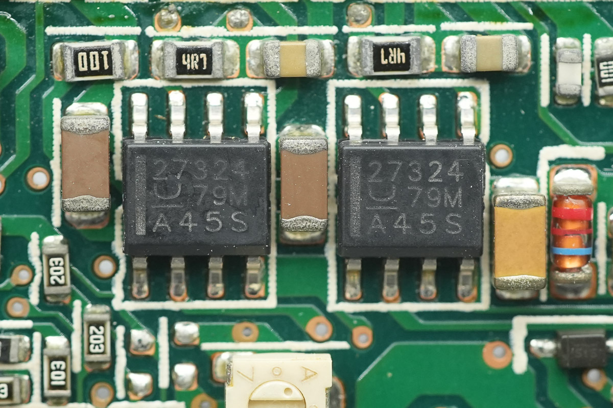
The driver is from TI, model UCC27324, which is a dual low-side gate driver featuring a 4A output current and utilizing an SOIC-8 package.
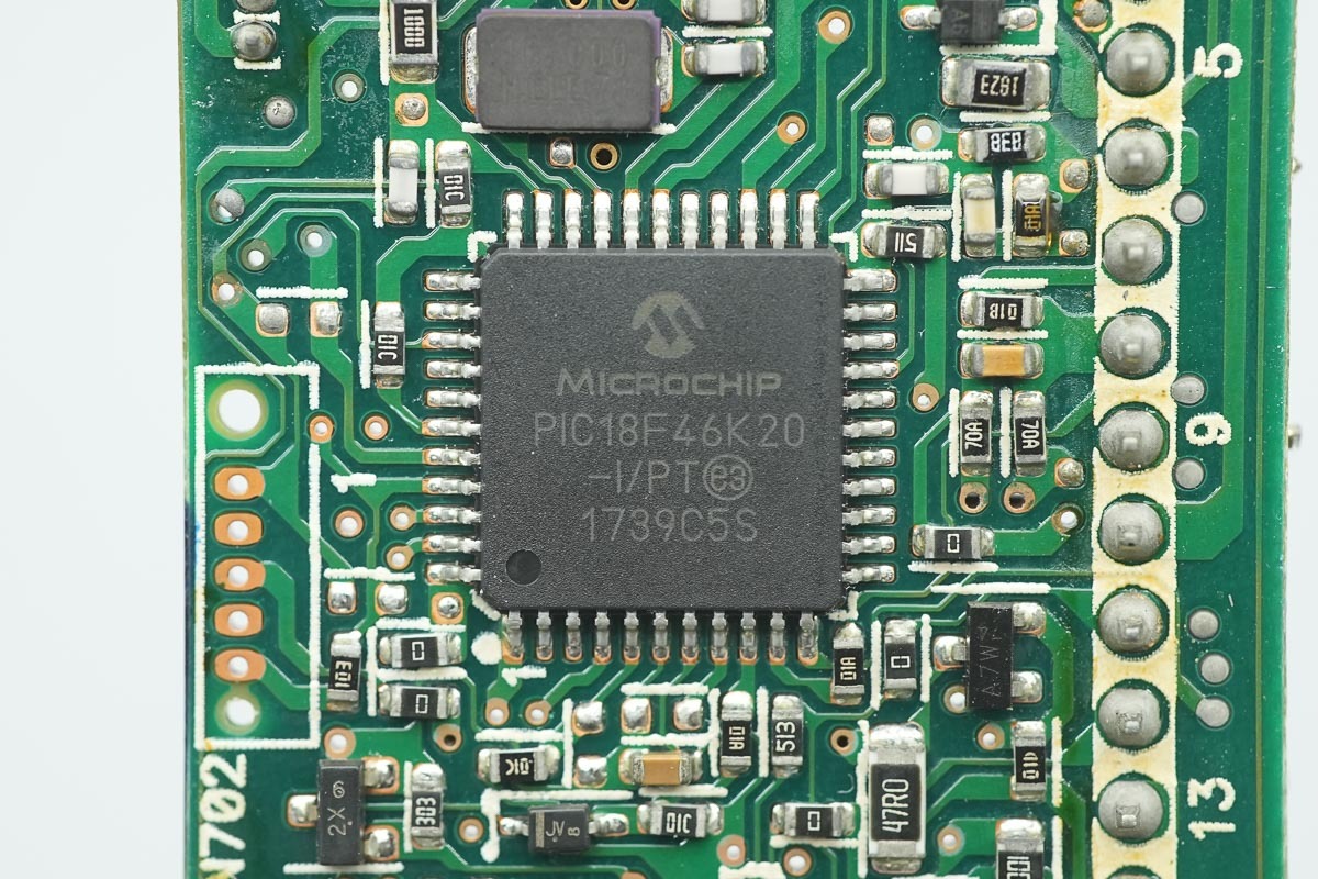
The master control MCU is from Microchip, model PIC18F46K20, featuring a high-performance RISC core CPU, 64KB of built-in Flash, 3936 bytes of RAM, 1KB of EEPROM memory, built-in ADC and DAC, and utilizing a TQFP-44 package.
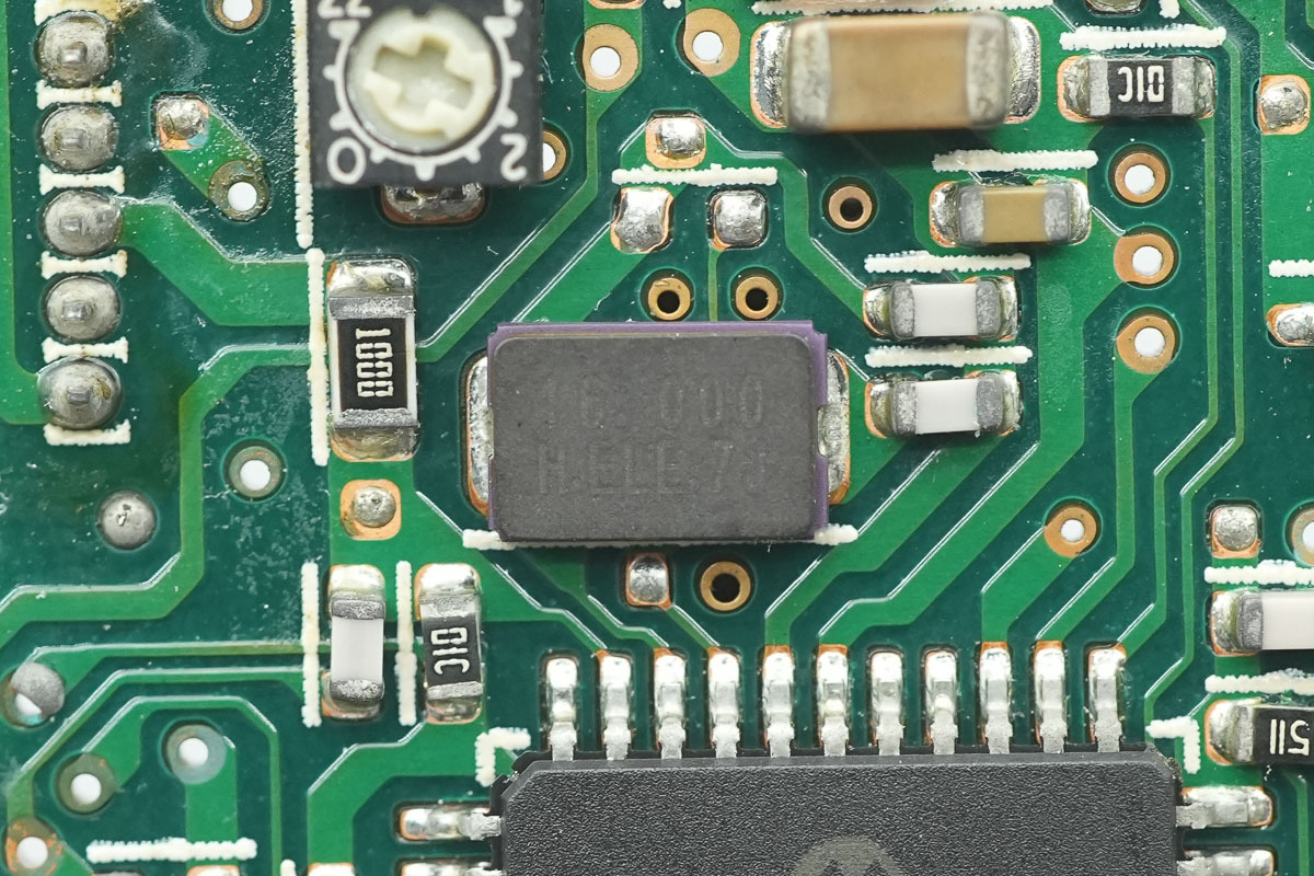
This is the 16.000MHz crystal oscillator.
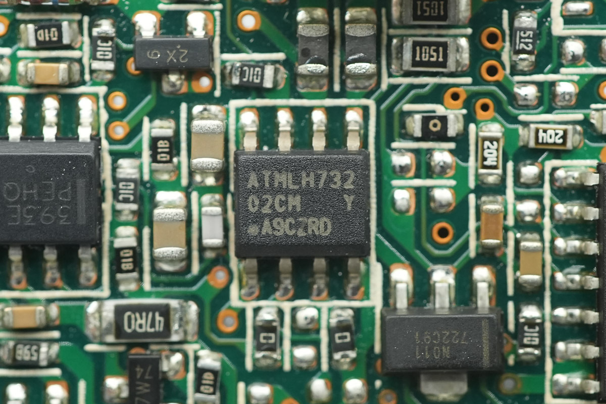
The memory is from Microchip, marked 02CM, model AT24C02C, featuring a capacity of 256 bytes, supporting a 1.7-3.6V operating voltage, and utilizing an 8-lead SOIC package.

The operational amplifier is from TI, model TLC27L9C, which is a precision quad single-supply micropower operational amplifier utilizing a SOIC-14 package.
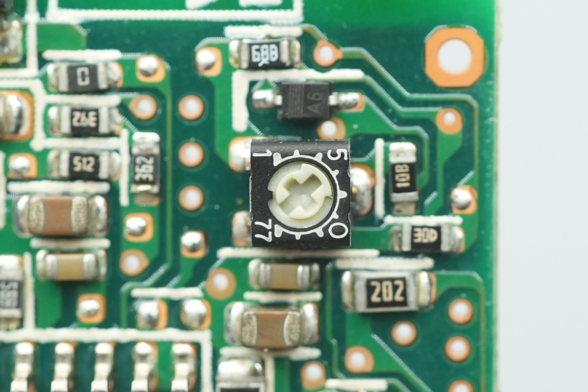
This is the black potentiometer.
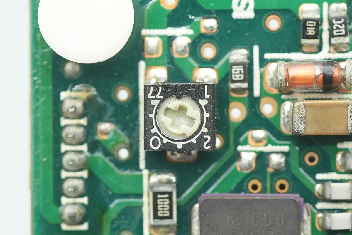
This is the other one.
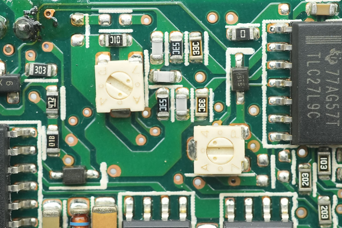
Here are the two white potentiometers.
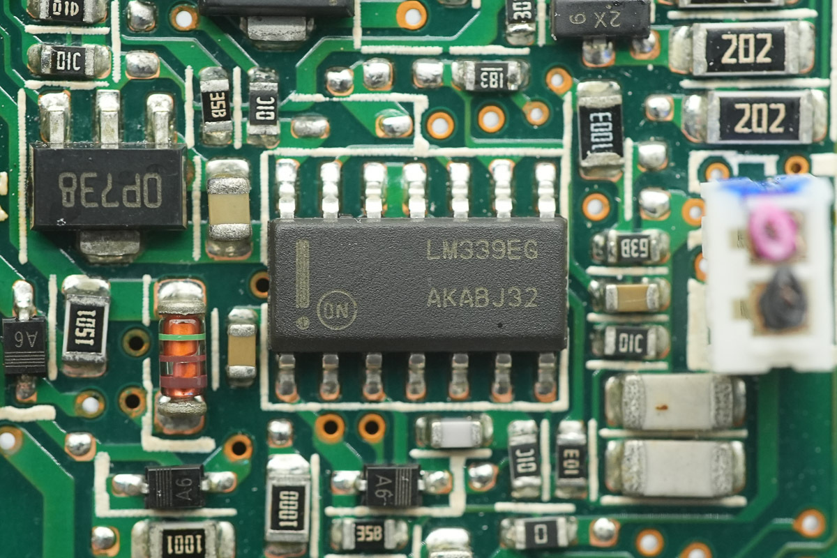
The voltage comparator is from onsemi, model LM339E, which is a single-supply quad voltage comparator utilizing a SOIC-14 package.
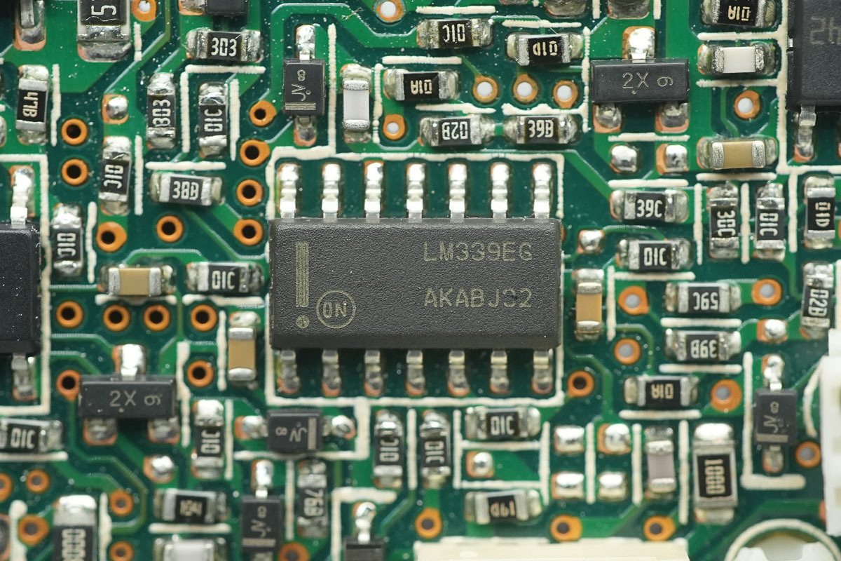
Another oneshares the same model.
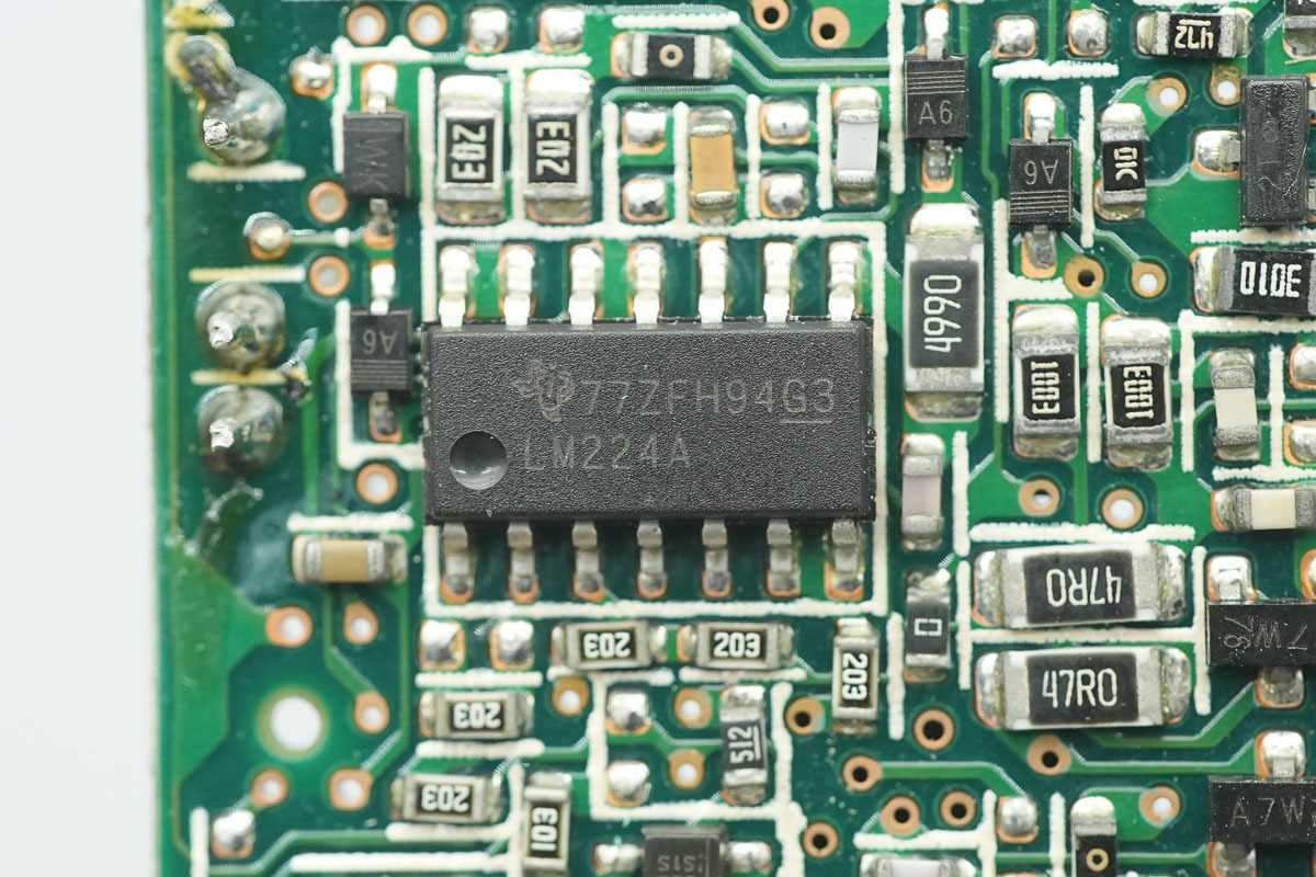
The operational amplifier is from TI, model LM224A, which is a quad operational amplifier utilizing a SOIC-14 package.
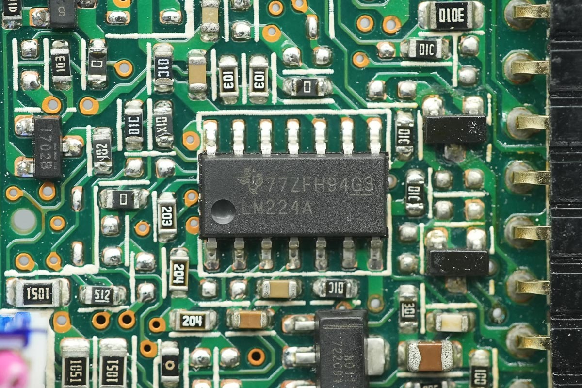
Another one shares the same model.
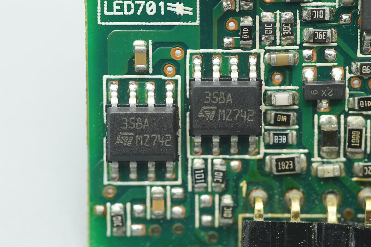
The operational amplifier is from ST, model LM358, which is a low-power dual operational amplifier utilizing an SO-8 package.
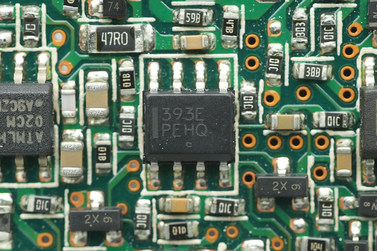
The voltage comparator is from onsemi, model LM393E, which is a dual voltage comparator utilizing an SOIC-8 package.
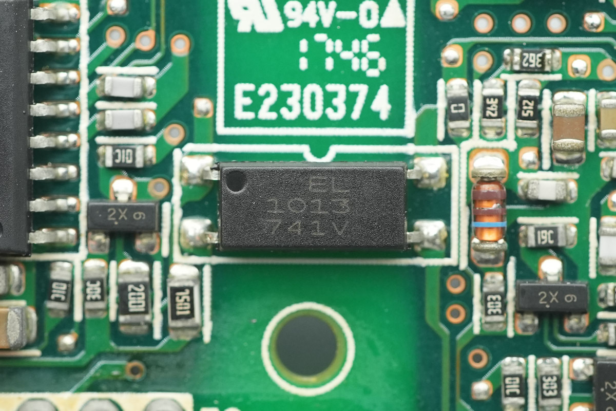
The Everlight EL1013 optocoupler is used for isolated communication.
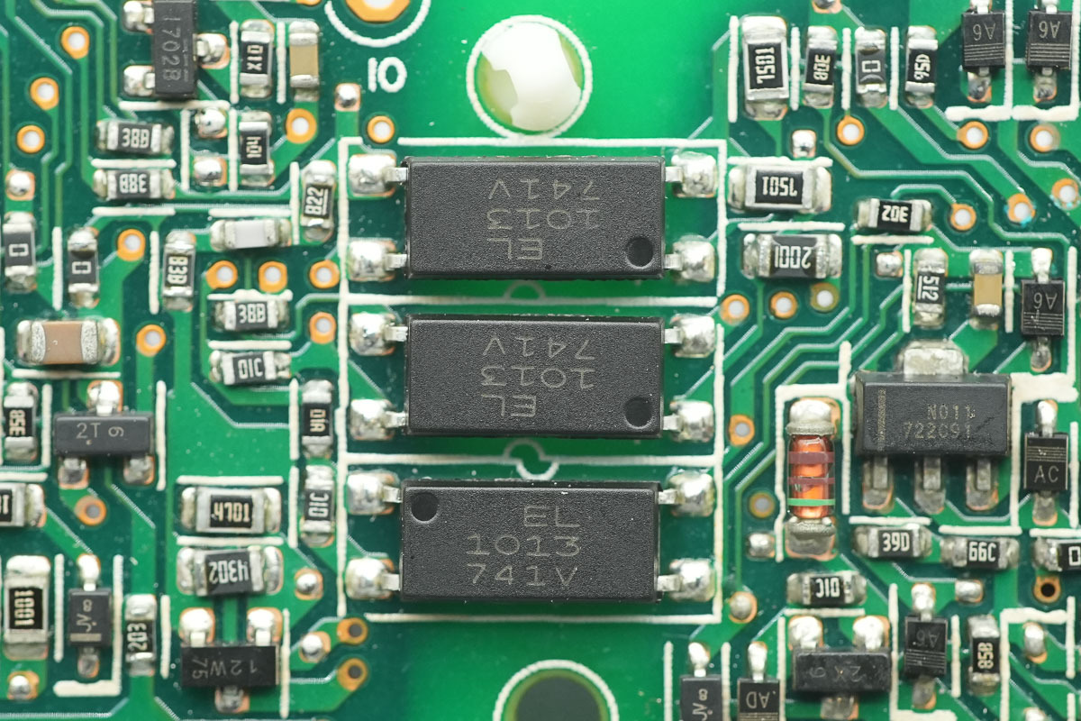
There are three identical optocouplers.

Well, those are all components of the Delta 1100W SiC Power Supply DPS-1100AB-11 A.
Summary of ChargerLAB
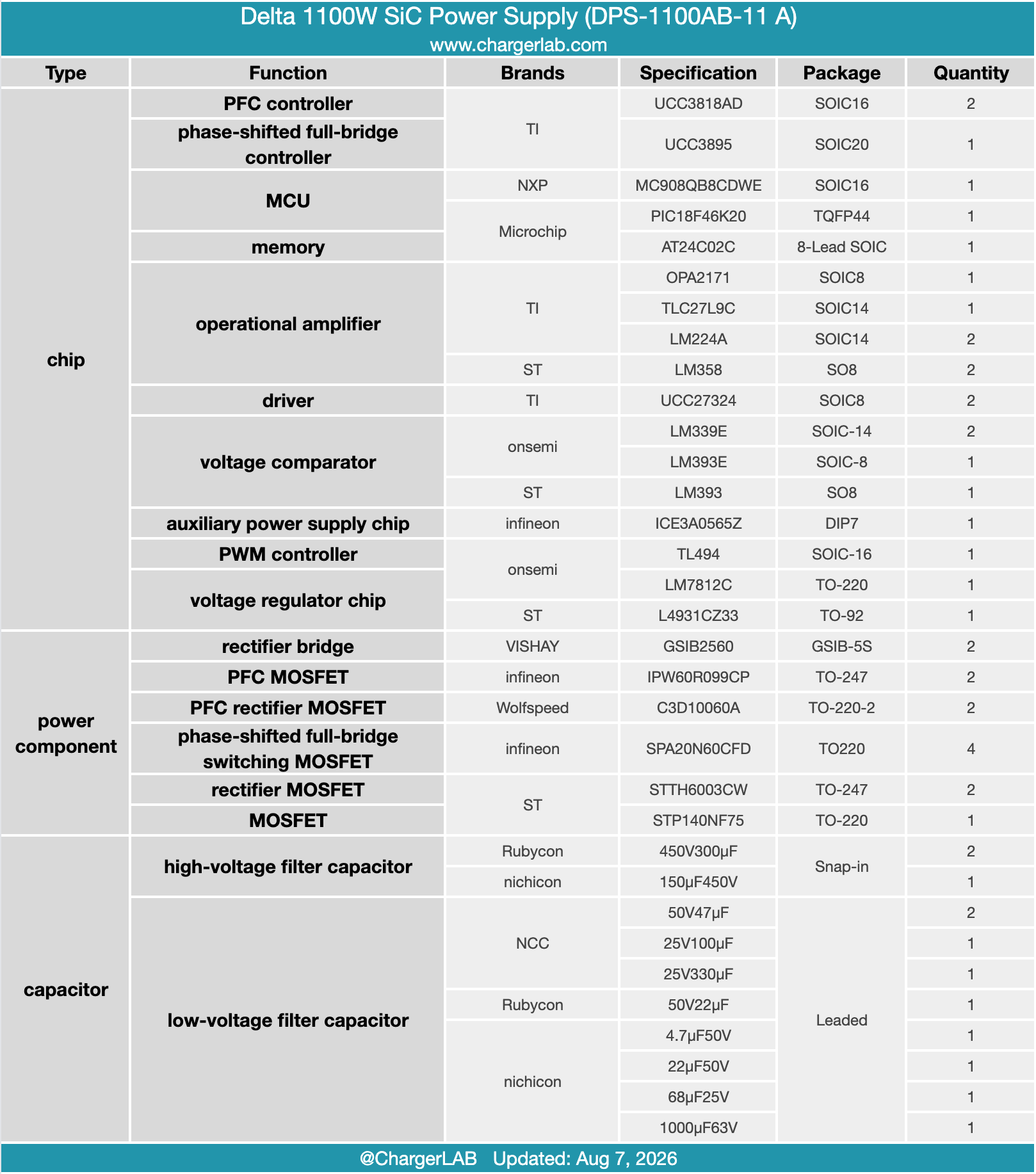
The Delta 1100W SiC Power Supply DPS-1100AB-11 A is engineered for demanding server environments. It supports a wide 115-240V AC input range and delivers a robust -56V output at 19.64A, bringing total maximum output power to an impressive 1100W. For optimal thermal management, a cooling fan is positioned at the output end, drawing fresh air from the input side and exhausting heat smoothly through the rear.
The teardown reveals an advanced topology featuring an interleaved PFC combined with a phase-shifted full-bridge architecture. At the command center are TI controllers—specifically the UCC3818D PFC controller and UCC3895 phase-shifted full-bridge controller. Power handling is top-tier: Infineon IPW60R099CP MOSFETs and Wolfspeed C3D10060A rectifier MOSFETs handle the PFC stage.
Driving the bridge are Infineon SPA20N60CFD MOSFETs, expertly isolated and driven by a TI UCC27324 driver, alongside ST STTH6003CW rectifiers. System intelligence and parameter monitoring are managed by dedicated MCUs from NXP and Microchip, while premium Japanese brand filter capacitors ensure longevity. Generous internal potting and adhesive reinforcement cap off a build quality that is both robust and meticulously engineered.