

Introduction
We are tearing down the Delta 2030W SiC server power supply (Model: DPST-2030AB D). This unit supports 100-120V/200-240V AC inputs alongside 240V DC input, delivering a 12.4V output at 161.3A with 80PLUS Platinum efficiency.
Housed in a long metal chassis, it features external cooling fans and AC inputs, with interior gold-finger connectors for server connectivity. The architecture relies on a PFC + half-bridge LLC + synchronous rectification design. Read on as ChargerLAB explores the internal engineering and component selection of this Delta unit.
Product Appearance
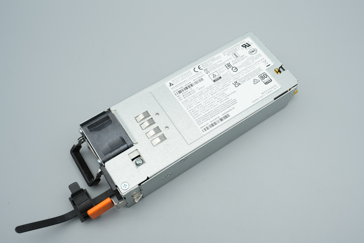
The Delta 2030W SiC server power supply is housed in a durable galvanized steel chassis.
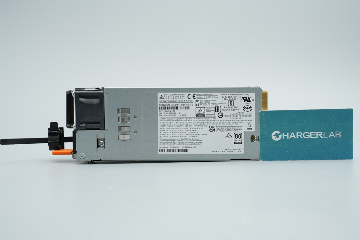
The front features a grounding spring contact and an info label.
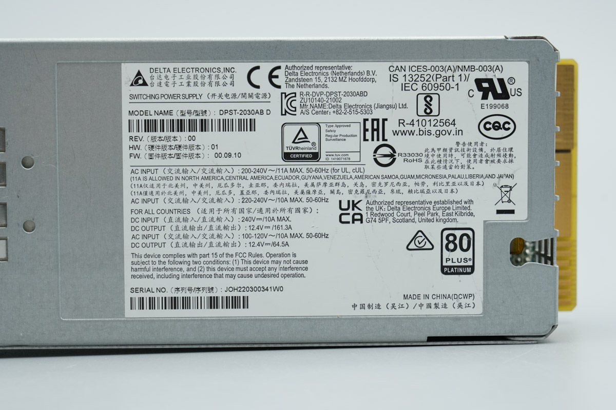
The power supply label:
Model: DPST-2030AB D
AC Input: 200-240V~/11A MAX. 50-60Hz
AC Input: 220-240V~/10A MAX 50-60Hz
DC Input: 240V⎓/10A MAX
DC Output: 12.4V⎓/161.3A
AC Input: 100-120V/10A MAX. 50-60Hz
DC Output: 12.4V⎓/64.5A
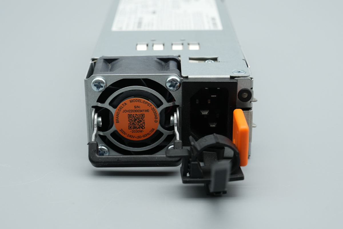
The input end features a cooling fan, an IEC power socket, and an LED indicator.
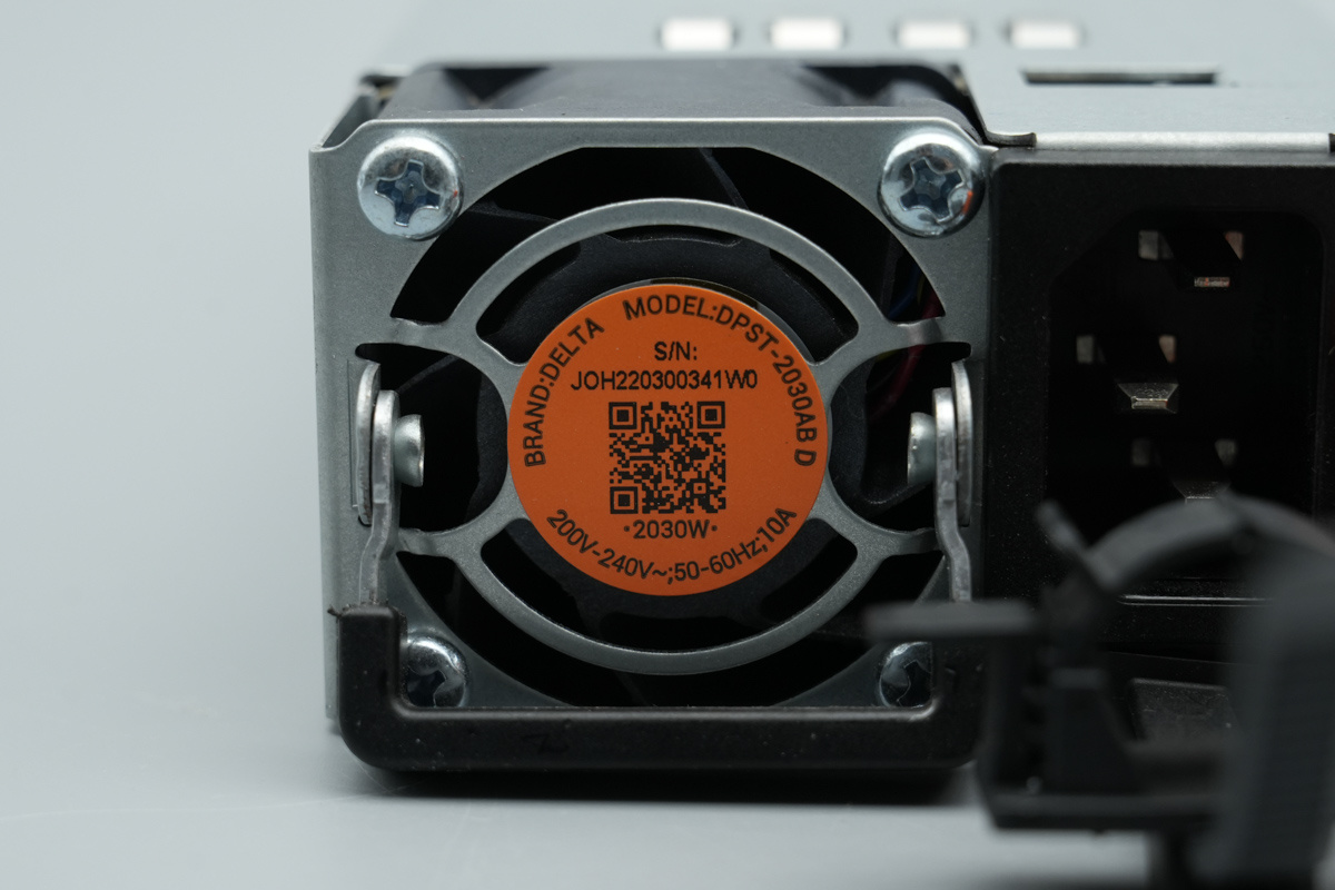
The sticker indicates the power supply brand, model, serial number, and input specs.
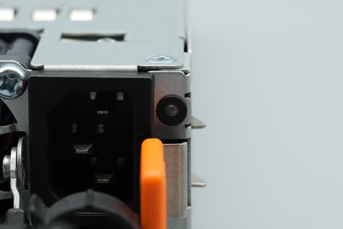
There is the LED indicator.
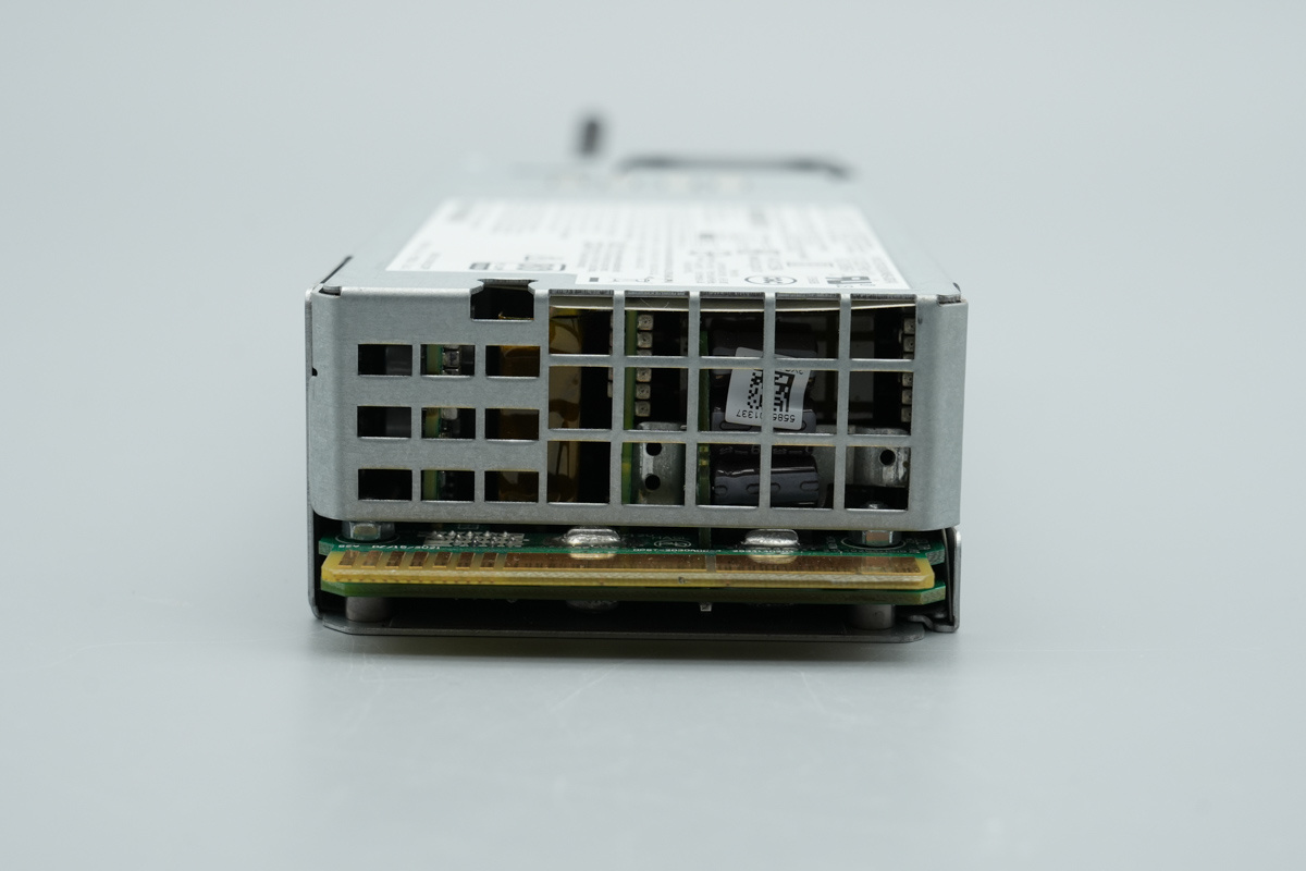
The output end is equipped with cooling grilles and gold fingers.
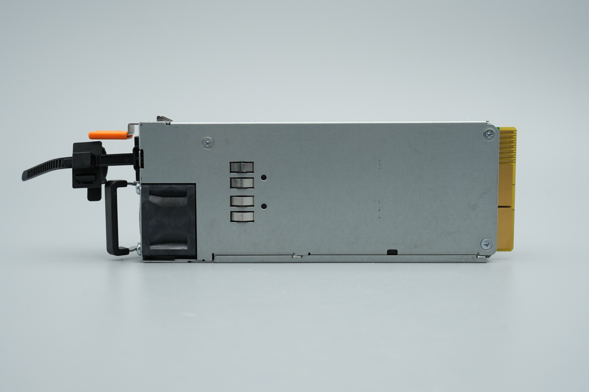
The back of the chassis is equipped with a grounding spring contact.
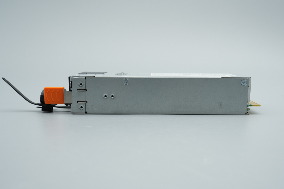
The side is equipped with a locking latch and fixing screws.
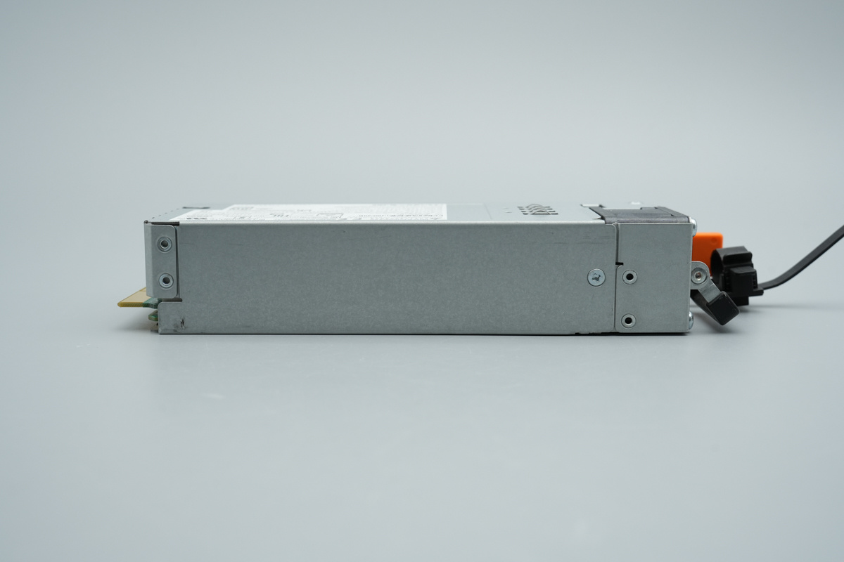
The other side is secured with screws.
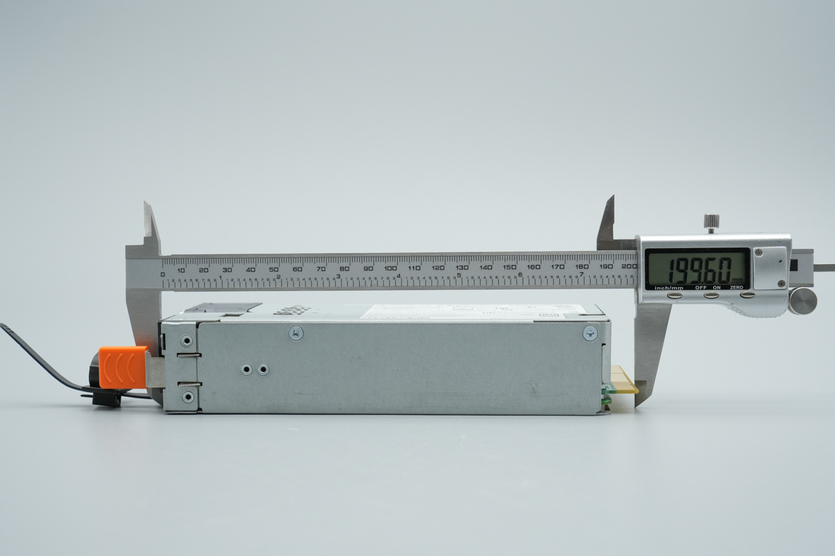
The length of the power supply is about 199.6mm (7.858 inches).
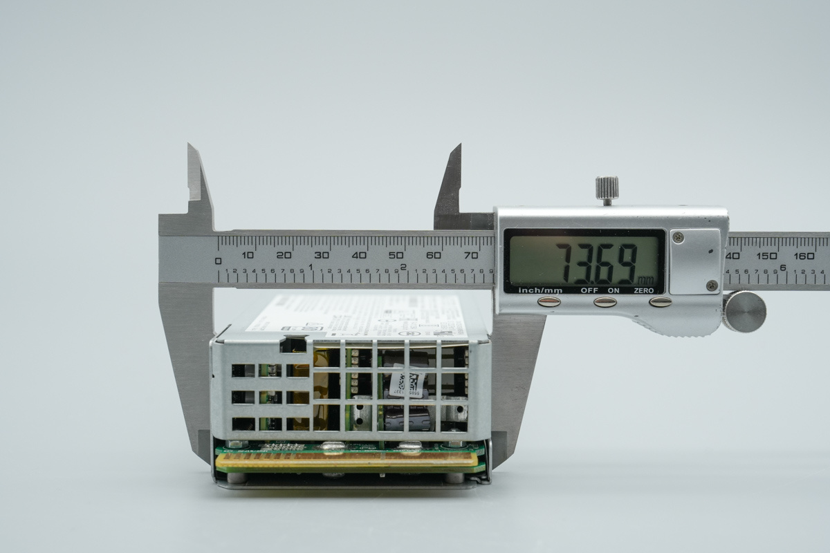
The width of the power supply is about 73.7mm (2.902 inches).
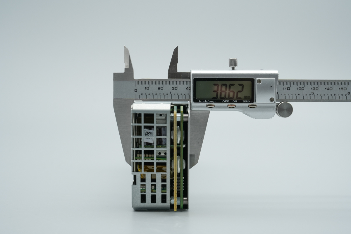
The thickness of the power supply is about 38.6mm (1.520 inches).
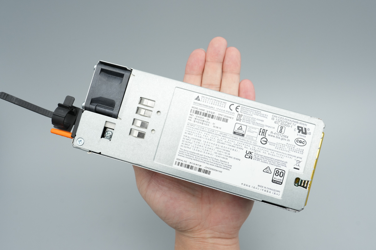
That's how big it is in the hand.
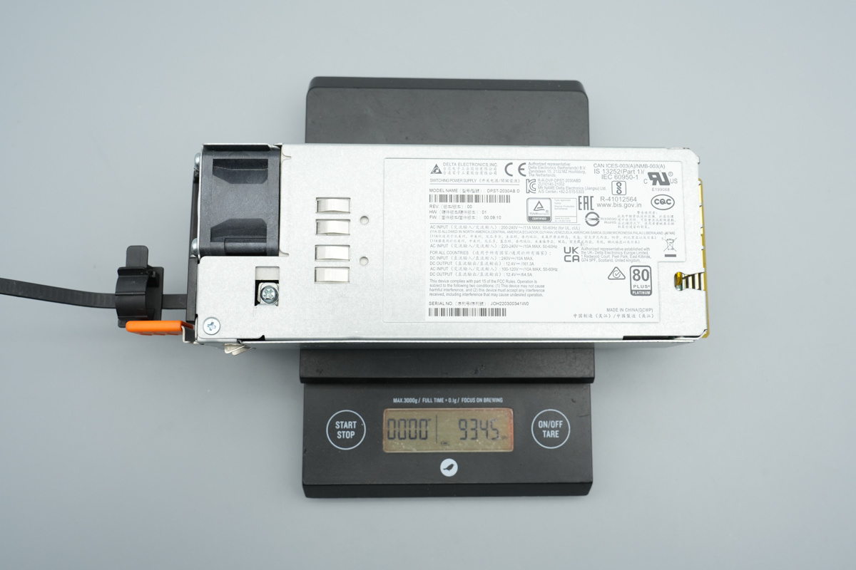
The weight is about 934.5g (32.965 oz).
Teardown
With the exterior overview complete, we now dive into the teardown of Delta server power supply to uncover its internal circuitry and component choices.
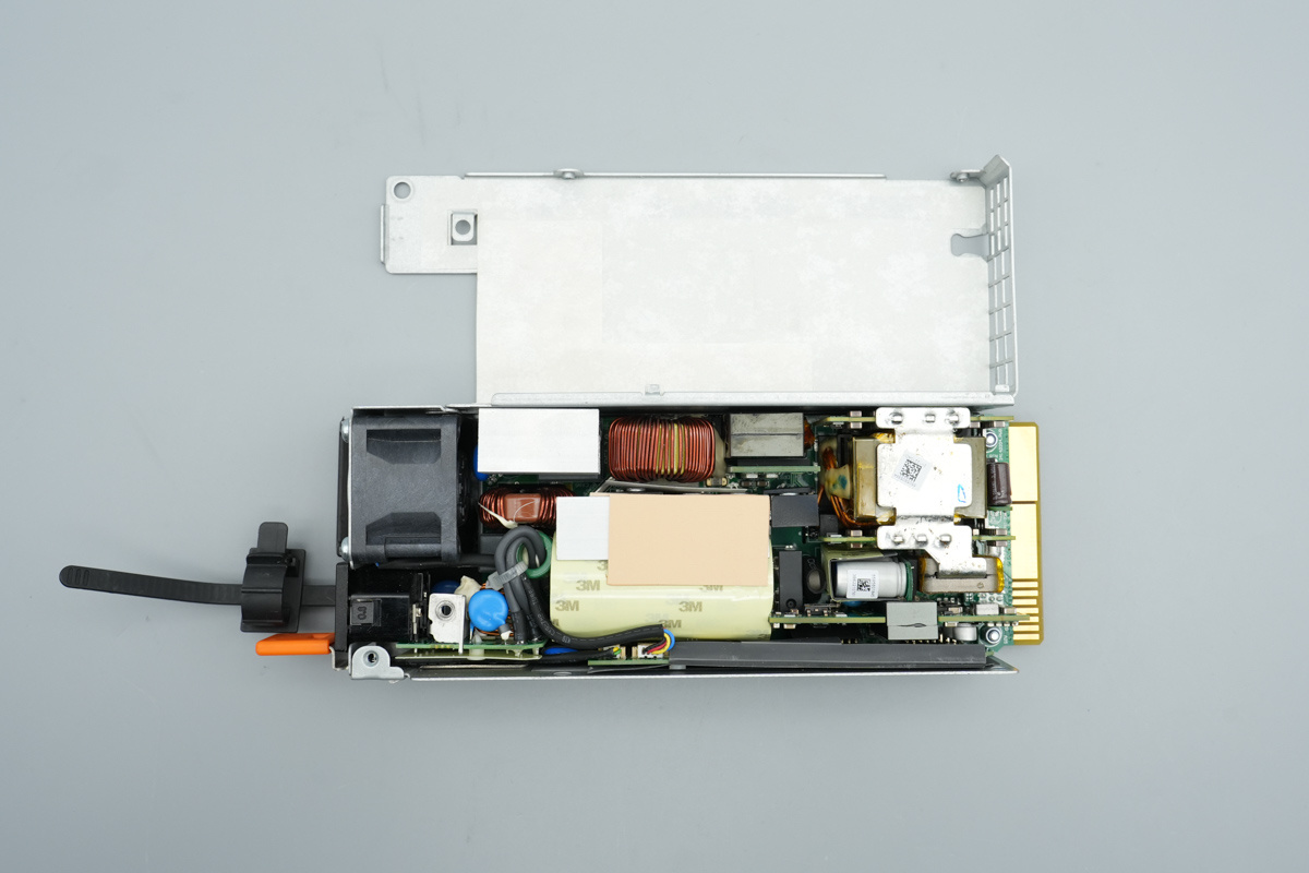
After removing the fixing screws, the metal casing is opened, revealing interior Mylar insulation sheets.
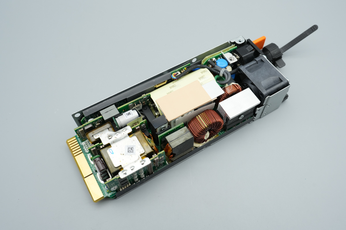
The PCBA module is secured inside the chassis with screws.
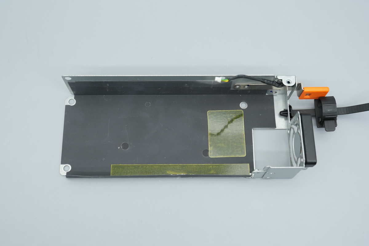
Unscrew the screws, remove the PCBA module, and note that the interior of the casing is lined with Mylar insulation sheets.
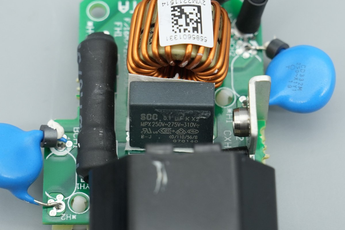
The input end features a PCB soldered with fuses, a safety X2 cap, blue Y-caps, and filtering chokes. The safety X2 cap is from SCC, spec 0.1μF.
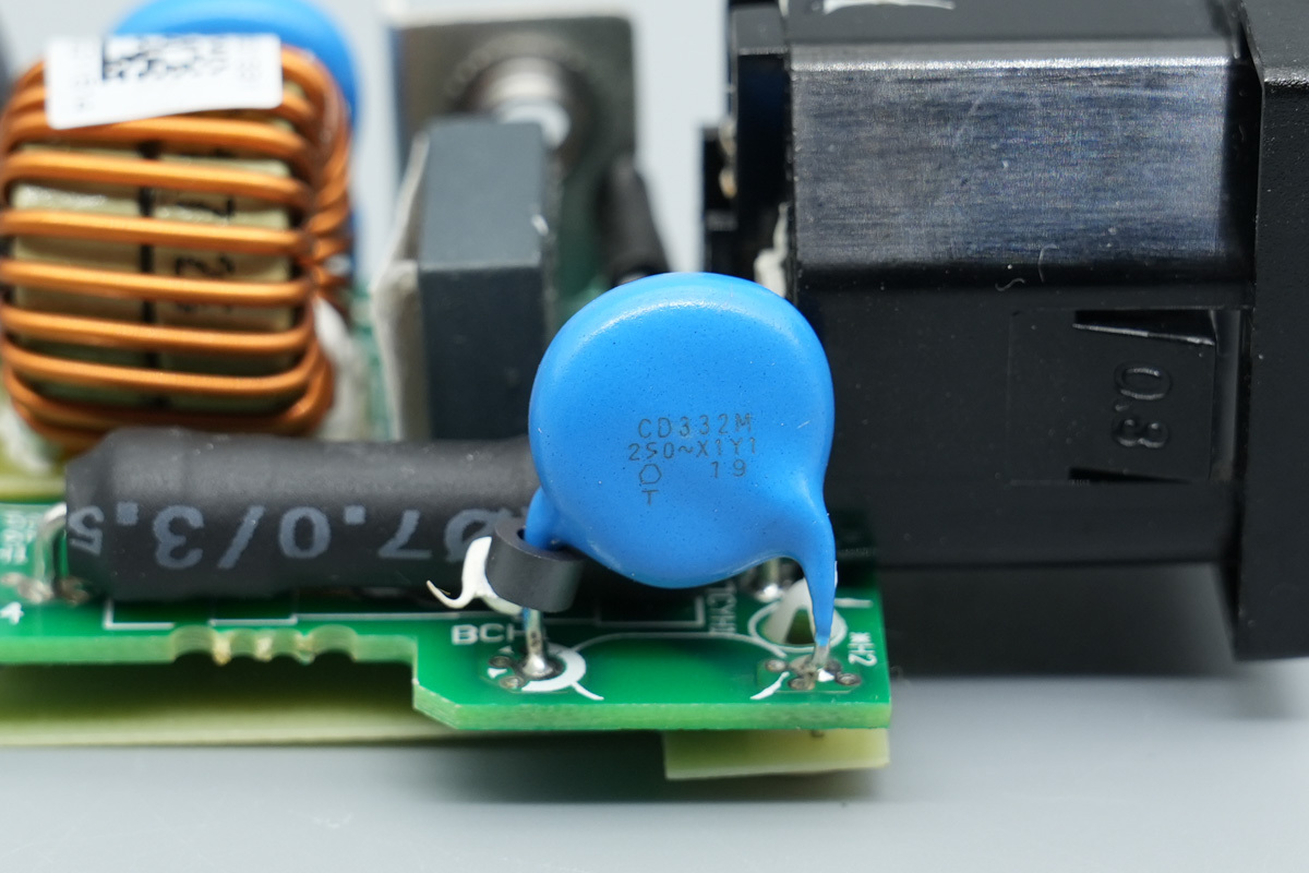
The blue Y-cap is from TDK, model CD332M.
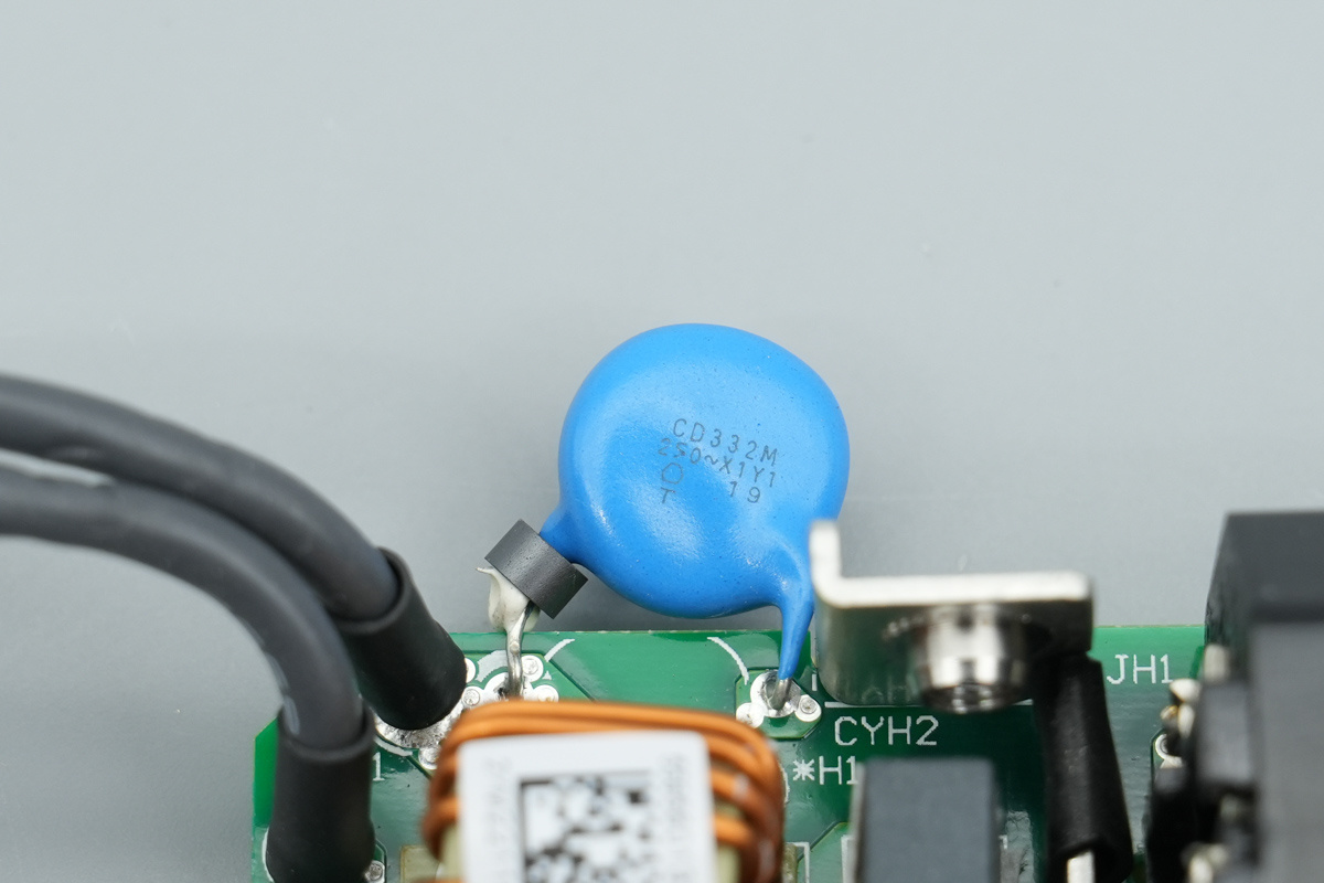
Another one shares the same model.
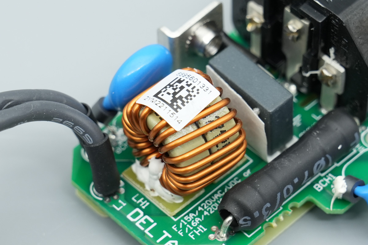
The filtering chokes are wound with enameled wire, with a Bakelite insulation PCB at the bottom.
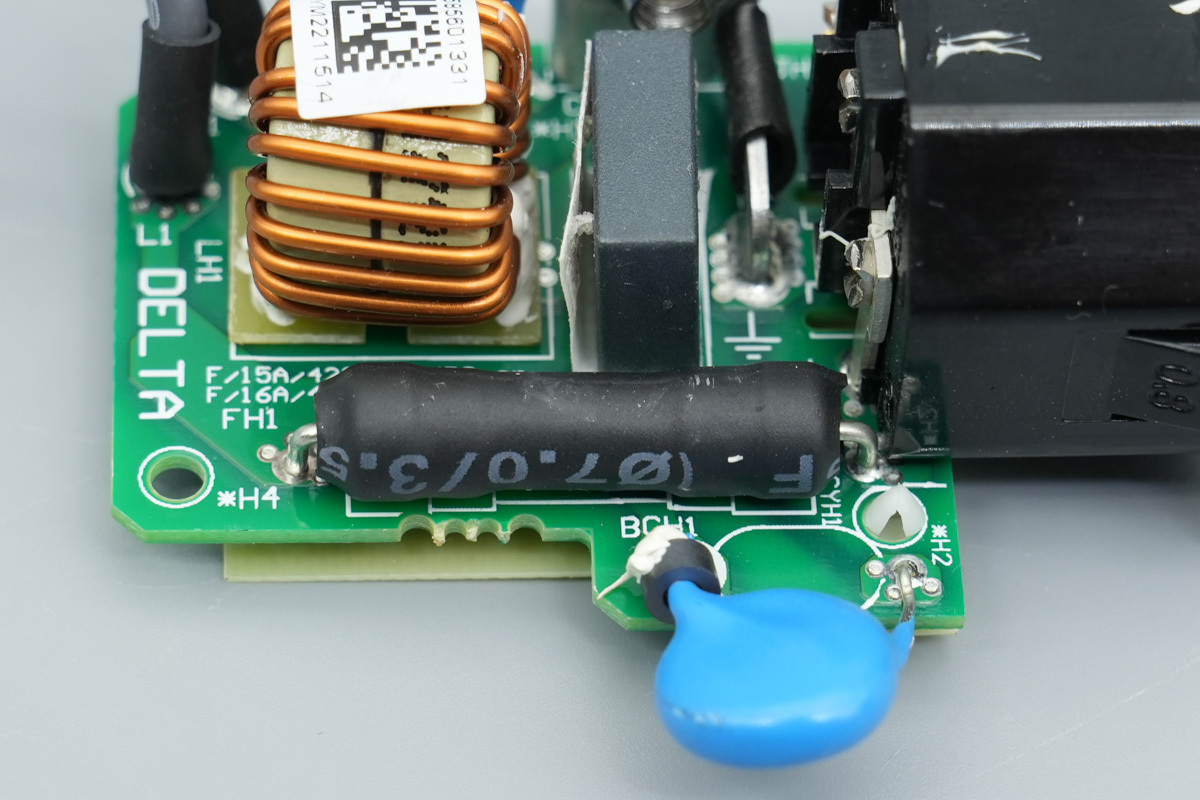
The fuse is insulated with heat-shrink tubing.
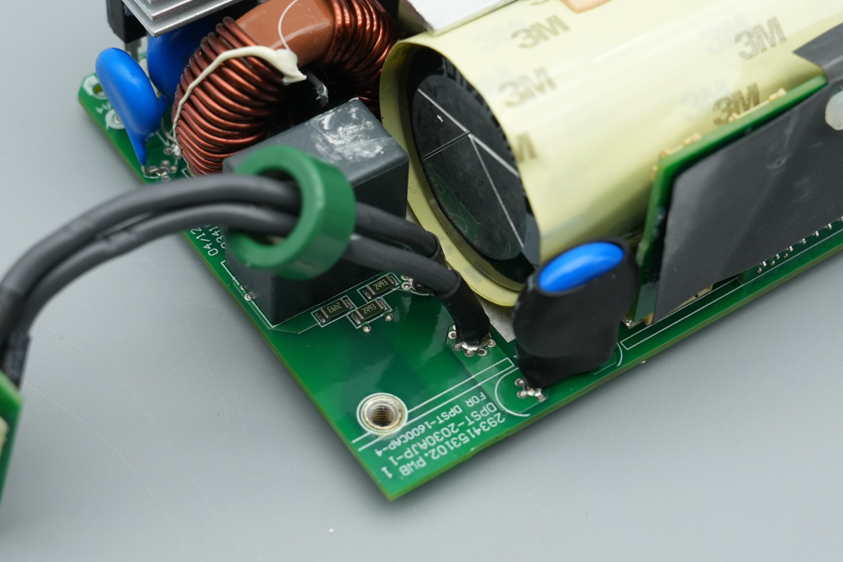
Wires are soldered to connect and supply power to the PCBA module.
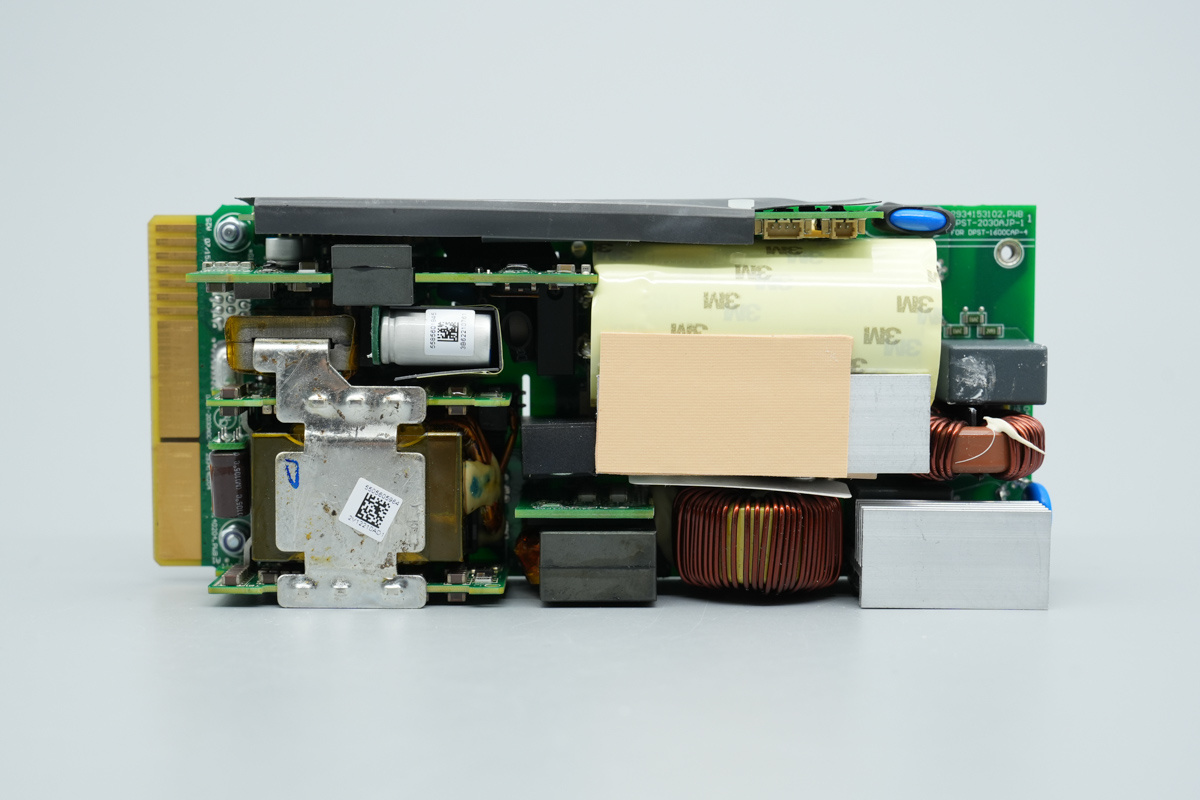
The top of the PCBA module: The right is the AC input end, featuring varistors, a safety X2 cap, common-mode chokes, and rectifier bridges. Moving to the left, it is equipped with high-voltage filter caps, PFC and LLC MOSFETs, and the PFC boost choke. The center area features a PCB for the resonant caps and resonant chokes. The high-voltage filter caps are wrapped with insulating tape.
The upper section houses the control PCB; the upper-left features the auxiliary power PCB; and the lower-left section is equipped with filtering chokes, filtering caps, and the LLC transformer. Synchronous rectifier PCBs are located on both sides of the transformer, with soldered copper plates for enhanced current-carrying capacity.
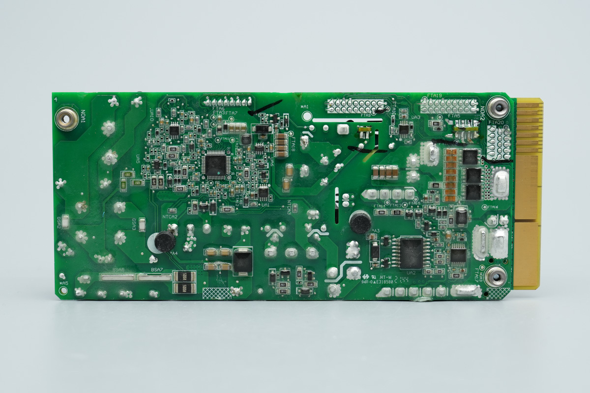
The back features the PFC controller, voltage comparators, gate drivers, isolated drivers, ideal diode controllers, and output control MOSFETs.
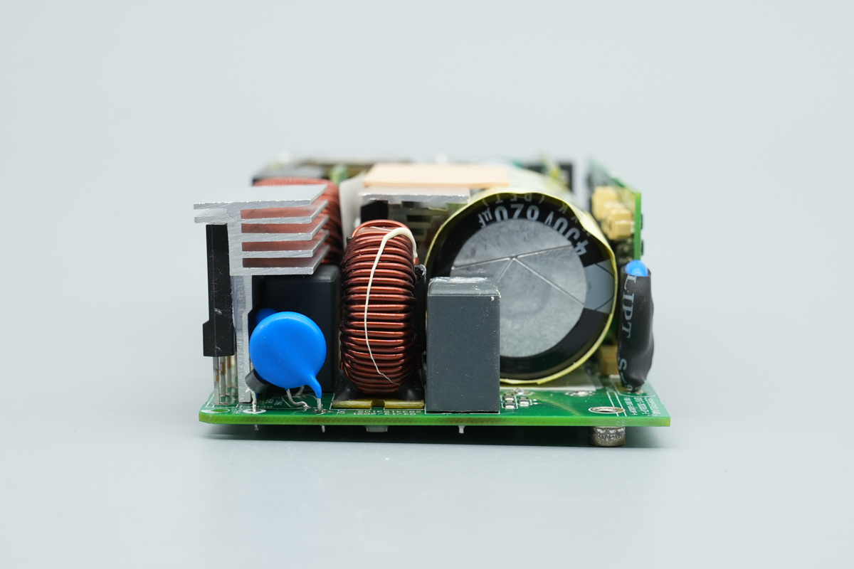
The input end is equipped with varistors, a safety X2 cap, common-mode chokes, and blue Y-caps.
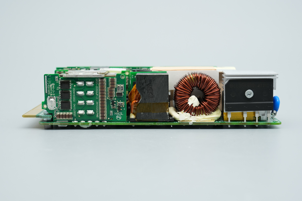
The side features a synchronous rectifier PCB, resonant chokes, PFC boost choke, and rectifier bridges.
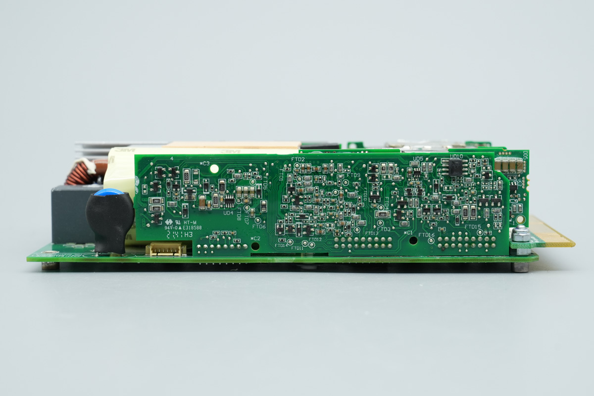
The other side features varistors and the control PCB.
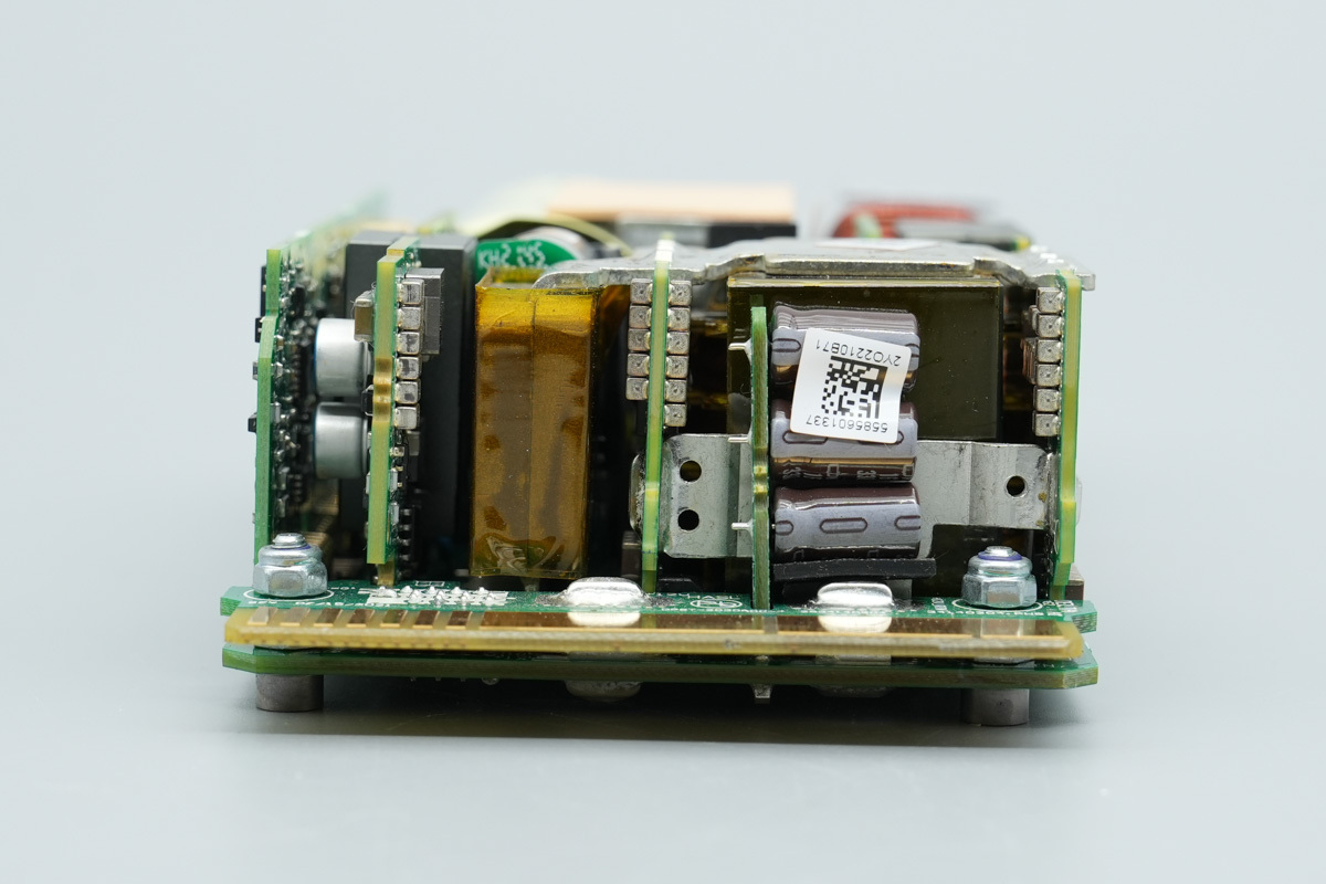
The output end is equipped with the auxiliary power PCB, synchronous rectifier PCB, and the filtering cap PCB.
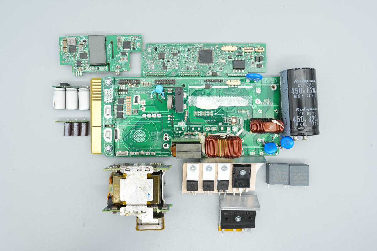
Desolder and remove the transformer, filtering cap PCB, auxiliary PCB, control PCB, high-voltage filter caps, MOSFET heatsink, and rectifier bridge heatsink to continue the teardown.
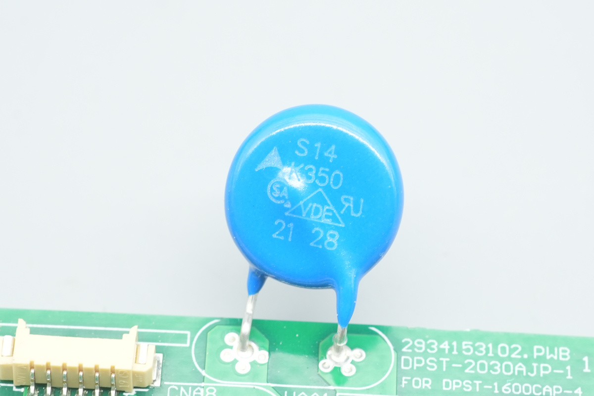
The varistor is from TDK, model S14K350, used for absorbing overvoltage surges.
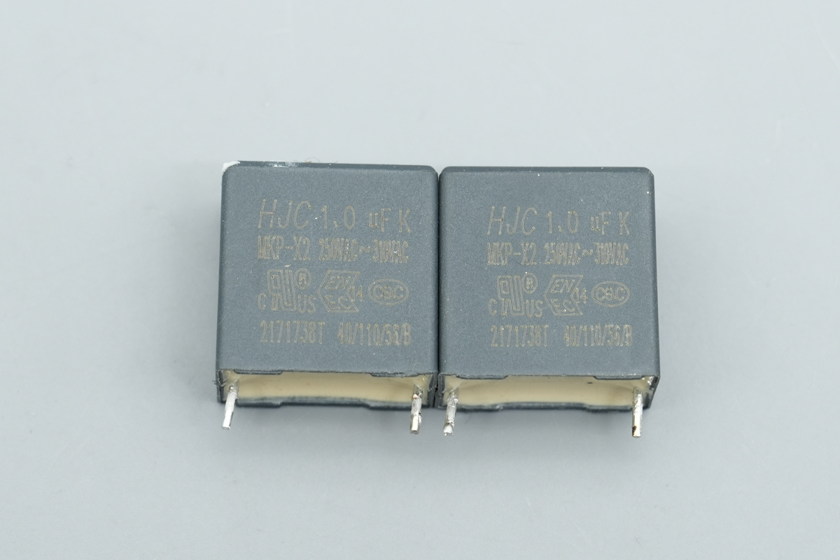
The safety X2 cap is from HJC, spec 1μF.
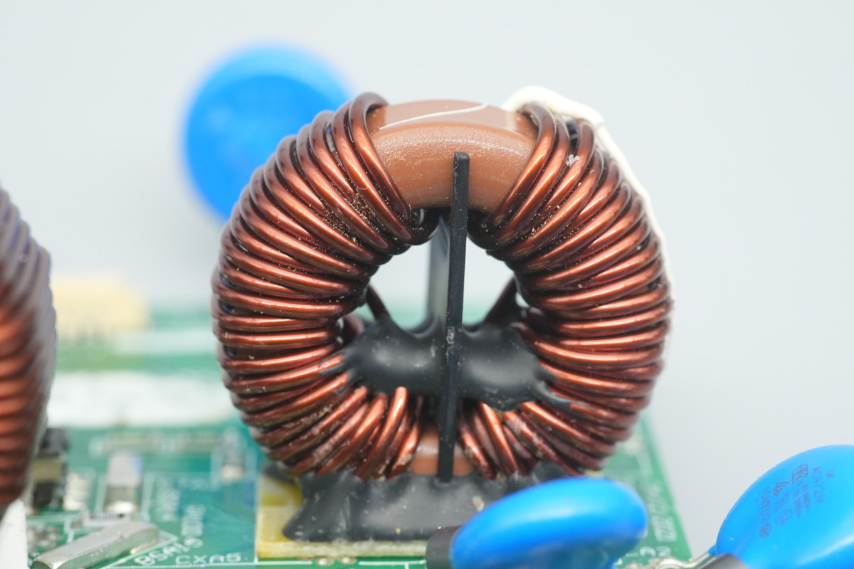
The common-mode choke is wound with enameled wire, featuring internal plastic plate insulation and a bottom Bakelite insulation PCB, secured with potting compound.
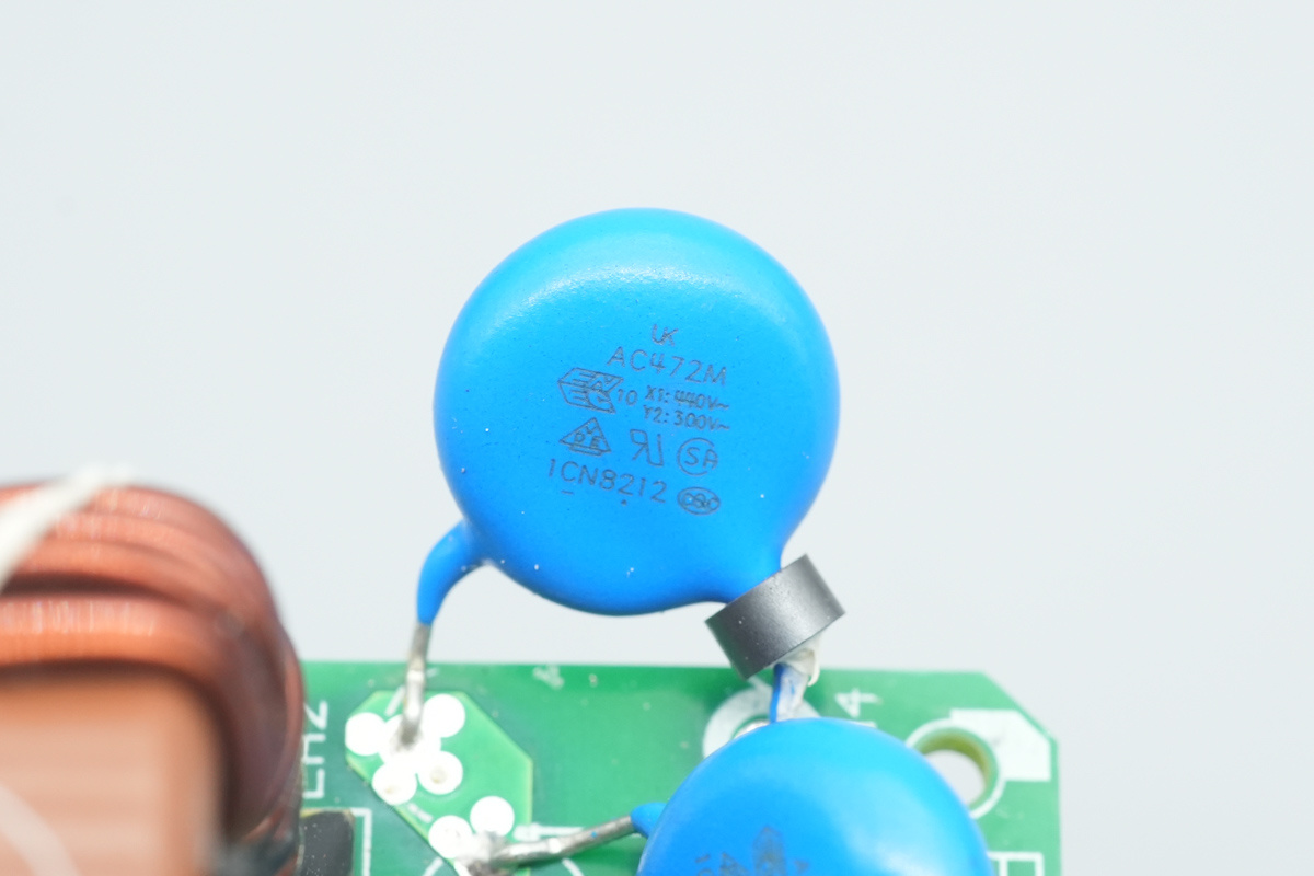
The blue Y-cap is from WTC, spec AC472M.
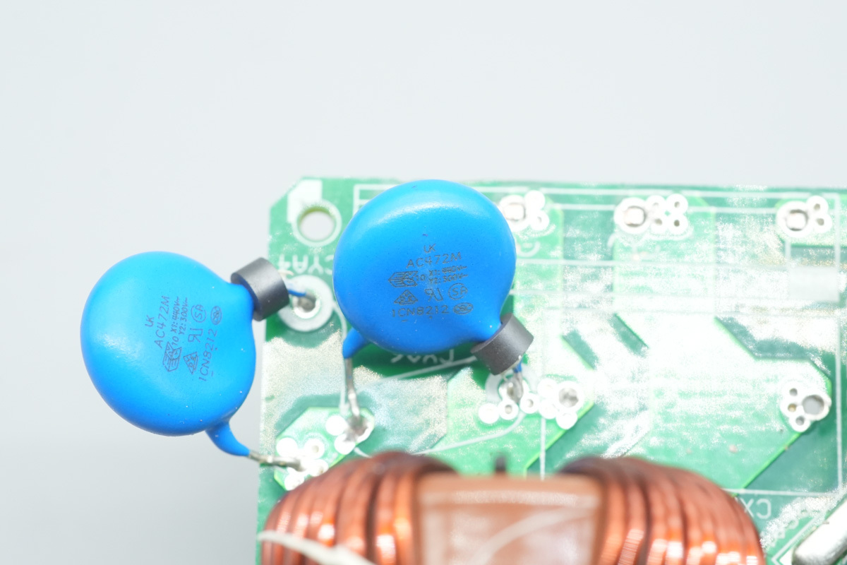
Another one shares the same model.
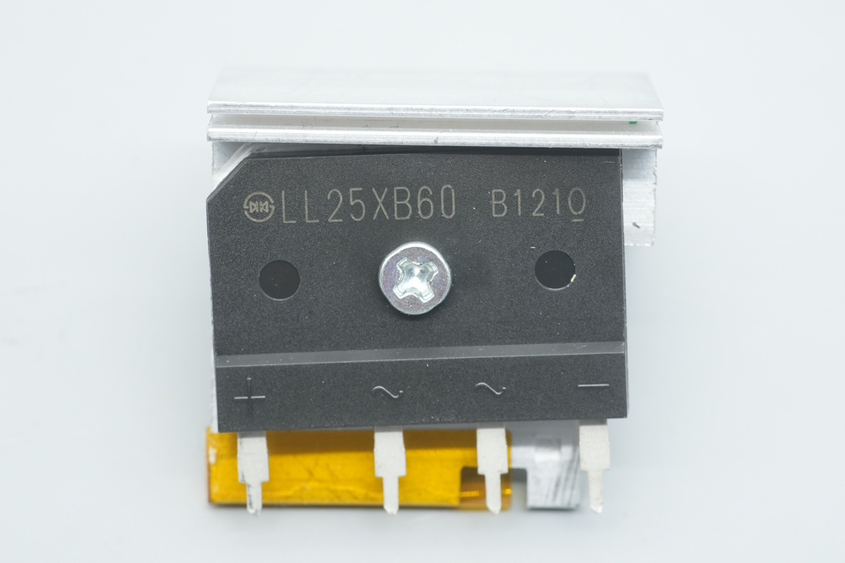
The rectifier bridge is from SHINDENGEN, model LL25XB60, spec 600V 25A, adopting a 5S package.
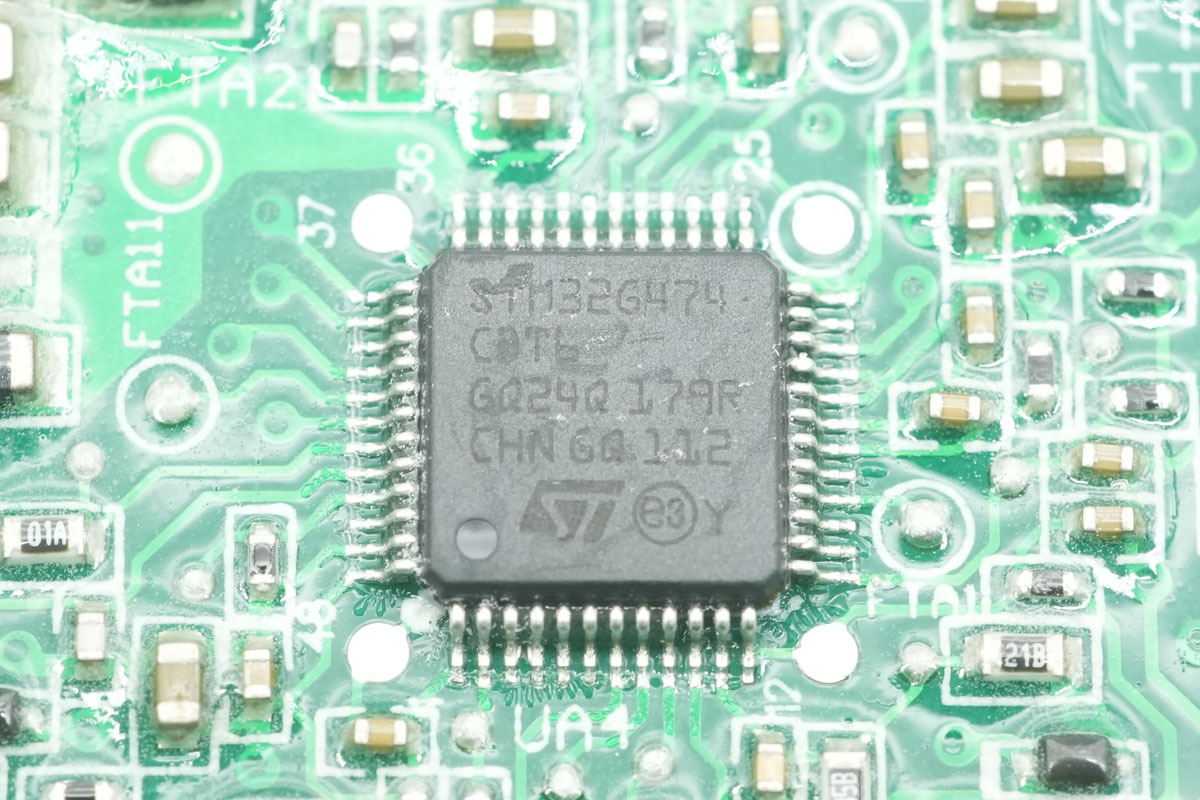
The PFC controller is from ST, model STM32G474CBT6, featuring a built-in ARM Cortex-M4 MCU with a main frequency of 170MHz, integrated FPU and DSP, 128KB Flash memory, and 128KB SRAM. It offers standard and advanced communication interfaces, adopting an LQFP48 package.
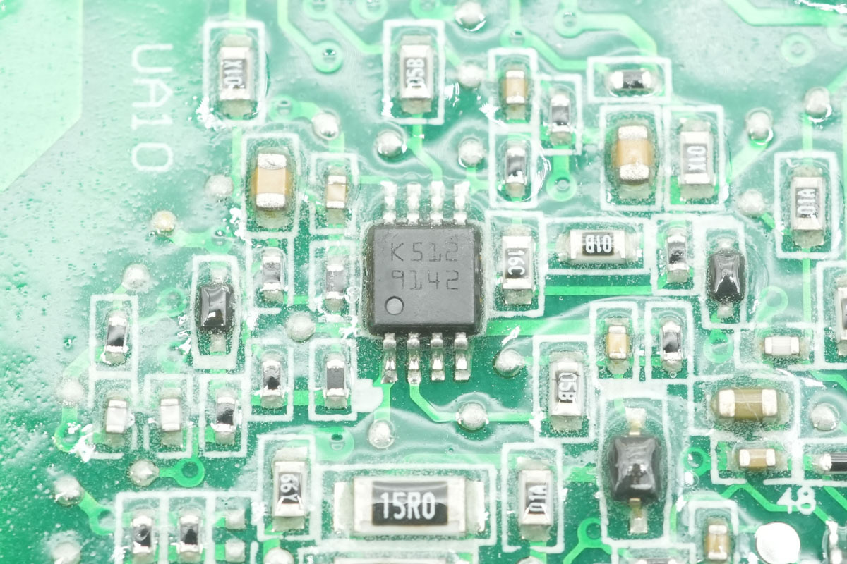
The voltage comparator is from ST, marked K512, model LM293ST, a low-power dual voltage comparator adopting a Mini-SO8 package.
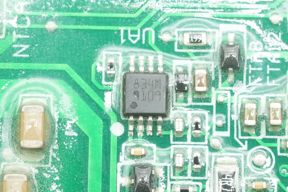
The gate driver is from ST, model PM8834, a dual low-side driver featuring a 4A output capability, adopting an MSOP8L-EP package.
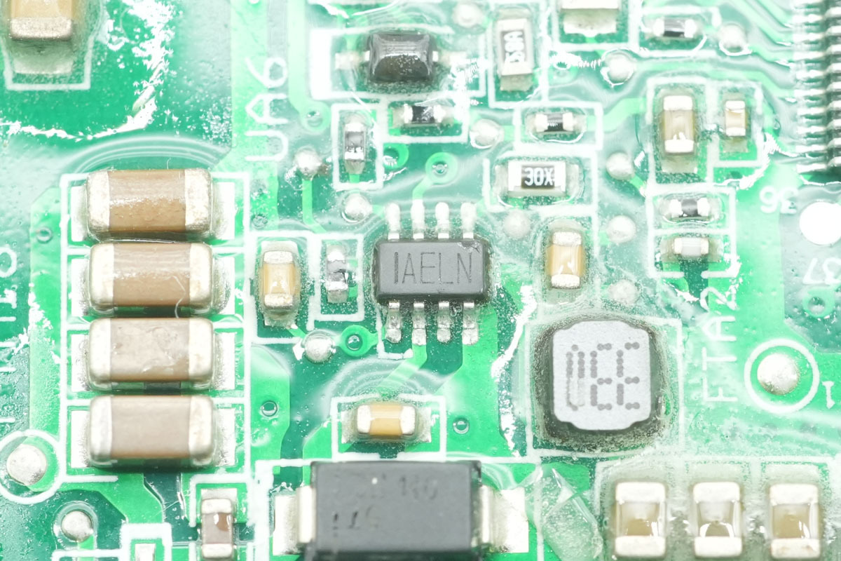
The synchronous step-down chip is from MPS, marked AEL, model MP2314, supporting an input voltage of 4.5V to 24V with a 2A output current. It integrates MOSFETs and operates at a switching frequency of 500kHz, adopting a TSOT23-8 package.
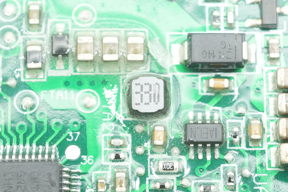
The 33μH step-down choke.
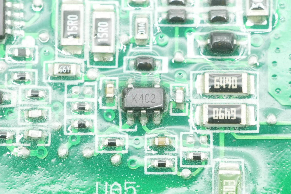
The operational amplifier is from ST, marked K402, model TS321AILT, a low-power single operational amplifier adopting a SOT23-5 package.
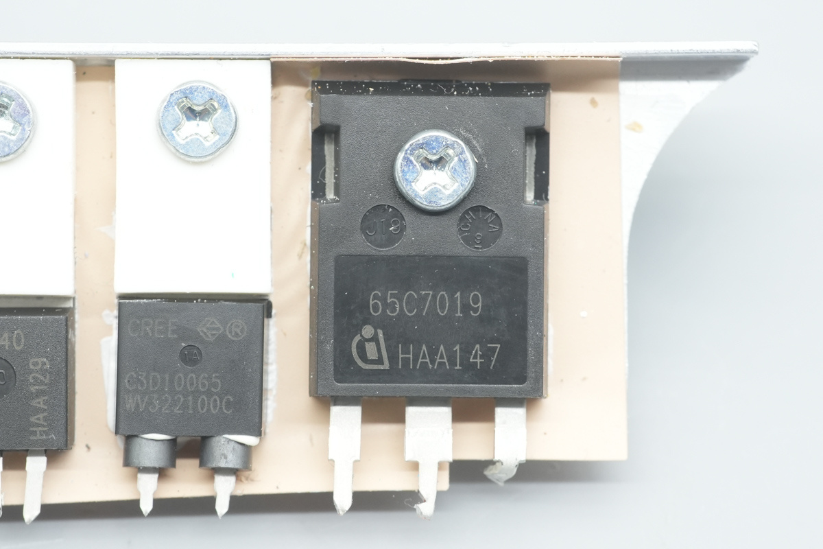
The PFC MOSFET is from Infineon, marked 65C7019, model IPW65R019C7, NMOS, 700V and 9mΩ, adopting a TO-247 package.
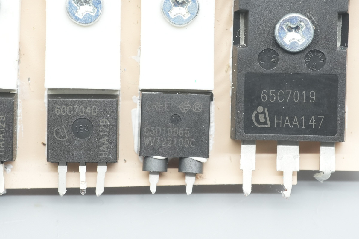
The PFC rectifier MOSFET is from Wolfspeed, model C3D10065A, a SiC Schottky diode with a spec of 650V 10A, adopting a TO-220-2 package.
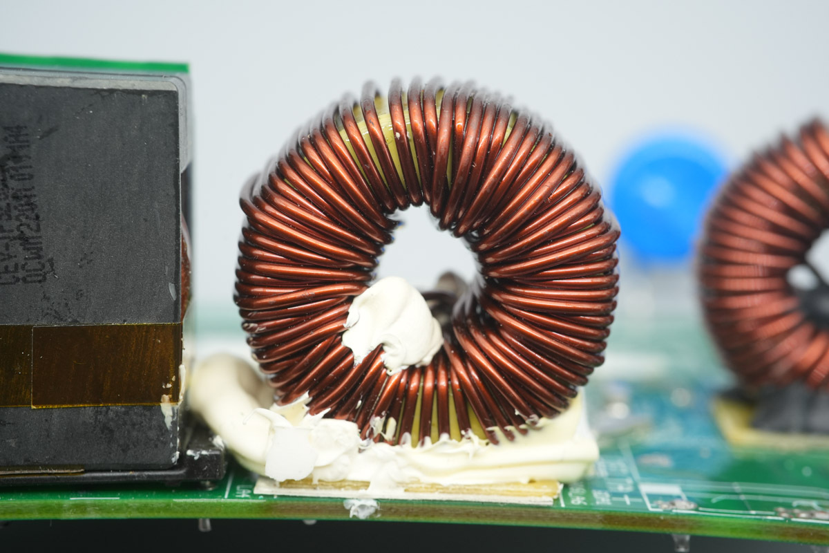
The PFC boost choke is wound with enameled wire, with a Bakelite insulation PCB at the bottom.
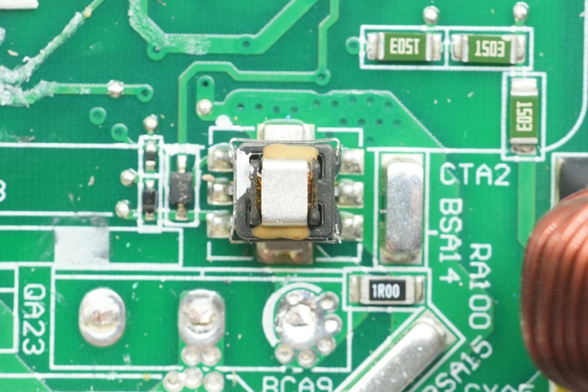
An SMD current transformer is used to detect the PFC MOSFET current.
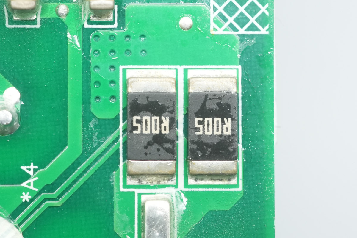
Two 5mΩ current sense resistors are used for input current detection.
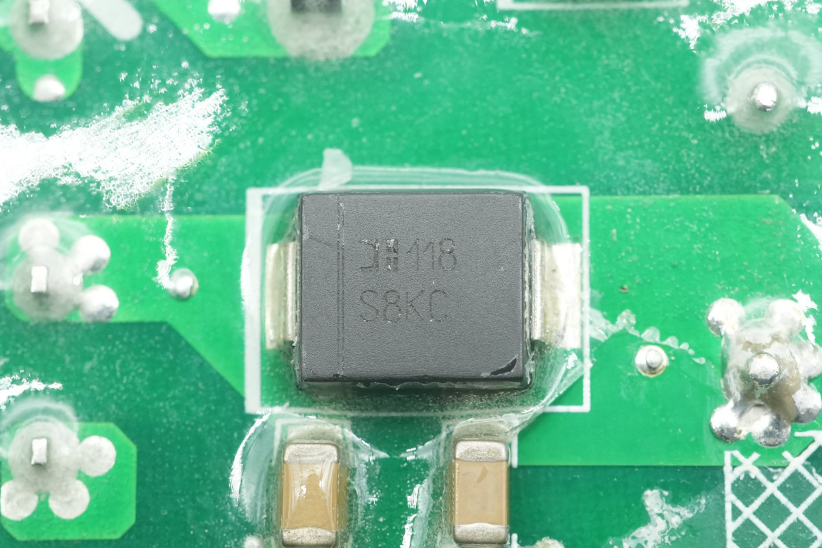
The bypass diode is from DIODES, model S8KC, spec 800V 8A, adopting an SMC package.
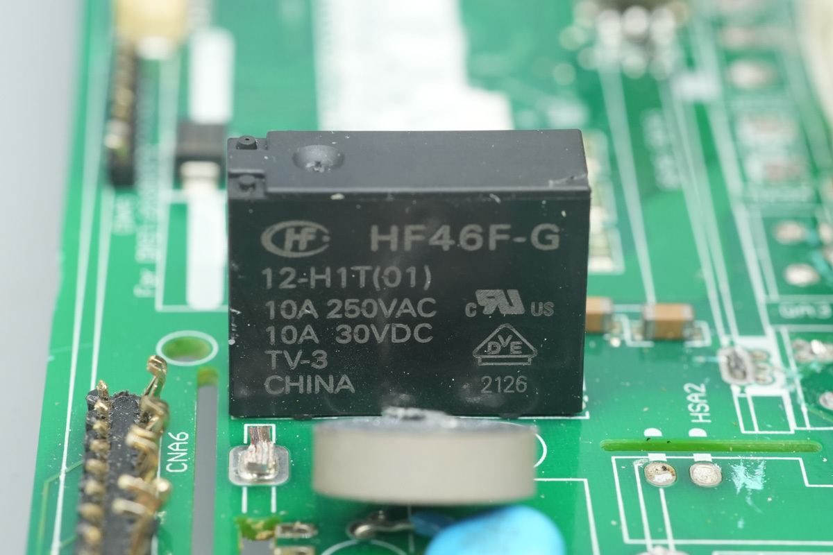
The relay is from HONGFA, model HF46F-G/12-H1T, an ultra-miniature medium-power relay featuring one set of normally open contacts, a 10A contact switching capacity, and a 12V coil voltage.
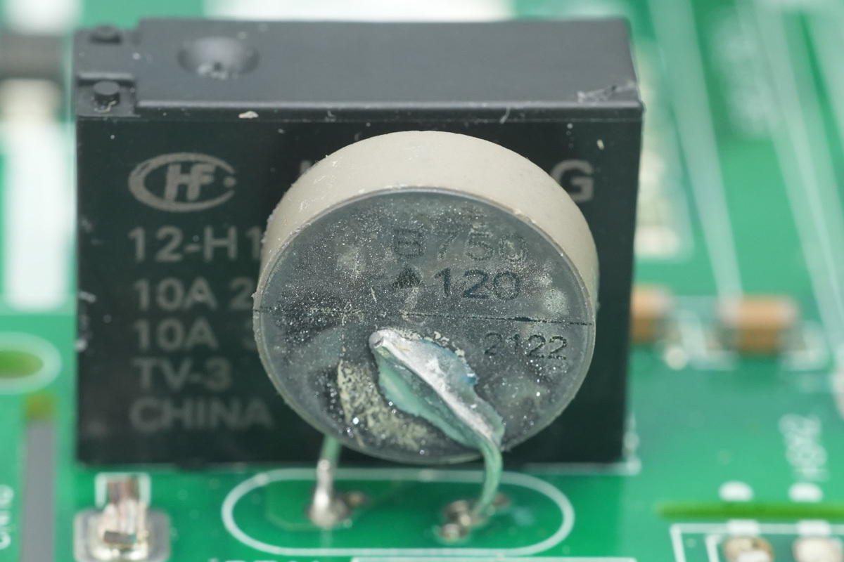
The thermistor connected in parallel with the relay is from TDK, used for suppressing inrush current during cap charging.
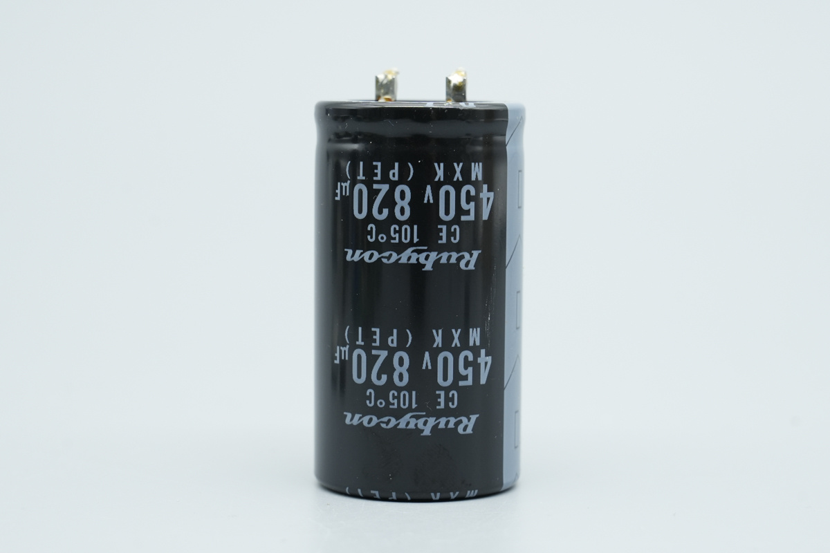
The high-voltage filter cap is from Rubycon, belonging to the MXK series ultra-miniature electrolytic cap, spec 450V820μF.
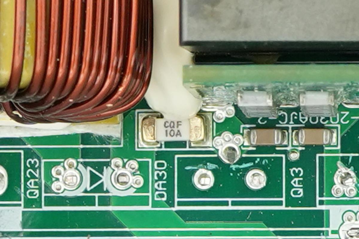
A 10A SMD fuse is used for LLC stage OCP.
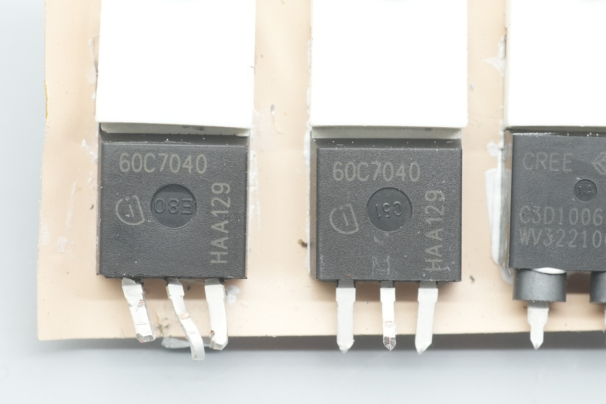
The LLC MOSFET is from Infineon, marked 60C7040, model IPP60R040C7, NMOS, 650V and 40mΩ, adopting a TO-220 package.
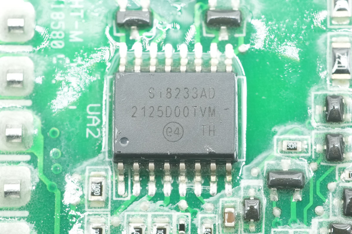
The isolated gate driver is from SKYWORKS, model Si8233AD, a dual isolated driver with a 4A drive capability and support for a 24V supply voltage. It complies with UL1577 certification, providing a 5kVrms galvanic isolation rating, and adopts a SOIC-16WB package.
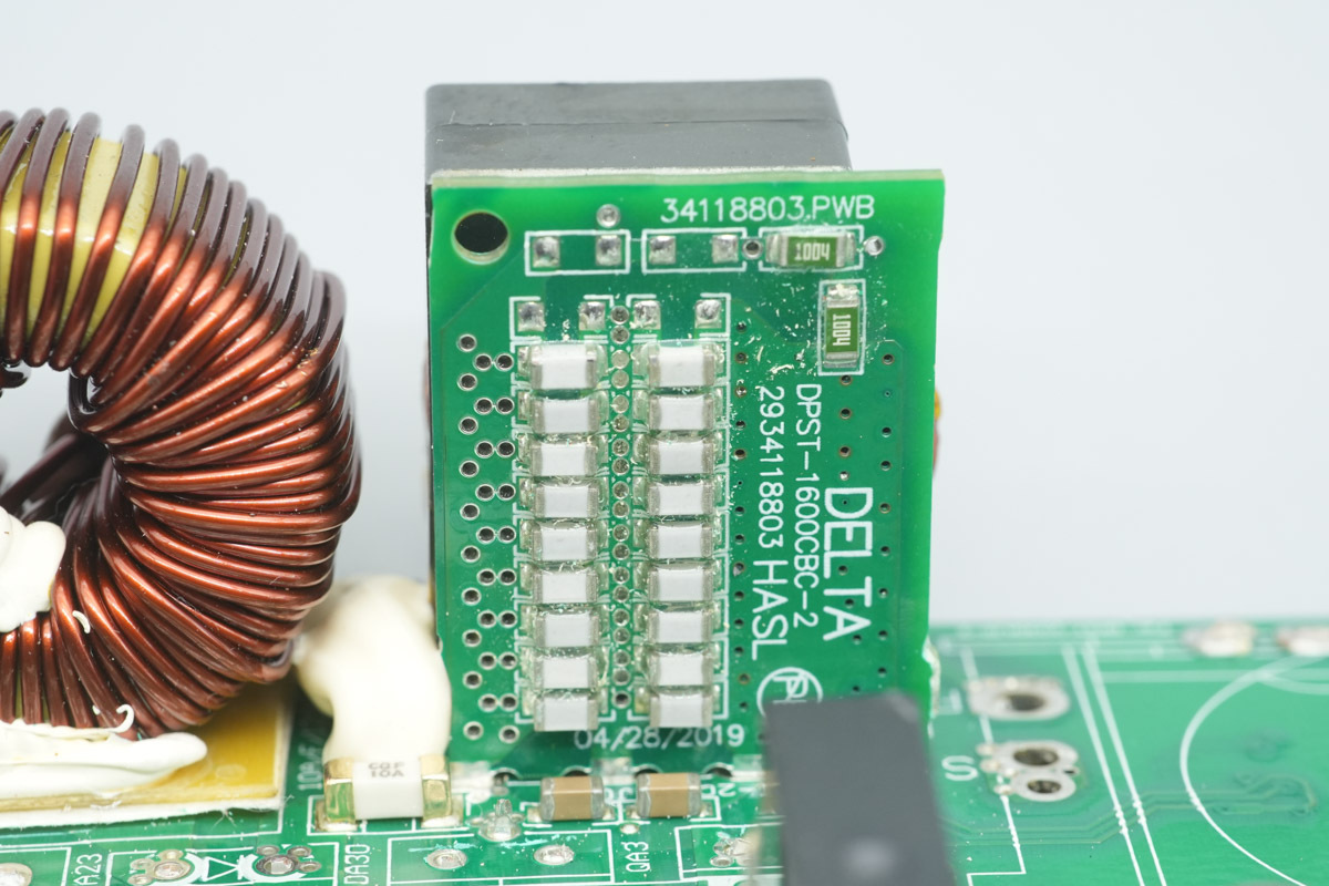
The resonant caps are soldered onto a vertical PCB.
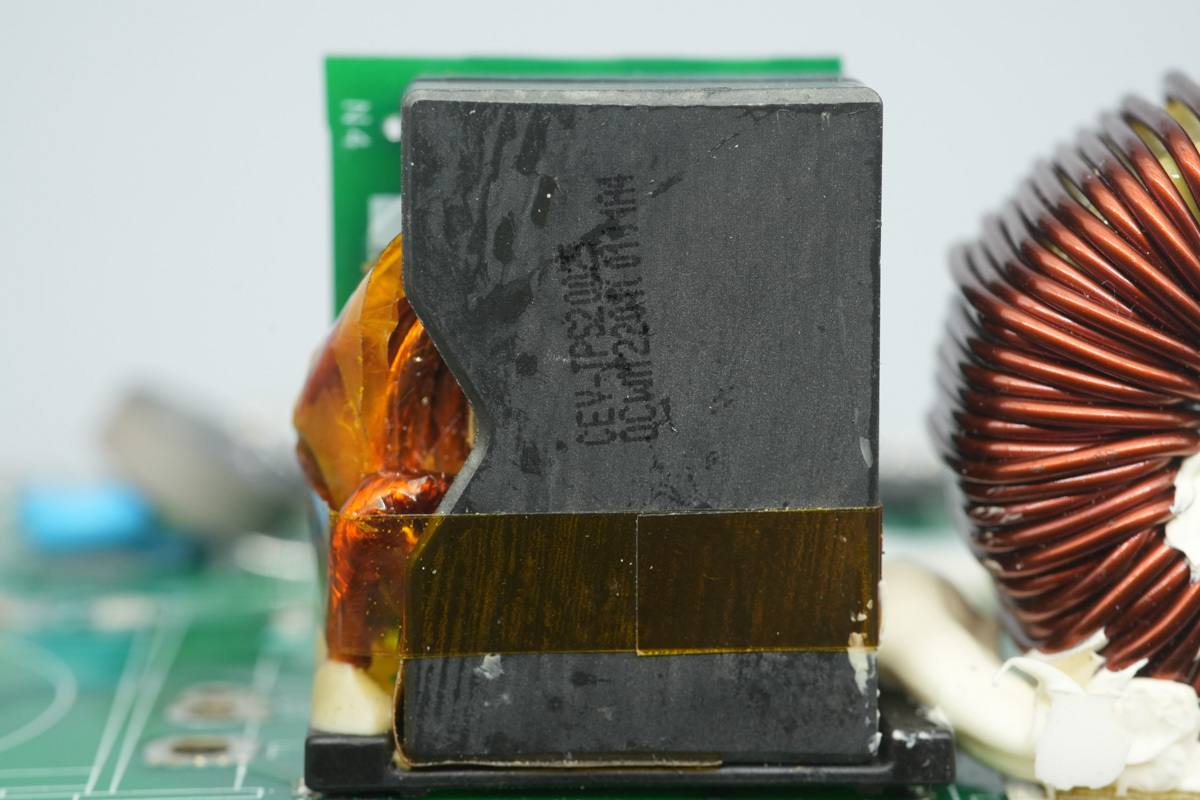
The resonant chokes are wound with litz wire.
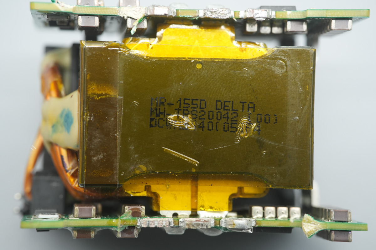
The transformer primary utilizes litz wire coupled with a current transformer, while the secondary employs heavy copper sheet outputs flanked by upper and lower synchronous rectifier PCBs.
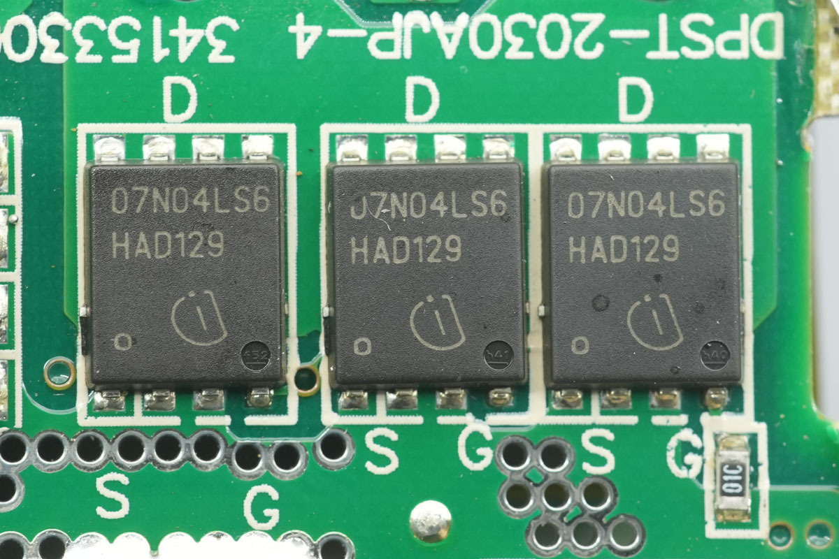
The synchronous rectifier MOSFETs are from Infineon, marked 07N04LS6, model BSC007N04LS6, NMOS, 40V and 0.7mΩ, adopting a TDSON-8FL package.
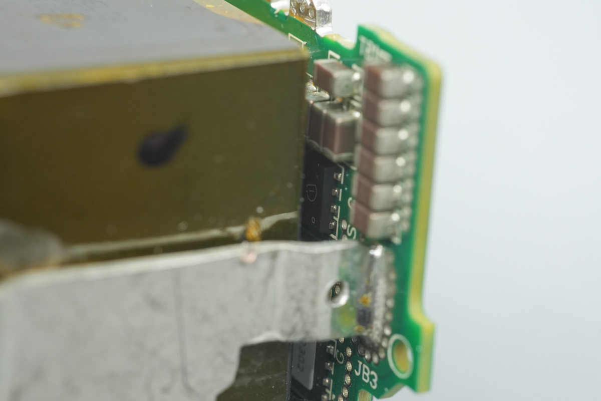
There are 3 synchronous rectifier MOSFETs of the same model on the inner side of the PCB.
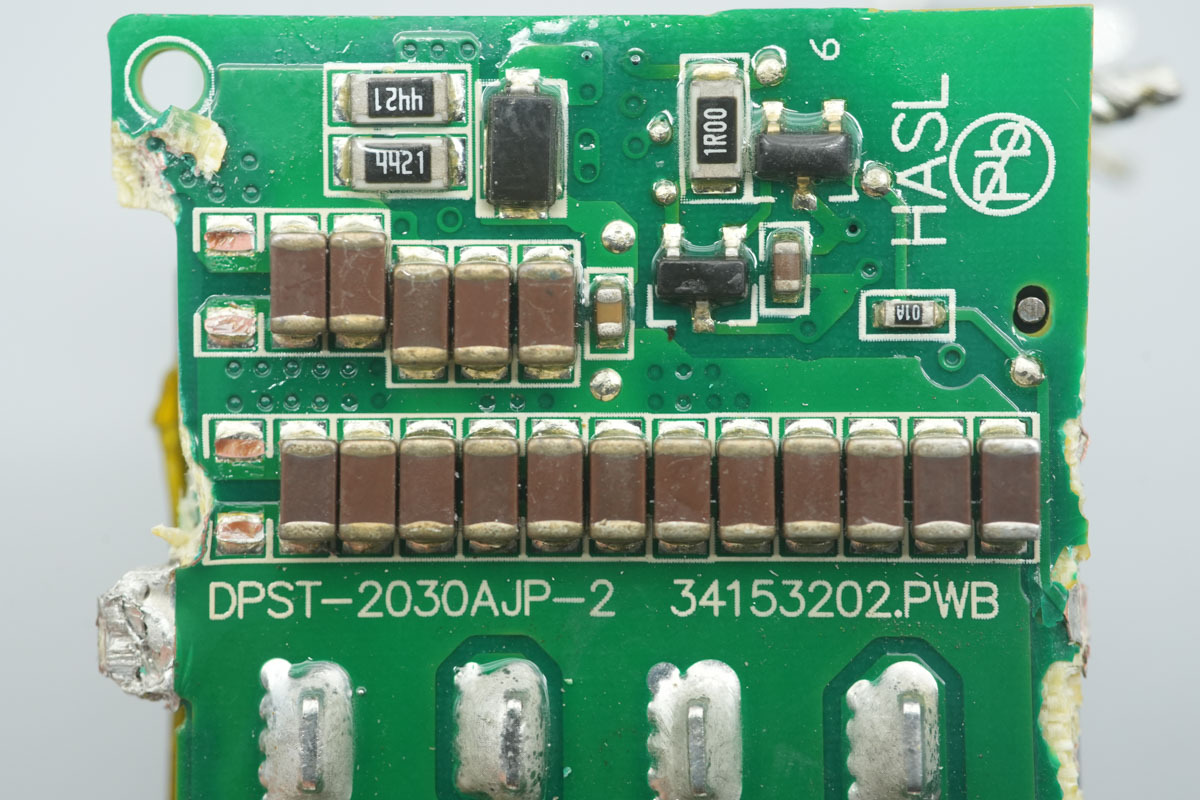
The MLCCs.
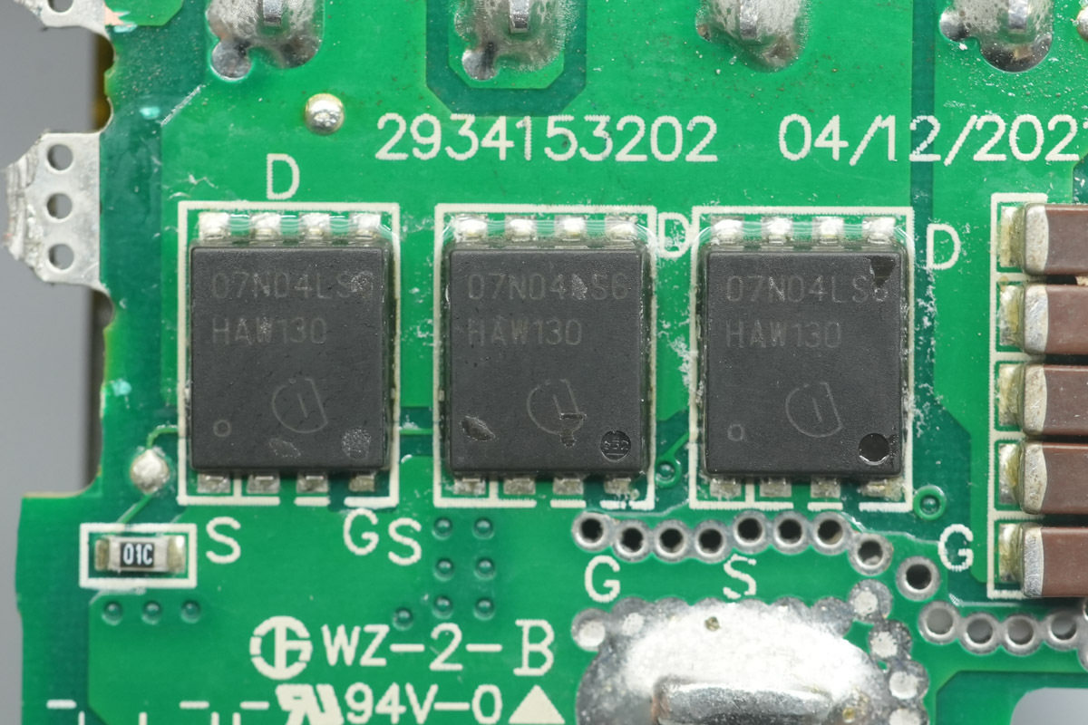
The other side is equipped with synchronous rectifier MOSFETs of the same model.
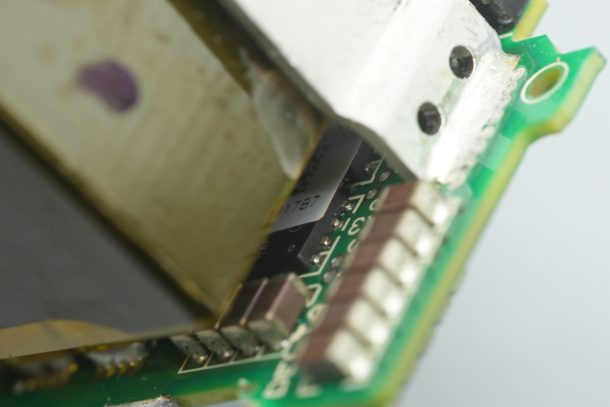
The inner side is equipped with synchronous rectifier MOSFETs of the same model.
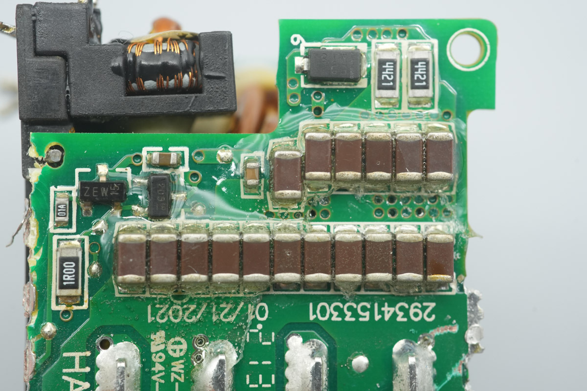
The MLCCs.
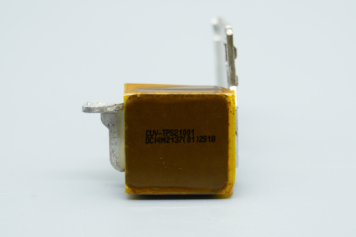
The output filtering inductor, with the magnetic core wrapped in insulating tape.
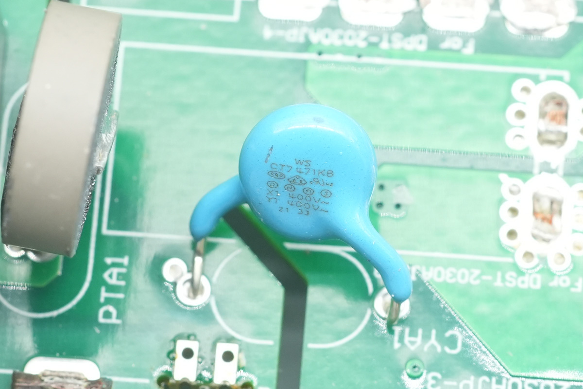
The blue Y-cap, model CT7 471KB.
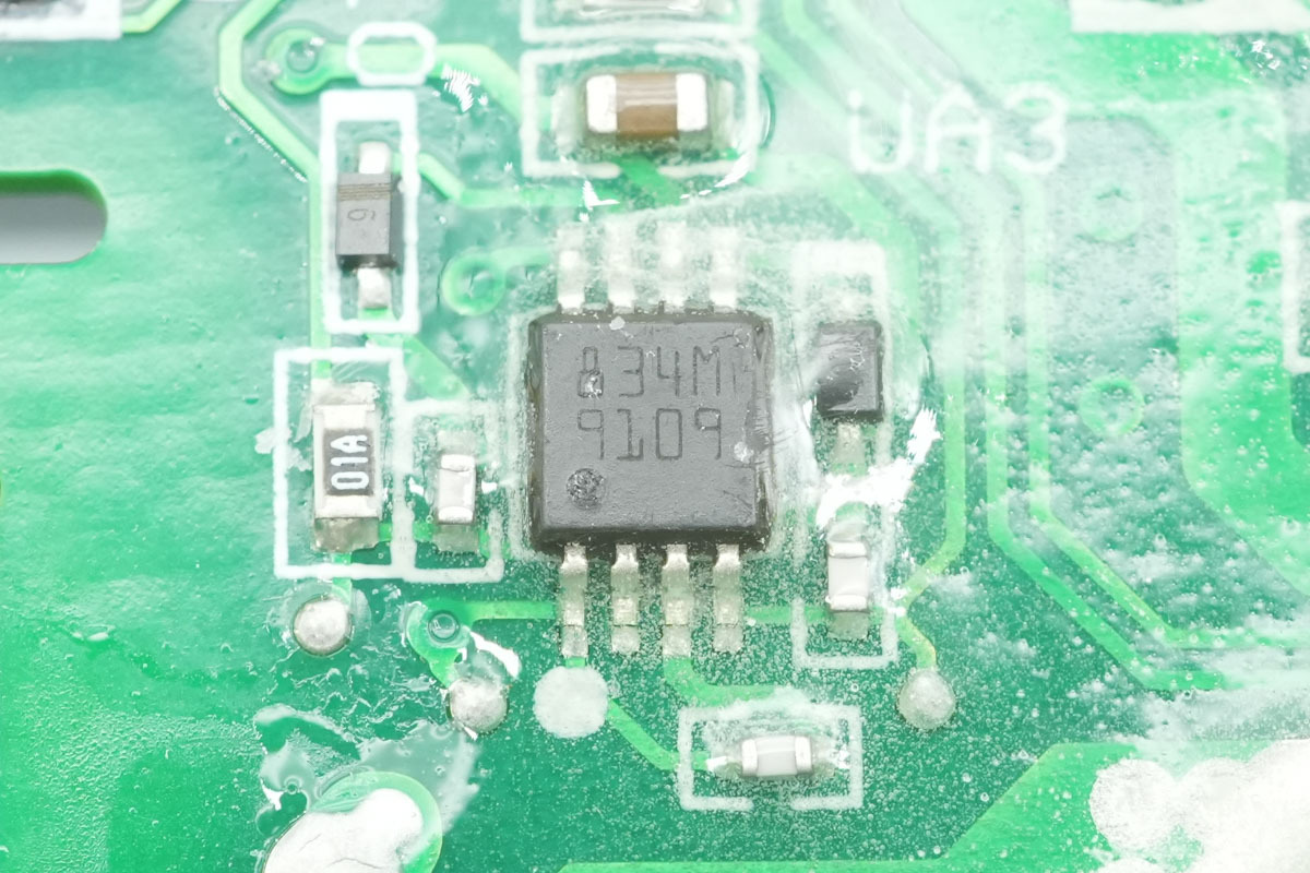
The synchronous rectifier MOSFET driver adopts the ST PM8834.
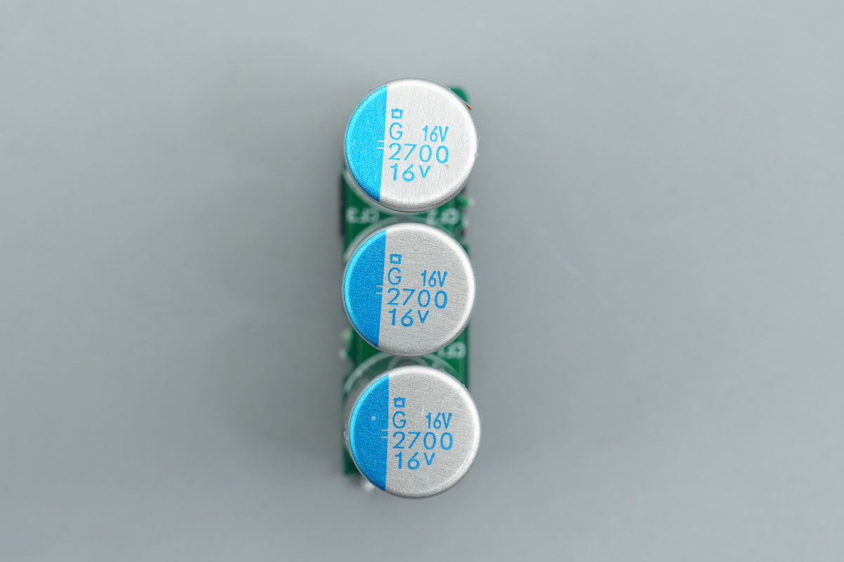
The filtering caps are from NCC, belonging to the PSG series conductive polymer aluminum solid electrolytic cap, spec 2700μF16V.
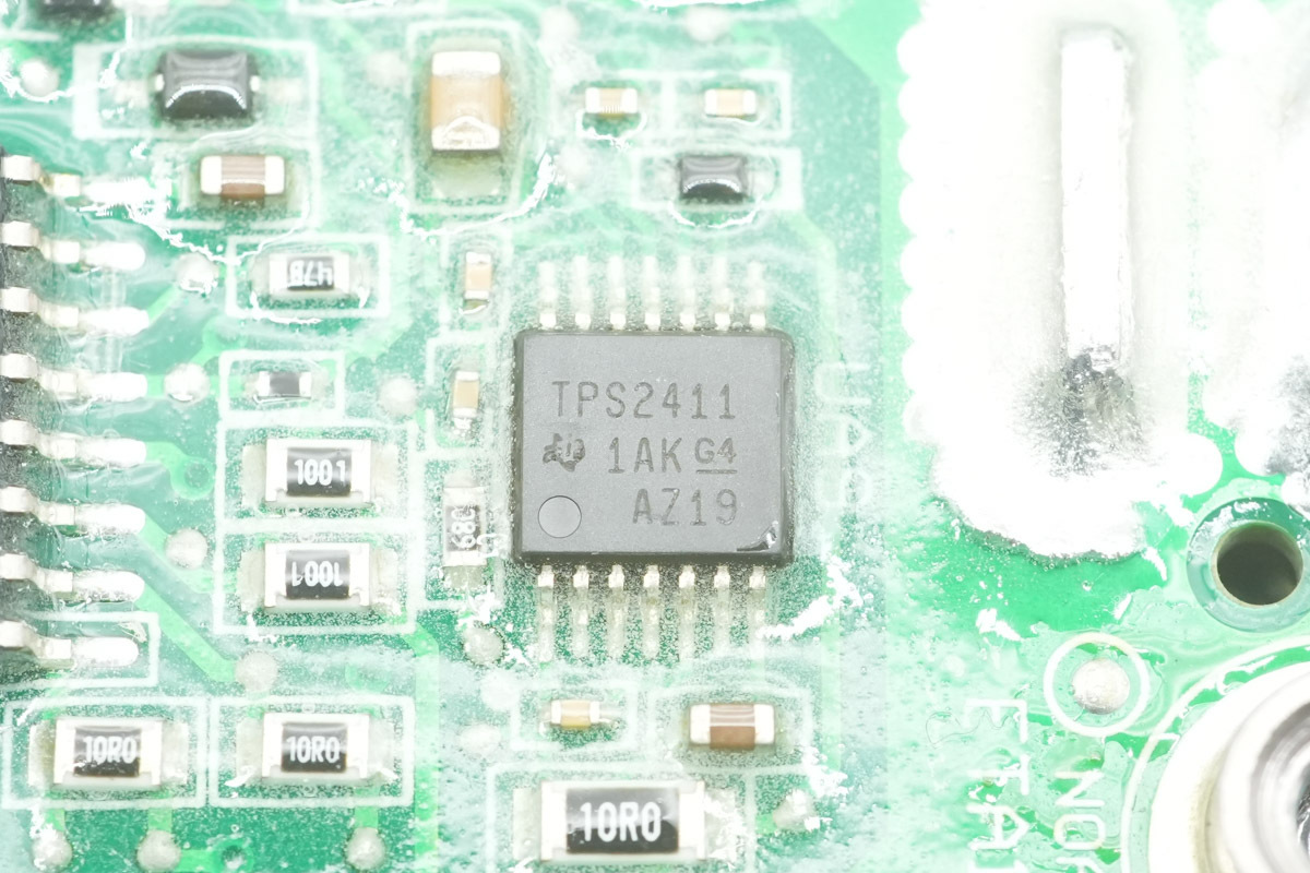
The ideal diode controller is from TI, model TPS2411, a fully-featured N+1 and ORing power rail controller supporting a bus voltage range of 0.8V to 16.5V, adopting a TSSOP14 package.
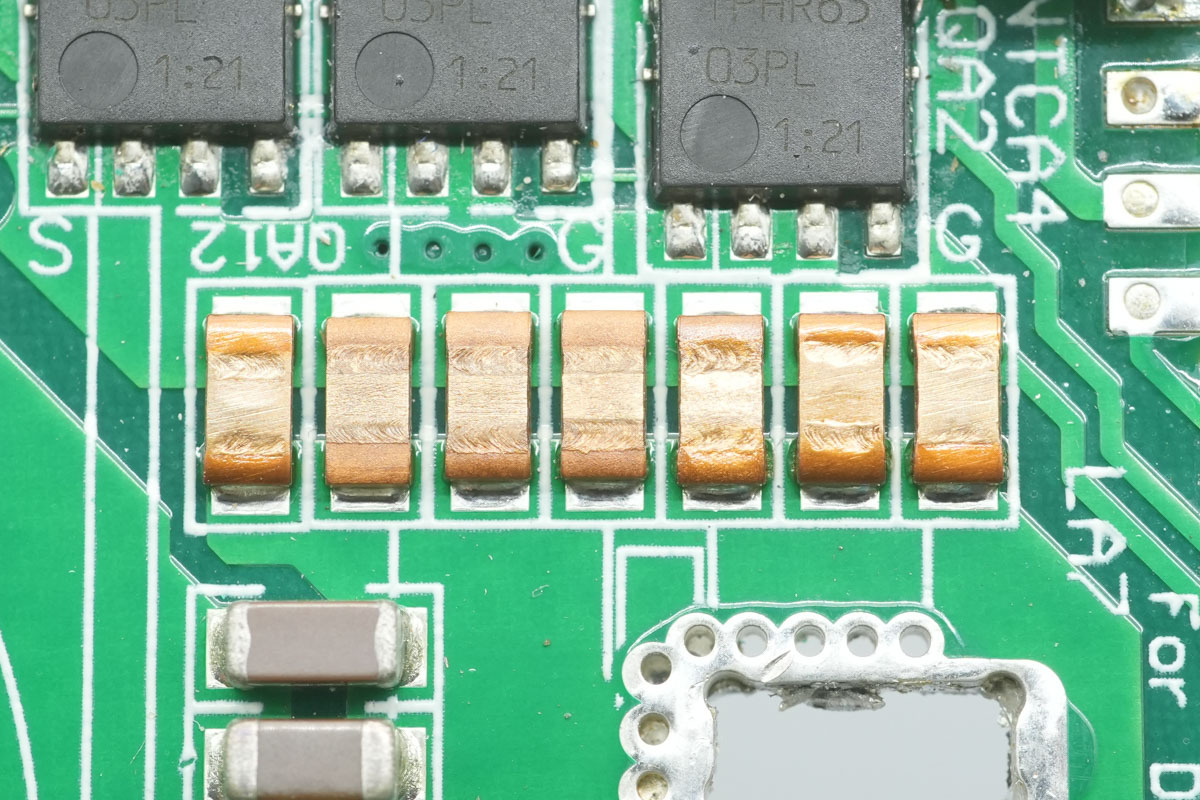
The SMD resistors, used for output current detection.
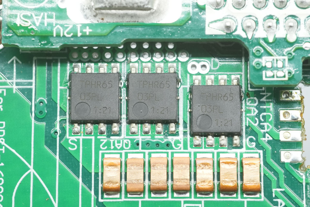
The output control MOSFETs are from TOSHIBA, model TPHR6503PL, NMOS, 30V and 0.41mΩ, adopting a SOP Advance package.
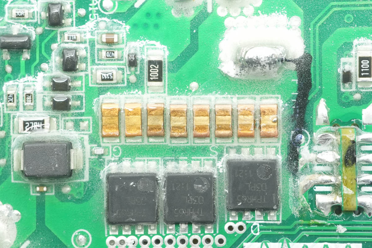
The back of the PCBA module is also equipped with SMD resistors for output current detection.
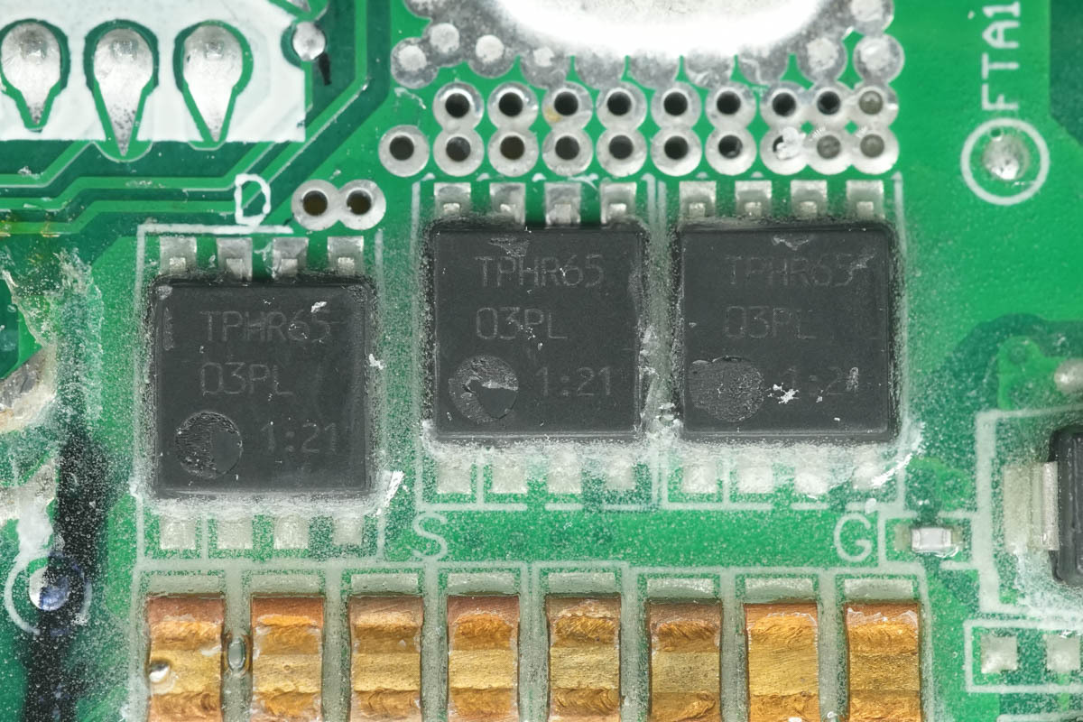
The output control MOSFETs on the back share the same model.
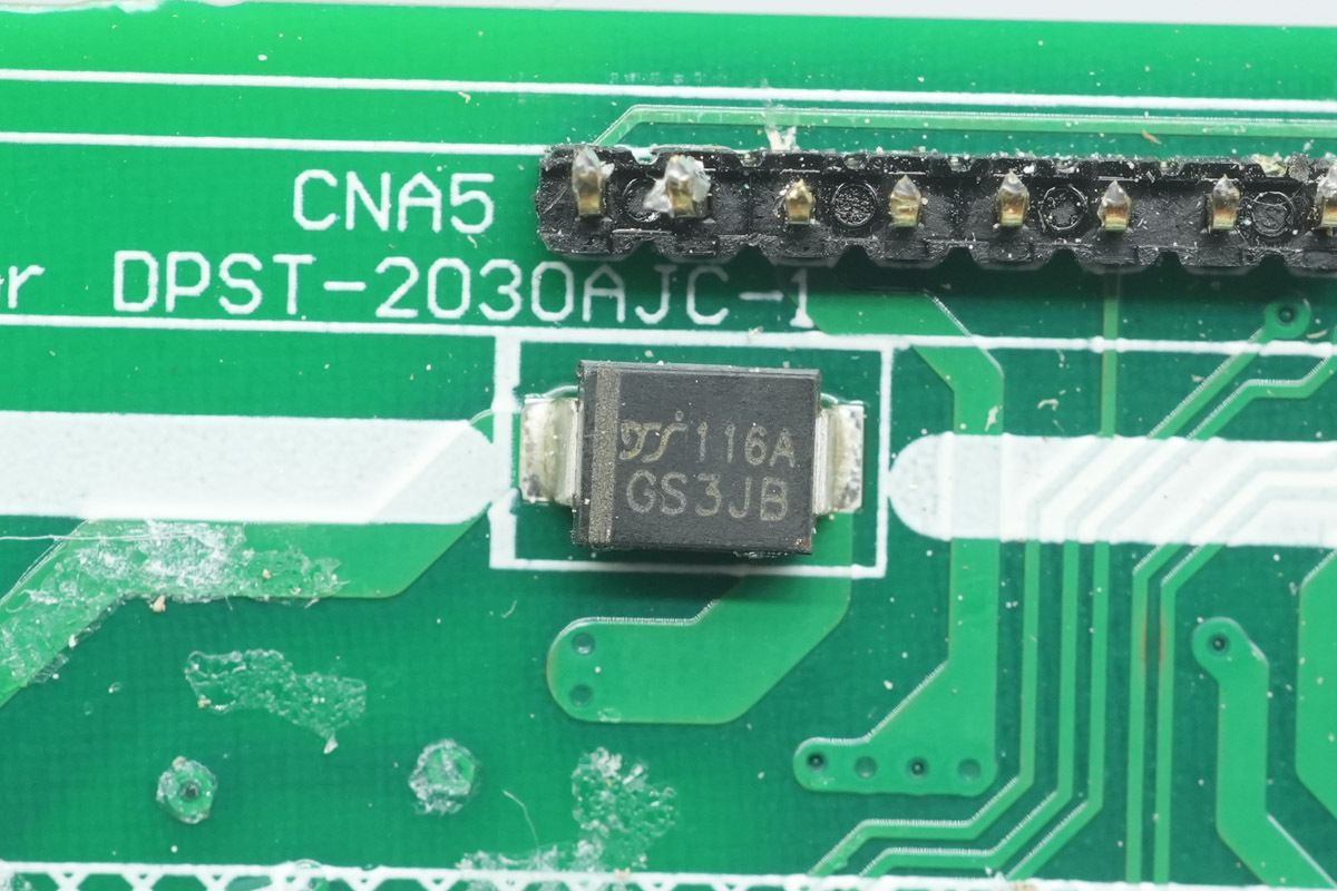
The diode is from YJ, model GS3JB, spec 600V 3A, adopting an SMB package.
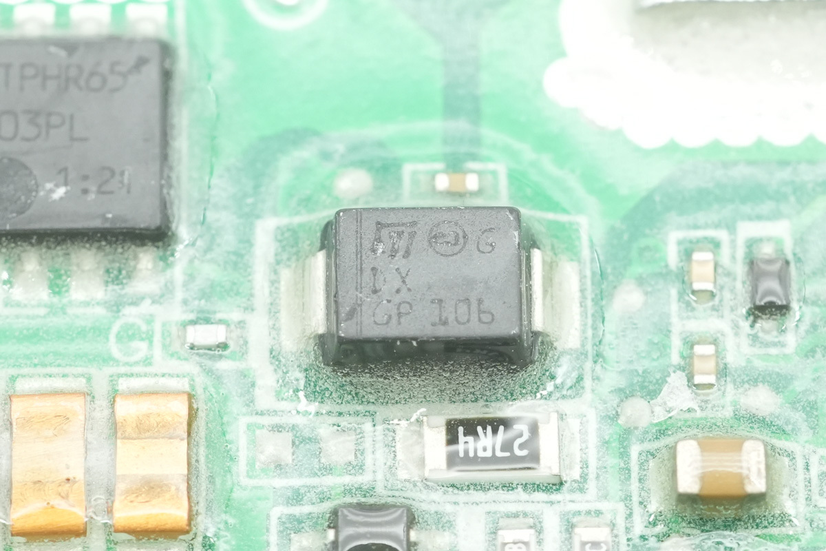
The TVS is from ST, marked DX, model SM6T15A, with a reverse standoff voltage of 15V, adopting an SMB package.
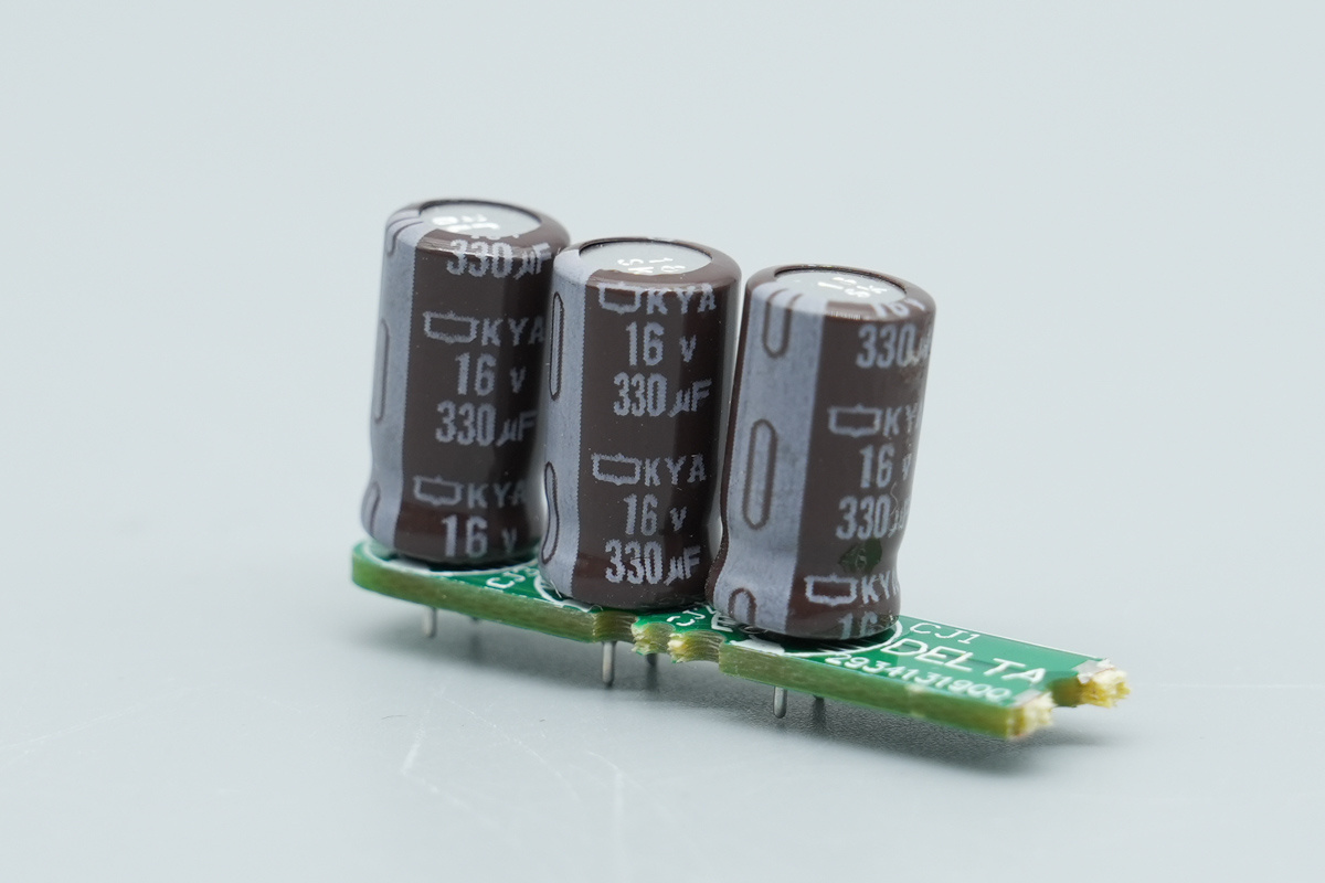
The output filtering cap is from NCC, spec 16V330μF.
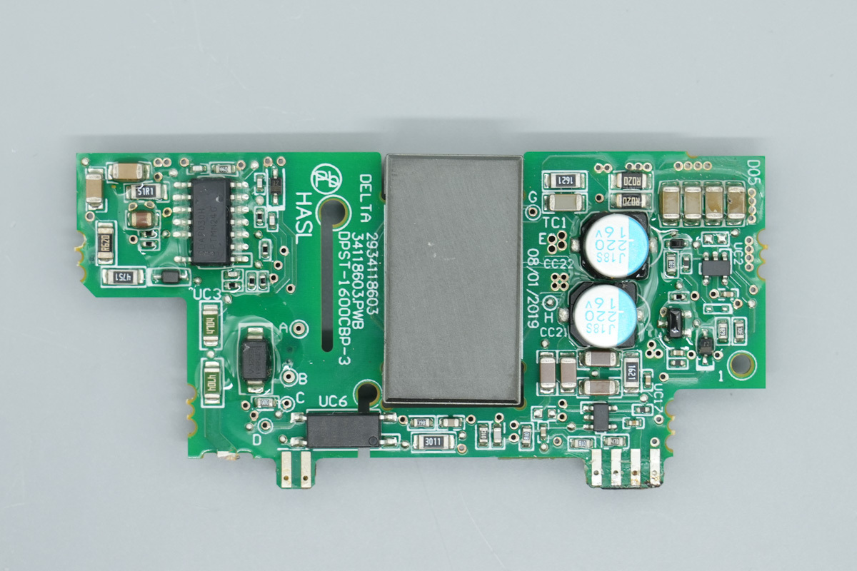
The auxiliary power PCB is equipped with the master control chip, optocoupler, and filtering caps.
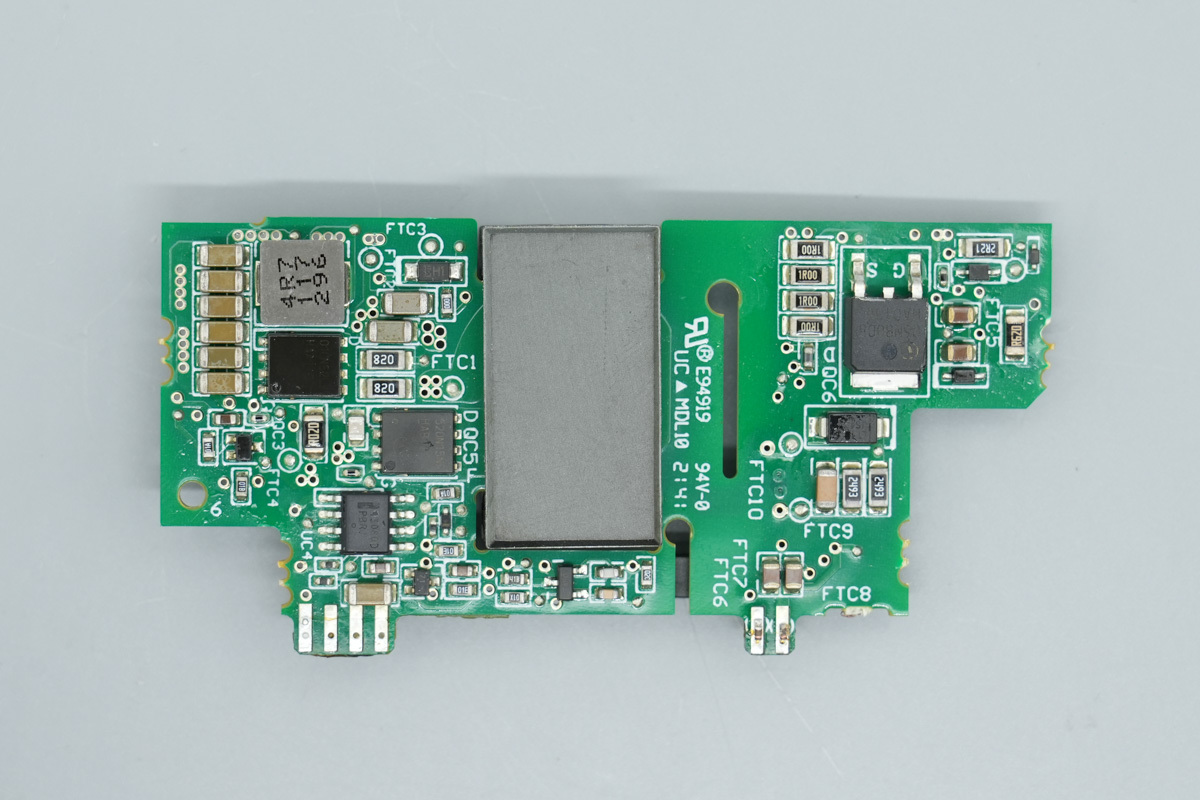
The other side is equipped with the synchronous rectifier controller, power supply control MOSFET, and primary MOSFET.
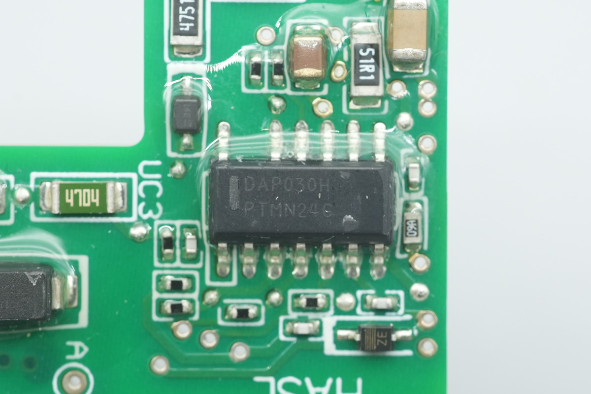
The master control chip is from Delta, model DAP030H, adopting a SOIC-14 package.
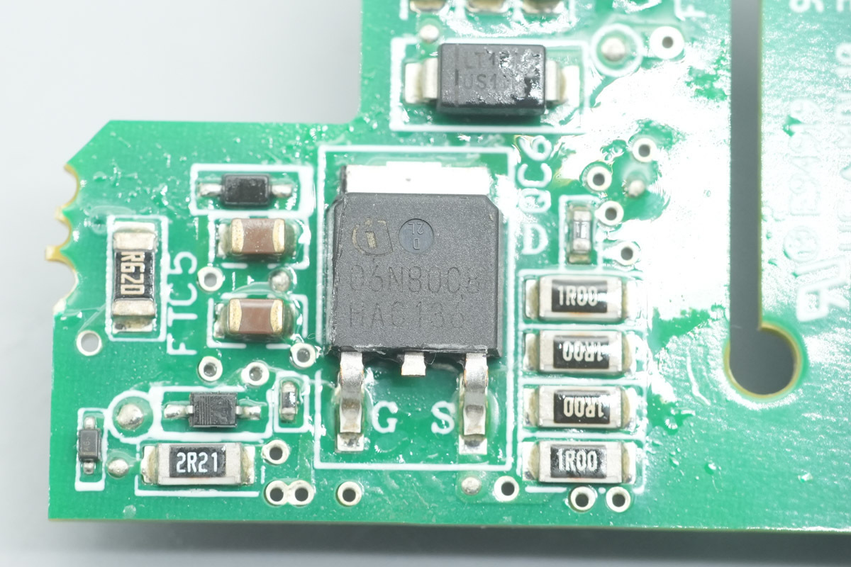
The MOSFET is from Infineon, model SPD06N80C3, NMOS, 800V and 900mΩ, adopting a TO252-3 package.
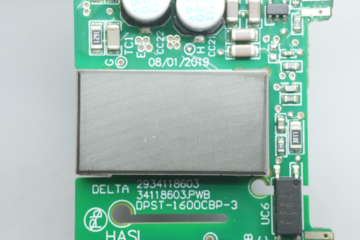
The planar transformer magnetic core.
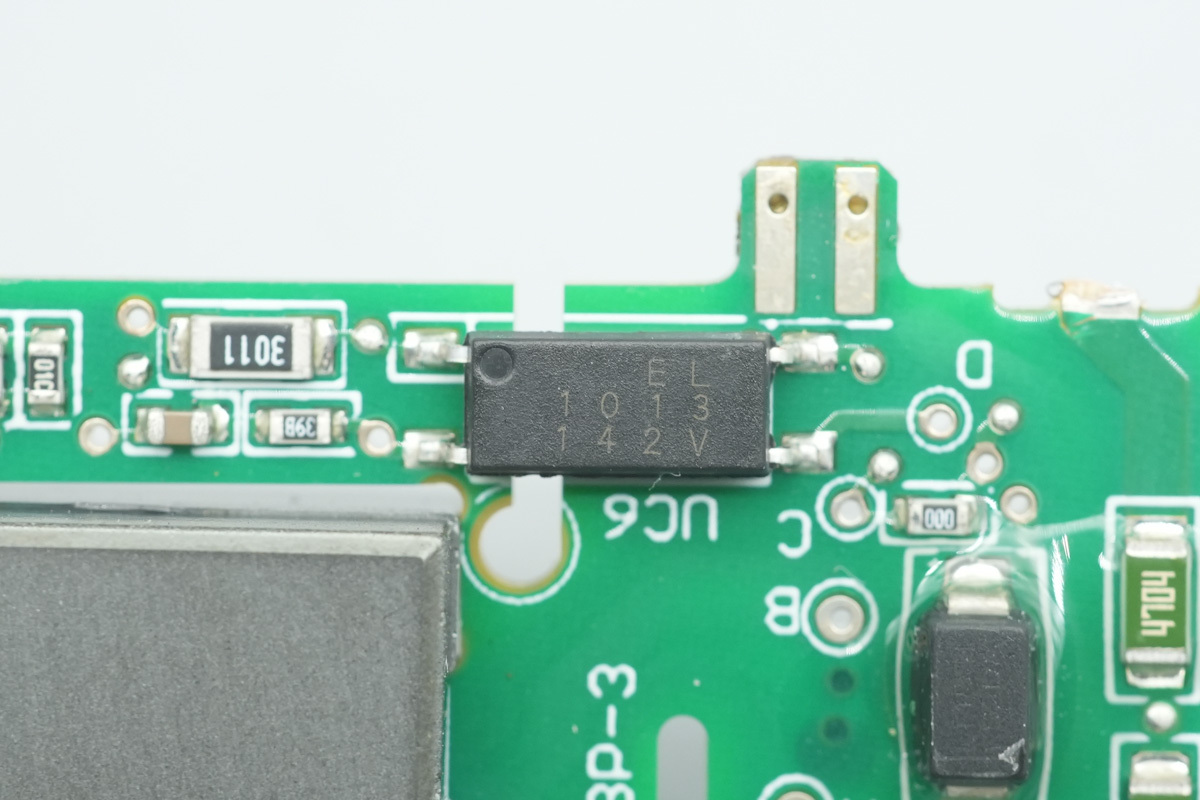
The Everlight EL1013 optocoupler is used for output voltage feedback.
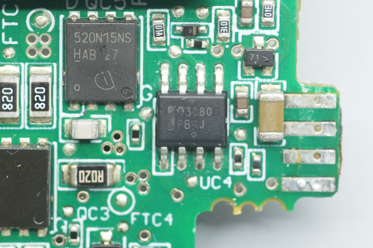
The synchronous rectifier controller is from onsemi, model NCP43080, supporting flyback, forward, and LLC applications. It features an automatic light-load mode, adaptive gate drive clamping, and supports a 1-MHz switching frequency, adopting a SOIC-8 package.
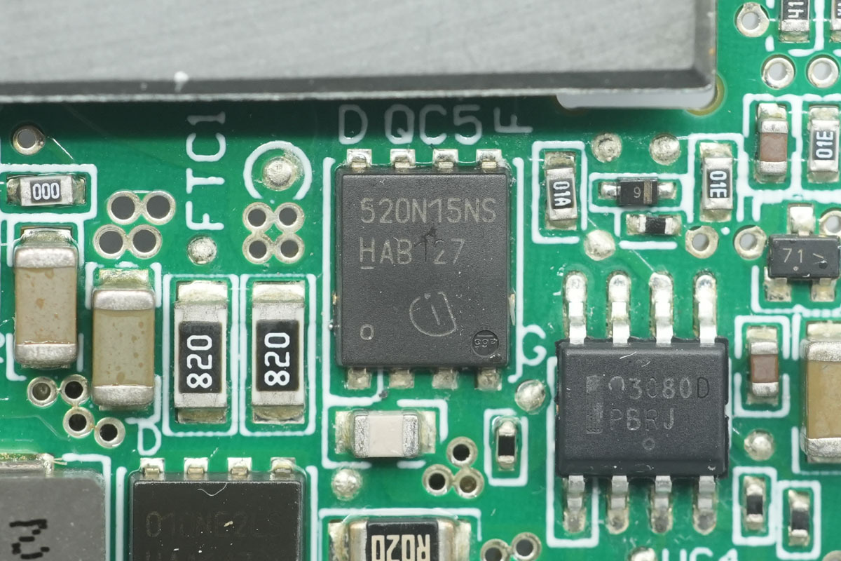
The synchronous rectifier MOSFET is from Infineon, model BSC520N15NS, NMOS, 150V and 52mΩ, adopting a TDSON-8 package.
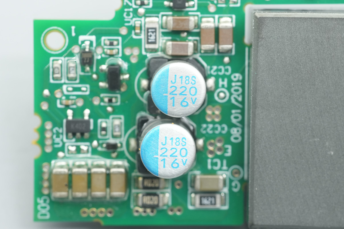
The filtering caps are from NCC, belonging to the PXJ series conductive polymer aluminum solid electrolytic cap, spec 220μF16V.
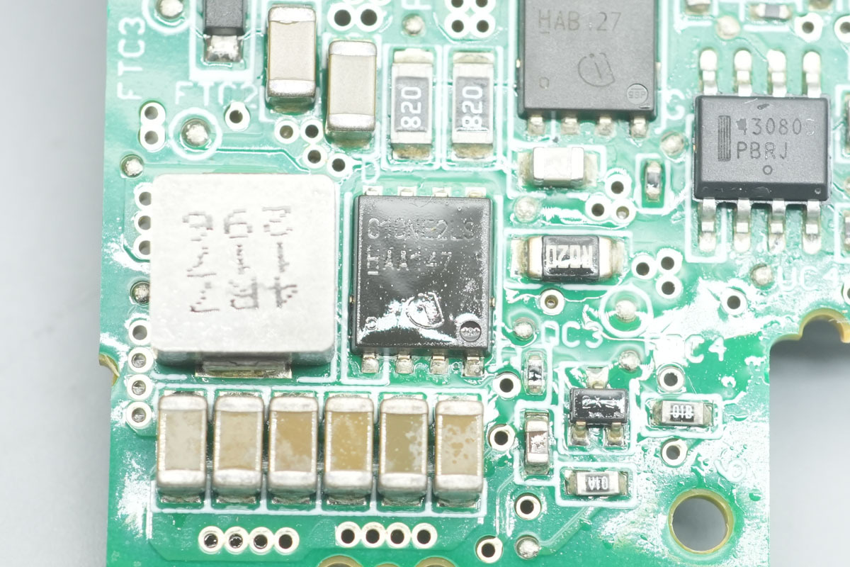
The power supply control MOSFET is from Infineon, model BSC018NE2LS, NMOS, 25V and 1.8mΩ, adopting a TDSON-8 package.
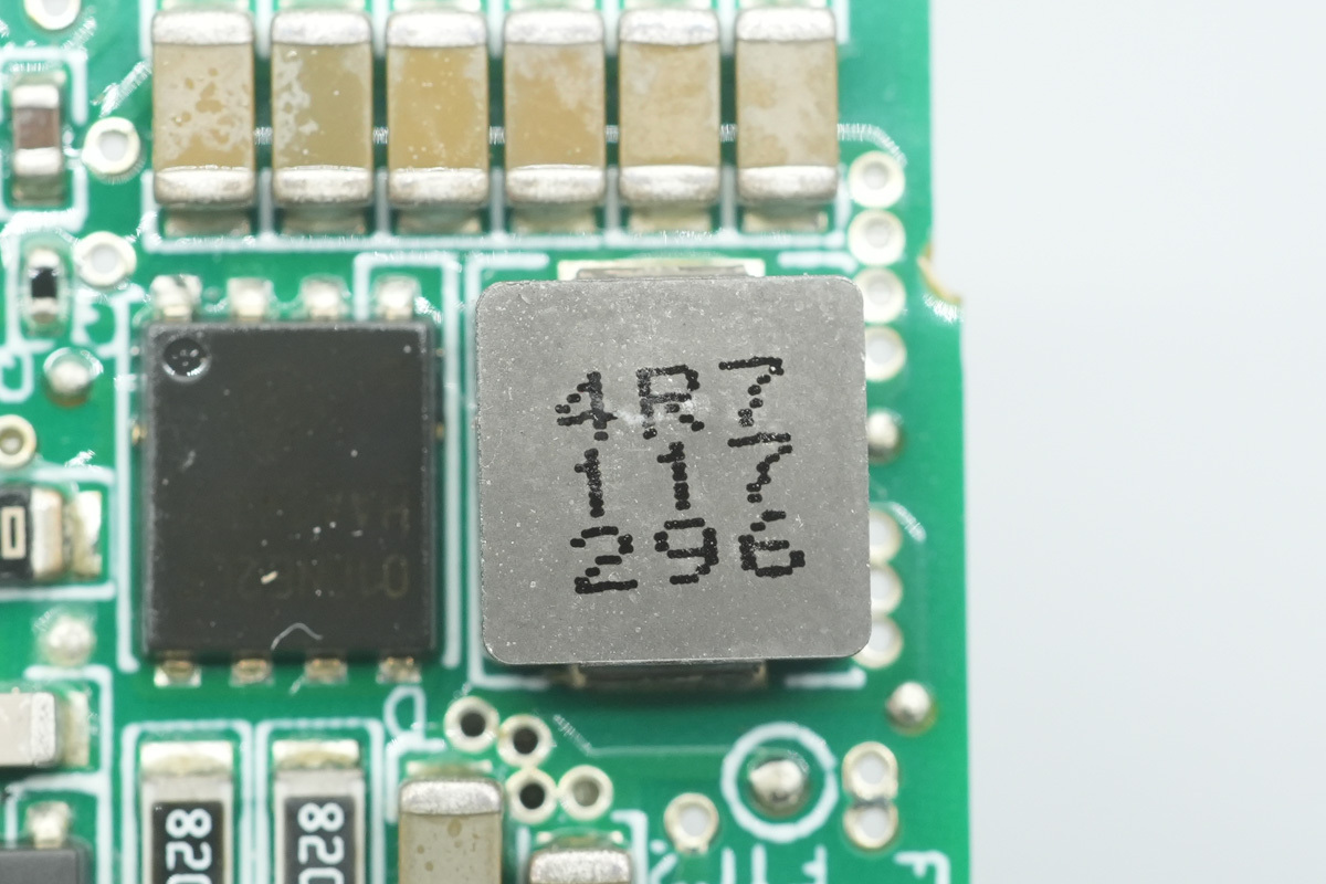
The 4.7μH filtering inductor.
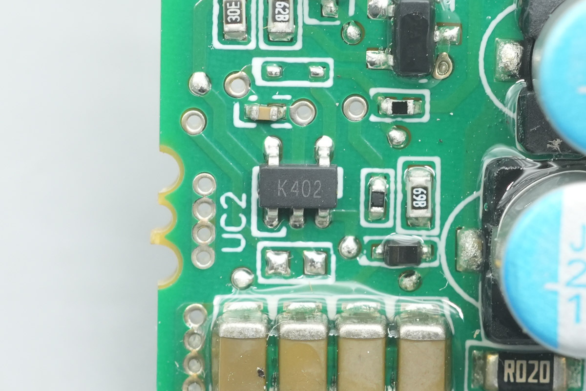
The operational amplifier adopts the ST TS321AILT.
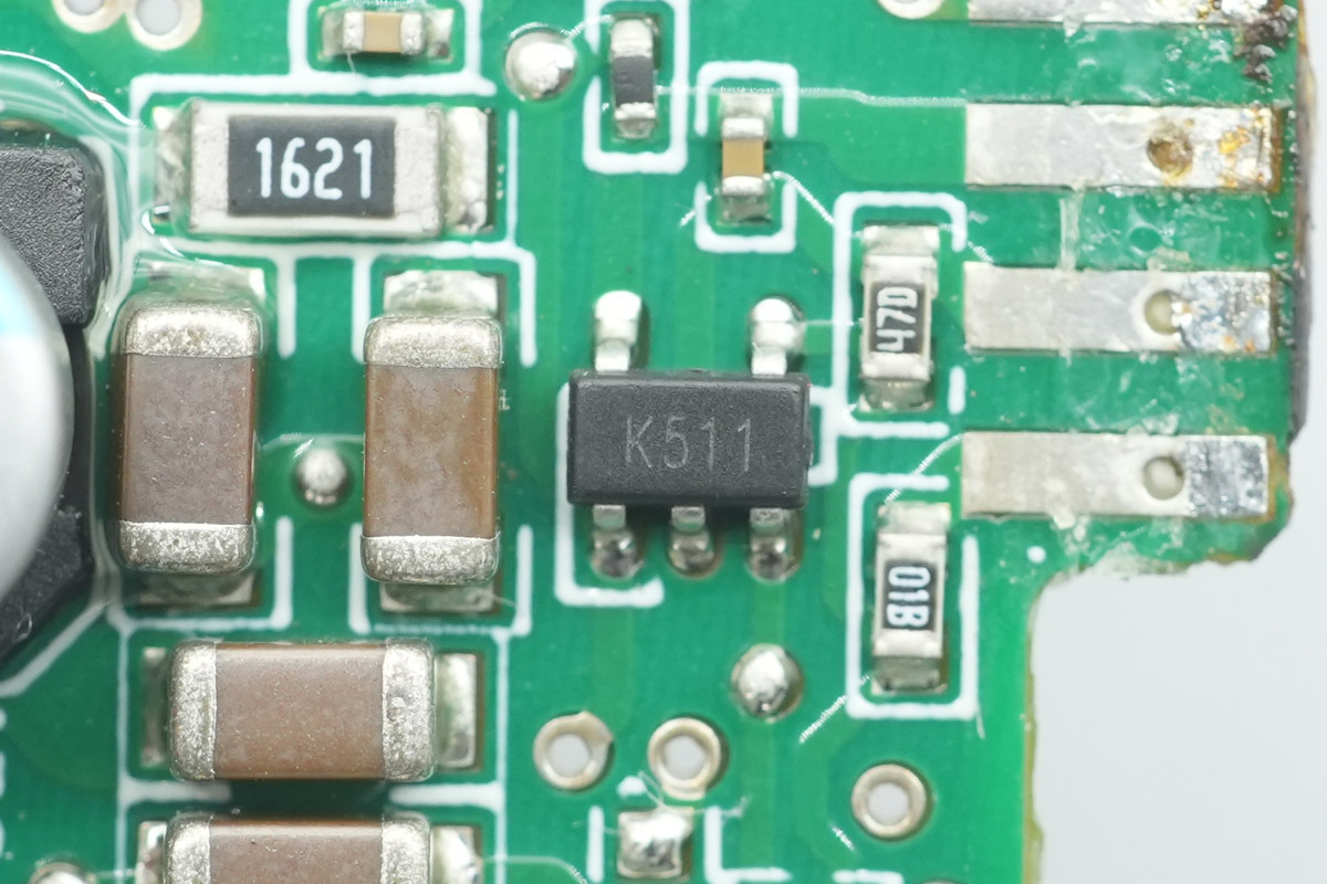
The voltage comparator is from ST, marked K511, model TS391ILT, a low-power single voltage comparator adopting a SOT23-5 package.
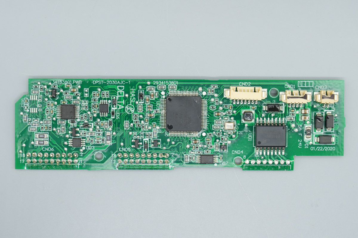
The inner side of the control PCB is equipped with a real-time microcontroller, memory, operational amplifier, voltage comparator, and digital isolation chips.
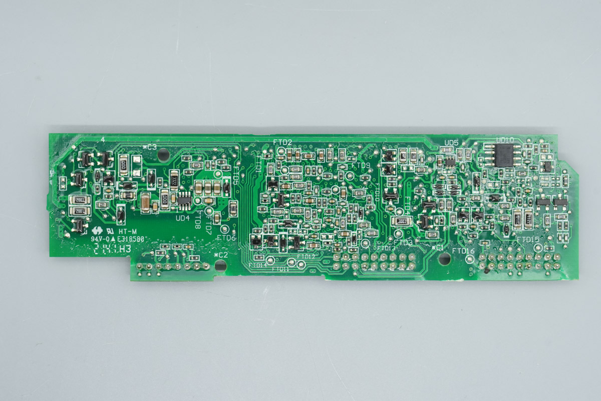
The outer side of the control PCB is equipped with a synchronous step-down chip, current sense chip, and operational amplifier.
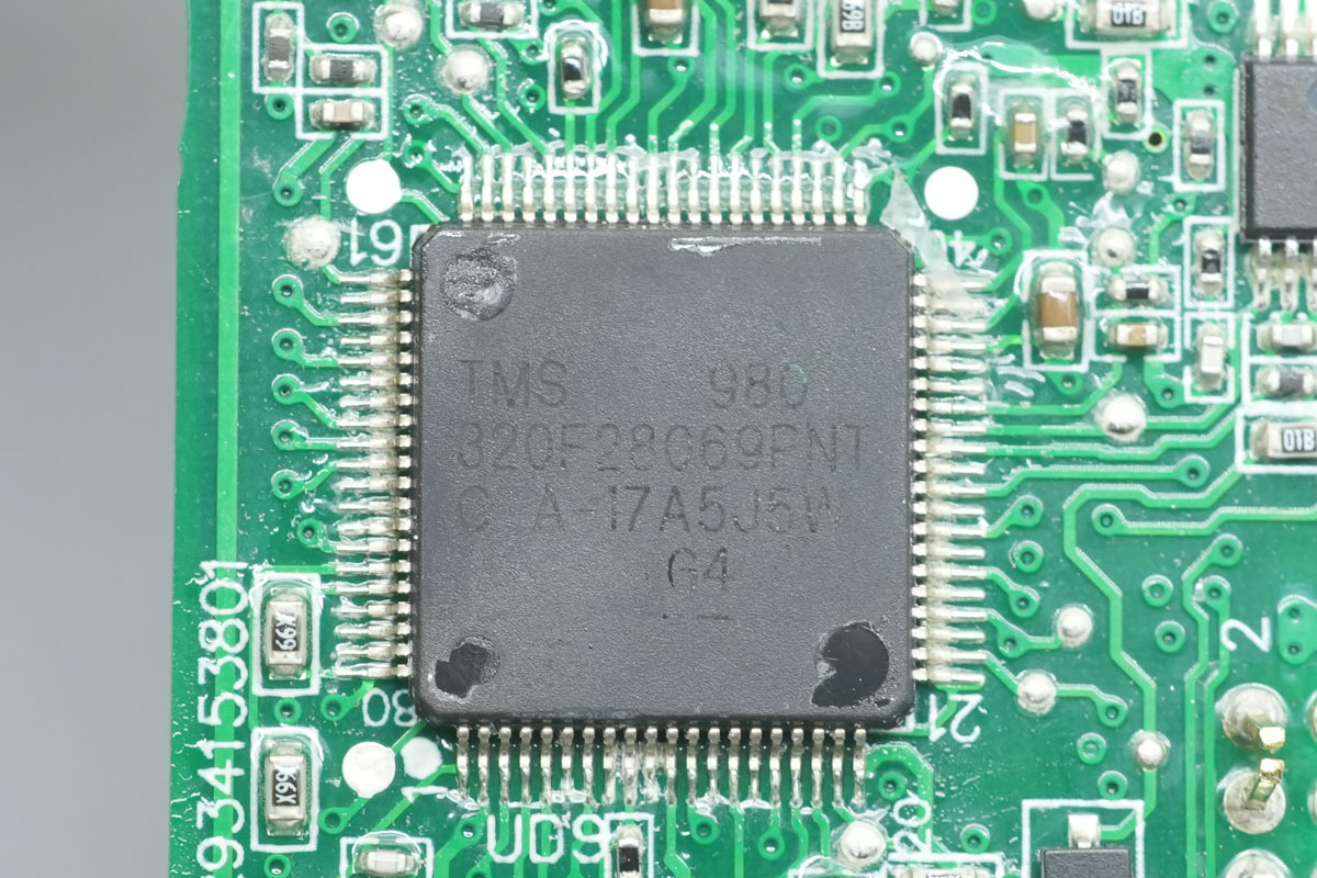
The real-time microcontroller is from TI, model TMS320F28069PNT, a C2000 series 32-bit microcontroller integrating a 32-bit CPU with a 90MHz main frequency, FPU, and CLA. The chip integrates 128KB Flash and 50KB SARAM, adopting an LQFP80 package.
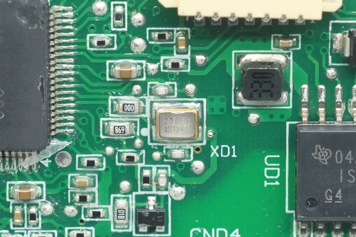
The 20.00MHz clock crystal oscillator.
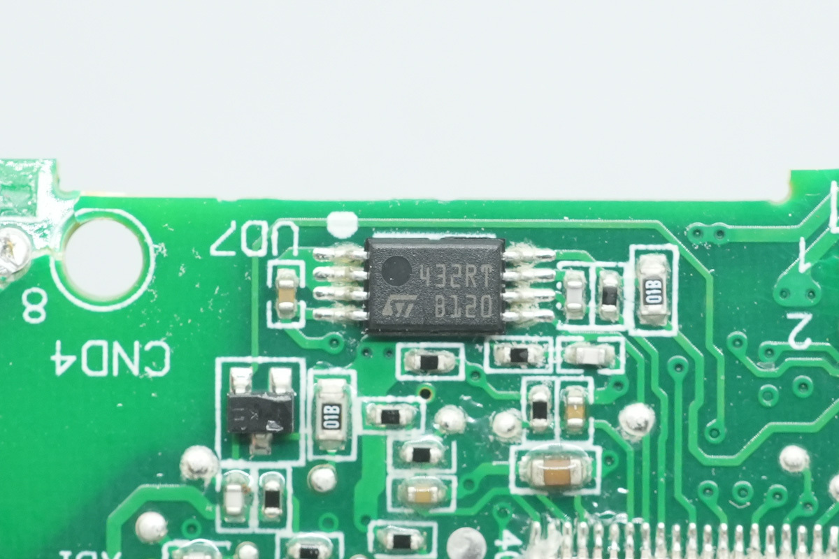
The memory is from ST, marked 432RT, model M24C32-RDW6TP, with a capacity of 4KB, supporting an operating voltage of 1.7V to 5.5V, adopting a TSSOP8 package.
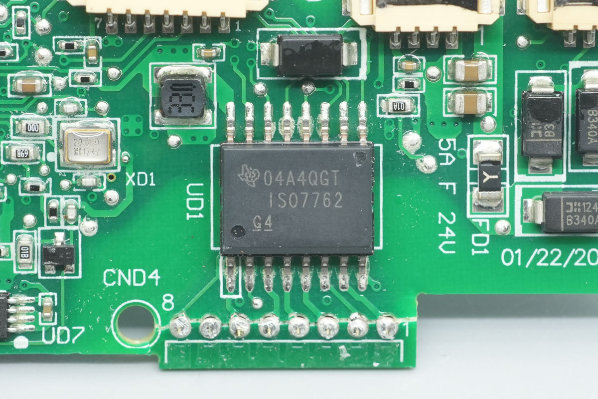
The digital isolation chip is from TI, model ISO7762, a high-performance 6-channel digital isolator featuring 4 forward channels and 2 reverse channels, supporting a 100 Mbps transmission rate, with an isolation rating of up to 5000VRMS and an operating voltage range of 2.25V to 5.5V, adopting a SOIC16 package.
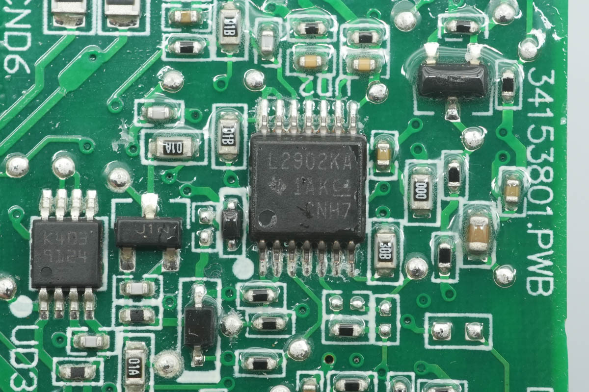
The operational amplifier is from TI, model LM2902KAV, a quad general-purpose operational amplifier featuring improved ESD performance, adopting a TSSOP14 package.
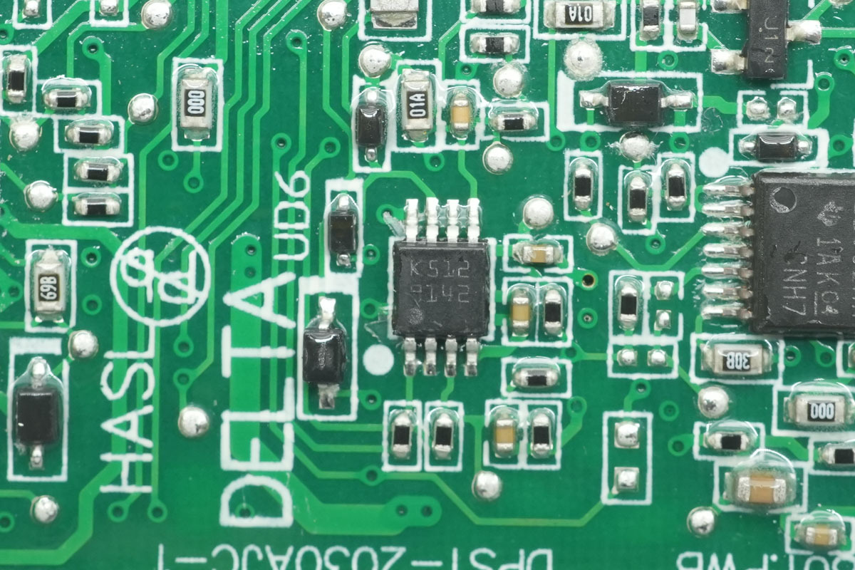
The voltage comparator adopts the ST LM293ST.
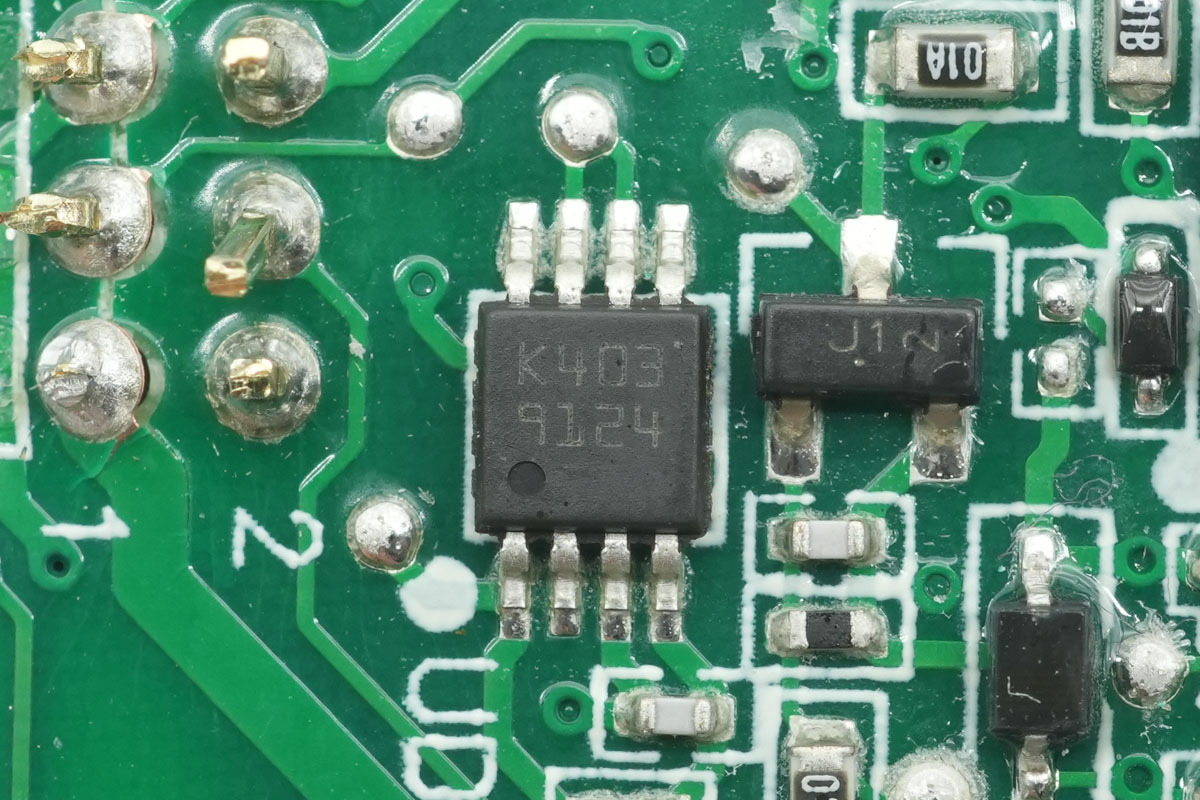
The operational amplifier is from ST, marked K403, model LM2904ST, a low-power dual operational amplifier adopting a MiniSO8 package.
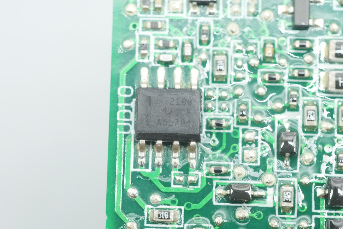
The operational amplifier is from TI, model OPA2188, a low-noise, rail-to-rail output, 36V zero-drift operational amplifier adopting a SOIC8 package.
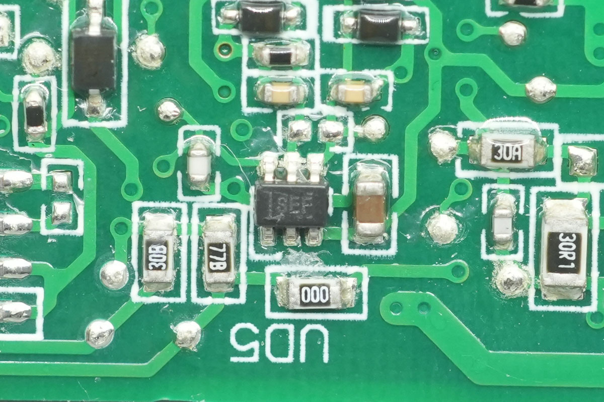
The current sense chip is from TI, marked SEF, model INA213, a 26V-rated bidirectional high-precision current sensing amplifier adopting an SC70 package.
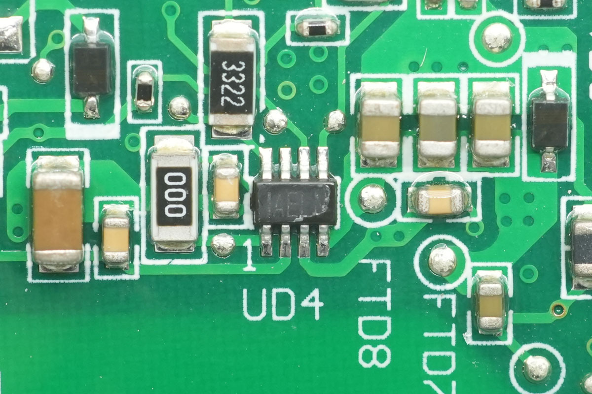
The synchronous step-down chip adopts the MPS MP2314.
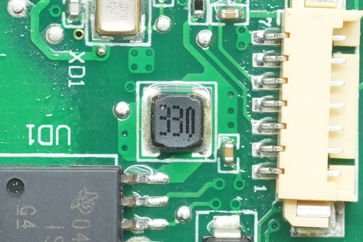
The 33μH step-down choke.
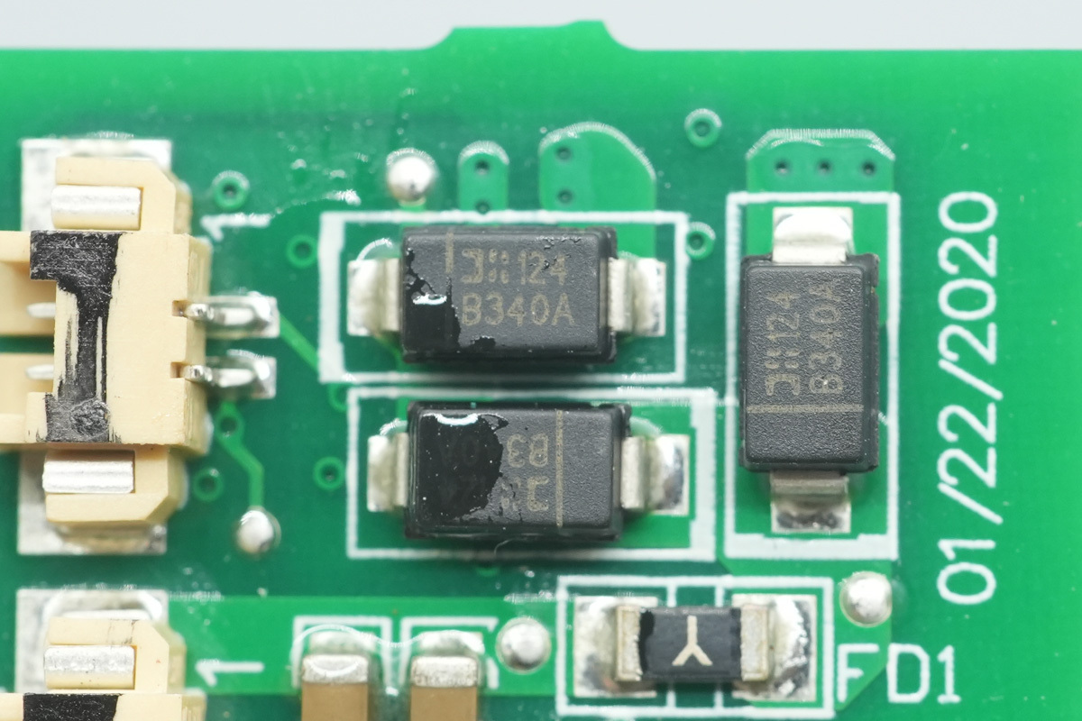
The diode is from DIODES, model B340A, a Schottky diode with a spec of 40V 3A, adopting an SMA package.
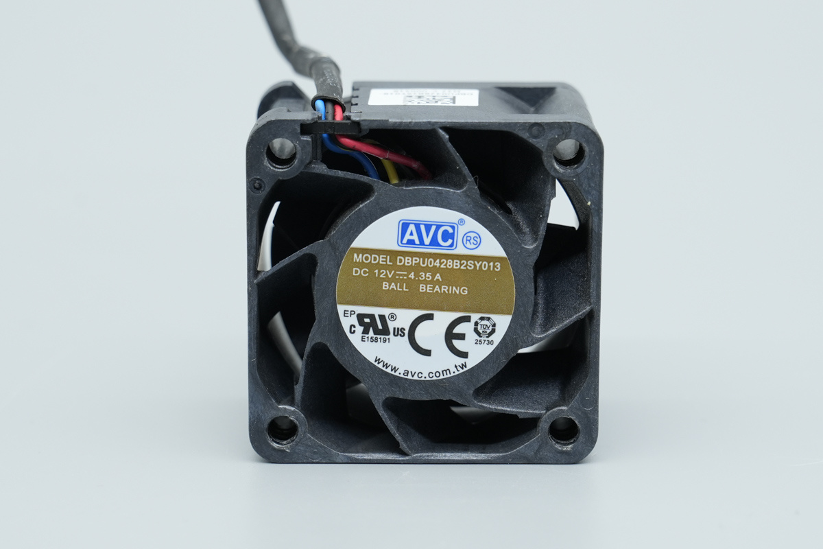
The cooling fan is from AVC, model DBPU0428B2SY013, spec 12V⎓4.35A, made in China, and equipped with stationary guide vanes.
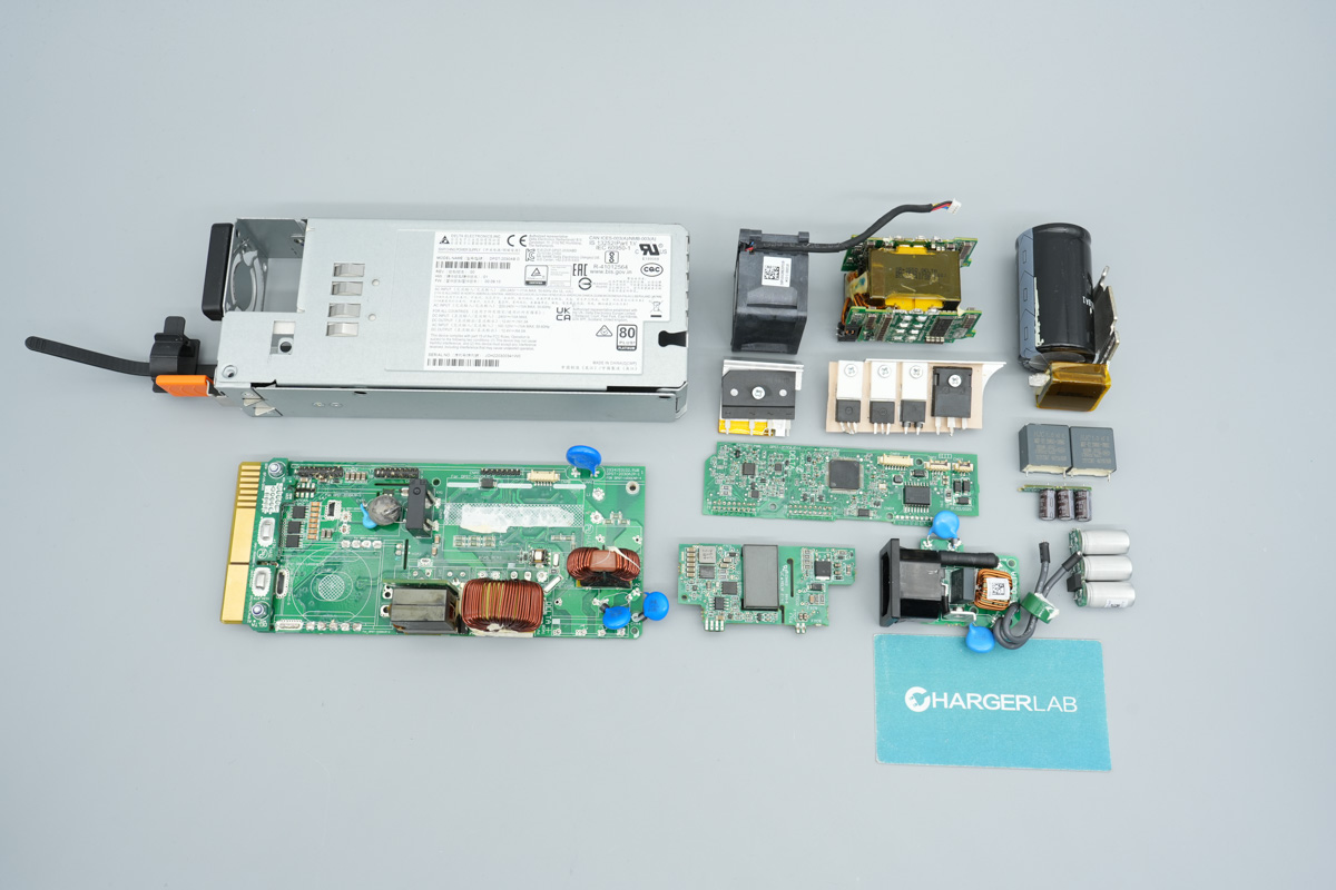
Well, those are all components of the Delta 2030W SiC Server Power Supply DPST-2030AB D.
Summary of ChargerLAB
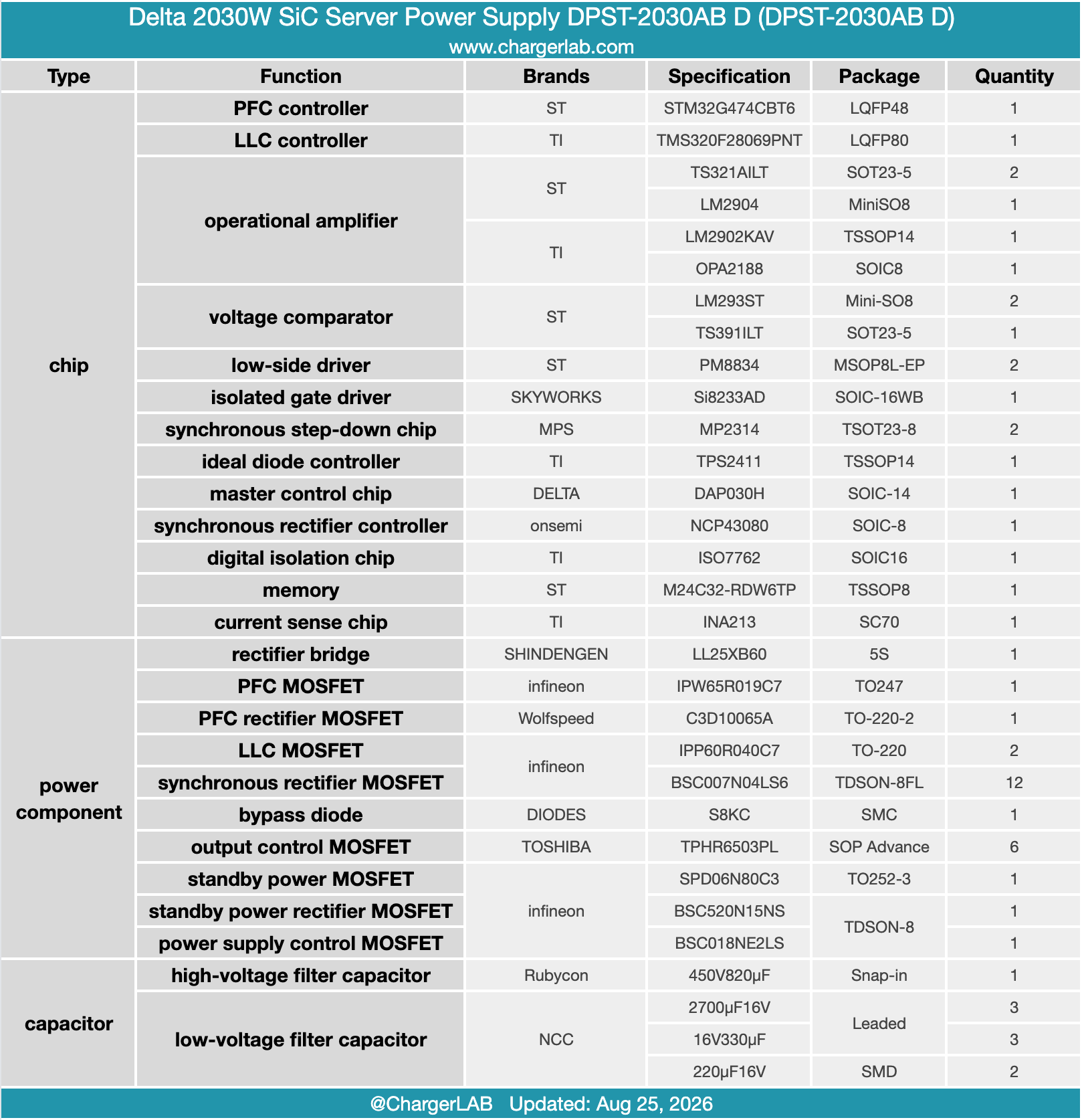
Delta 2030W SiC server power supply (Model: DPST-2030AB D) accommodates universal 100–120V / 200–240V AC inputs alongside 240V DC inputs, delivering a steady 12.4V output at 161.3A. The exterior houses the cooling fan and AC inlet, while the internal end features gold-finger connectors. The cooling layout adopts an internal-to-external airflow design, pulling air from the system side and exhausting it out the rear.
The teardown reveals an advanced PFC + LLC + synchronous rectification topology. The PFC stage is governed by an ST STM32G474CBT6 controller, pairing an ST PM8834 driver with an Infineon IPW65R019C7 power MOSFET and a Wolfspeed C3D10065A SiC Schottky diode.
The LLC resonant stage relies on a TI TMS320F28069PNT real-time controller, a SKYWORKS Si8233AD isolated gate driver, Infineon IPP60R040C7 primary MOSFETs, and ST PM8834 drivers coupled with Infineon BSC007N04LS6 MOSFETs for synchronous rectification. Signal isolation is managed by a TI ISO7762 digital isolator. Premium Japanese electrolytic caps are used extensively for robust filtering, reflecting top-tier industrial build quality.


